1. Cutting of circuit board
1.1 Preparation for processing work
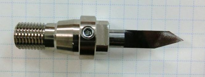
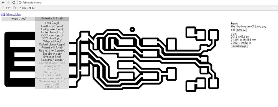
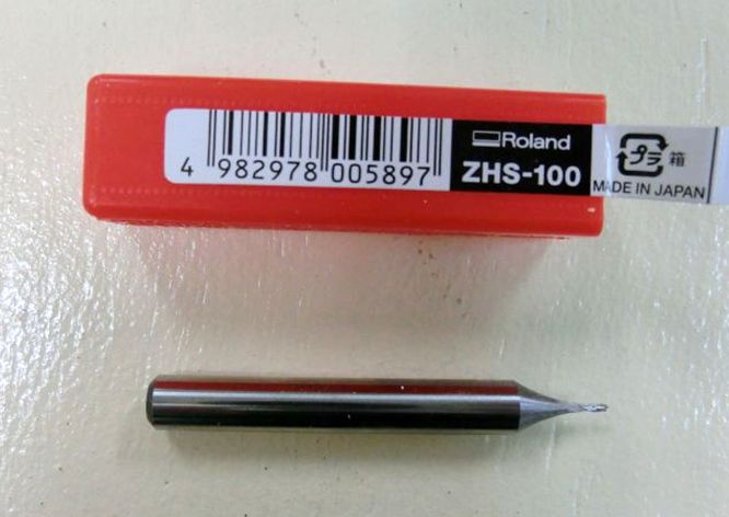
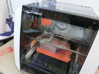
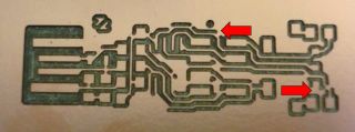
I processed the board using Roland's SRM-20. I got the 1/64 and 1/32 end mills from the gru, but I could not use it. Because there is no collet that attaches a thin end mill. Therefore, I decided to use a V-cut end mill for cutting the pattern. I used a 1 mm end mill to cut the pattern.
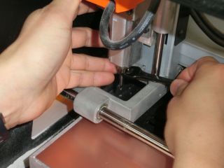
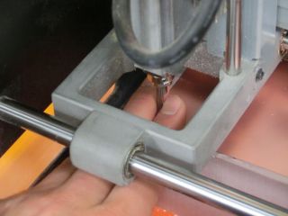
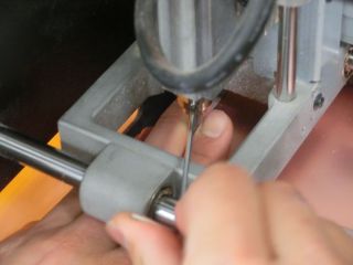
I was taught from Guru how to fit the end mill to the cutting surface while pinching end finger.

 1.2 Cutting of pattern
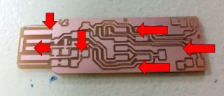
I referred to
last year's class archive and used processed images of
FabTiny*ISP.
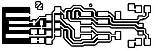
*Quote Sander van Vliet(2016)
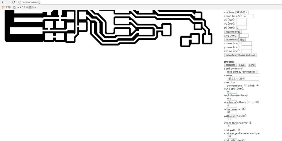
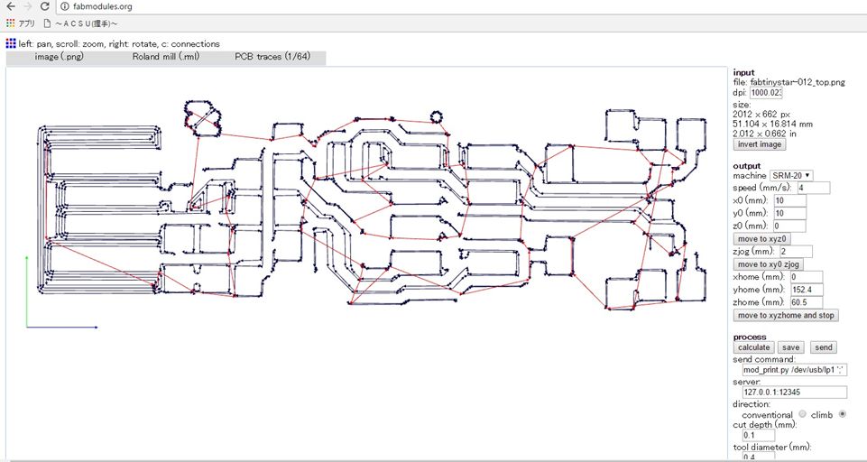
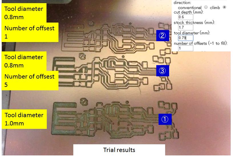
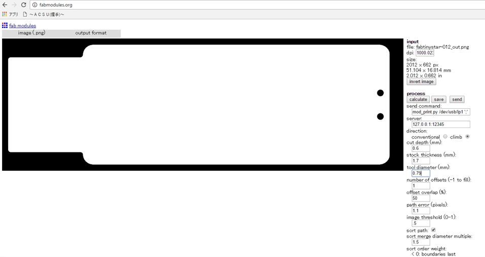
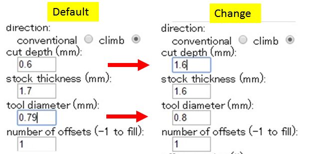
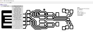
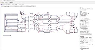
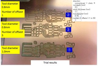
An image file of png format was read by the Fab system. The model setting was set to SRM - 20. The diameter of the end mill was adjusted, and the cutting simulation was confirmed. When the diameter of the end mill was 1 mm, the pattern was broken. Therefore, when it was set to 0.8 mm, it was confirmed that it can be successfully processed.
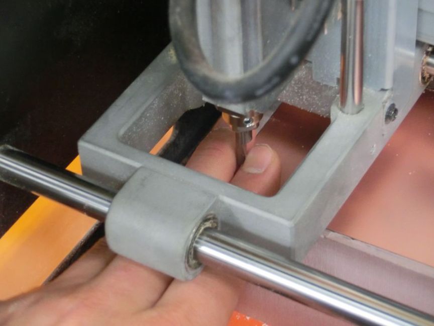
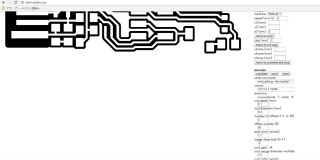
The cutting data file was saved and read with SRM - 20 control software. After setting the origin of XY, the height of the end mill was adjusted and the origin of Z was set.
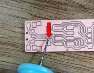
At the first time, when the diameter of the end mill was 1 mm, there was a pattern that could not be cut off
In the second time, the diameter of the end mill was set to 0.8 mm, but since it was repeated once, it could not be cut off. After repeating 5 times at the third time, it was completed.
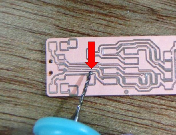
 1.3 Cutting of circuit board
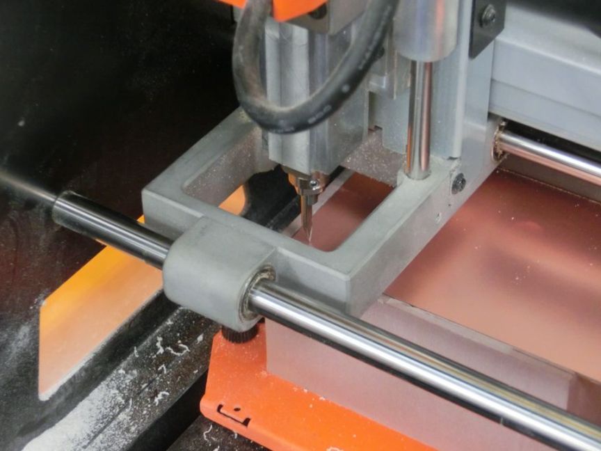
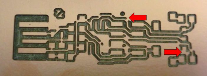
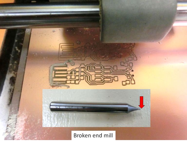
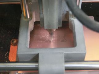
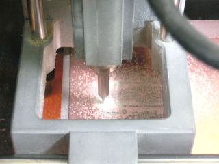
Next, I created data to cut the outer circumference of the circuit board. Like the pattern, reading cut miller was created and saved. It loaded into the control software of SRM - 20 and processed.
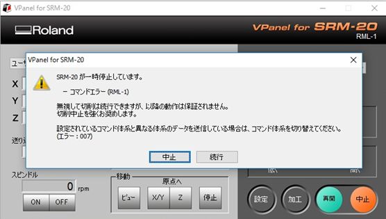
Processing was stopped because abnormal noise occurred immediately after processing. The end mill broke. As a result of confirming, it turned out that setting of depth of cutting was wrong. Because the default 0.6 mm was set to 1.6 mm, the end mill was overloaded and it broke.
I exchanged the end mill, checked the settings and processed it. I could cut the circuit board.


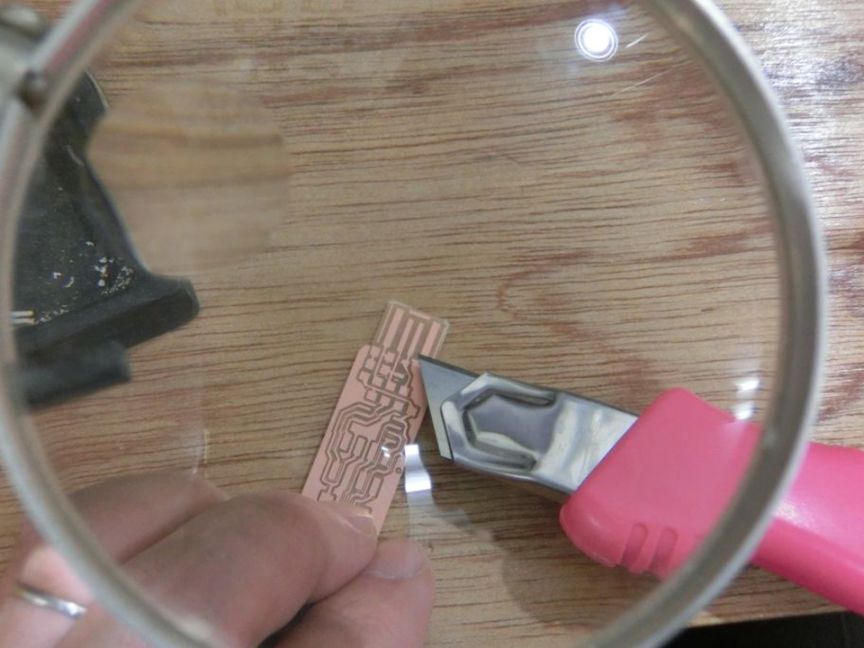
 1.4 Cutting finish
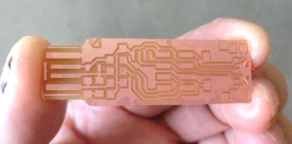
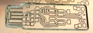
The surface of the circuit board was cleaned with detergent. Next, unnecessary patterns remaining on the substrate were removed. At first I did with a cutter, but the amount of work was much and it was serious. So I used a small router. The circuit board was completed.


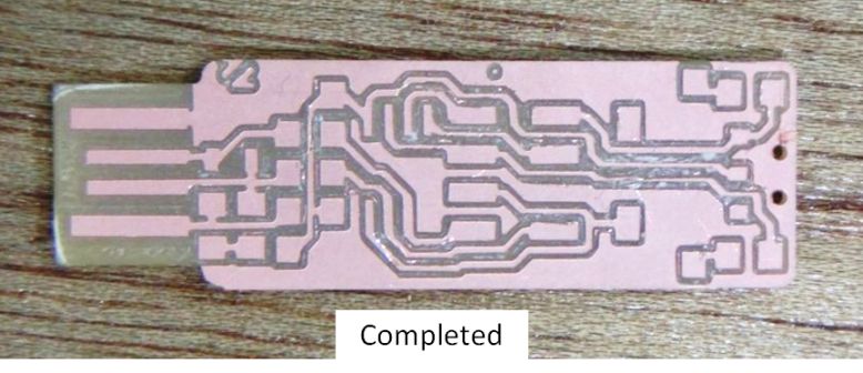
 2. Assembly
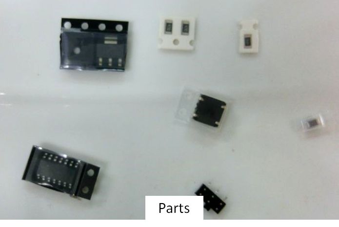
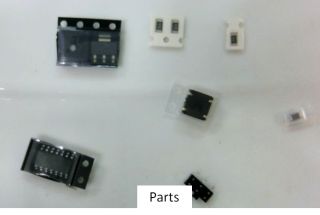
2.1 Preparing parts
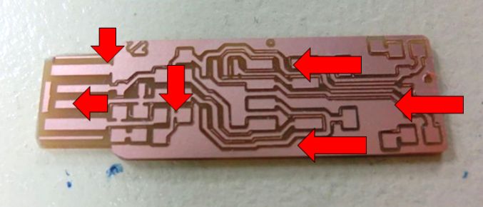
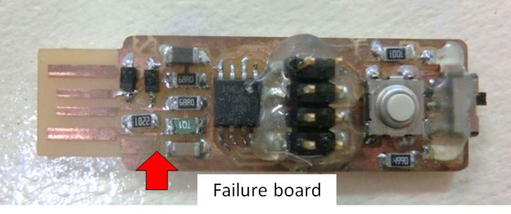
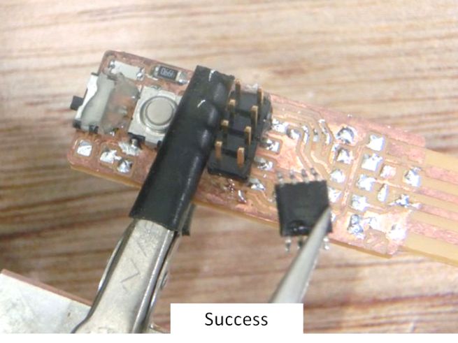
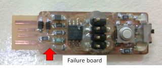
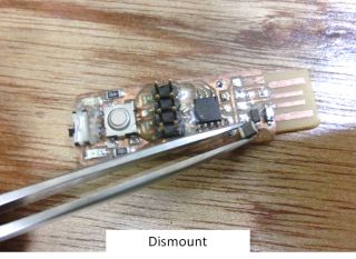
Parts to be mounted are collected according to the parts list. But a problem occurred here. There were several parts shortage. So I decided to remove parts from last year's failed circuit board of the students and reuse them. Heated the soldered part and removed the part using a solder sucker.
 2.2 Soldering
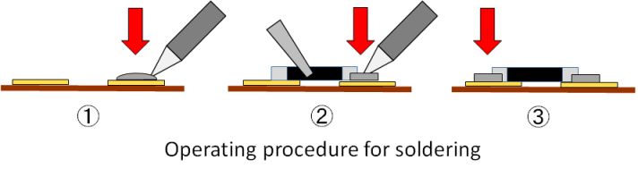
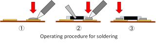
Since the parts were ready, I started to assemble. After melting the solder on one side first, the parts were soldered. Next, the opposite side was soldered. This made fixing easier.
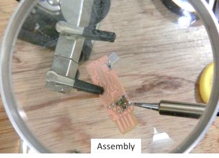
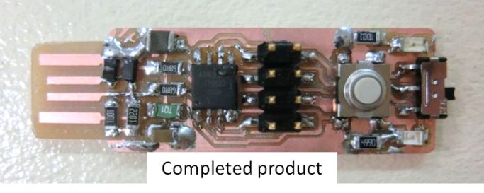
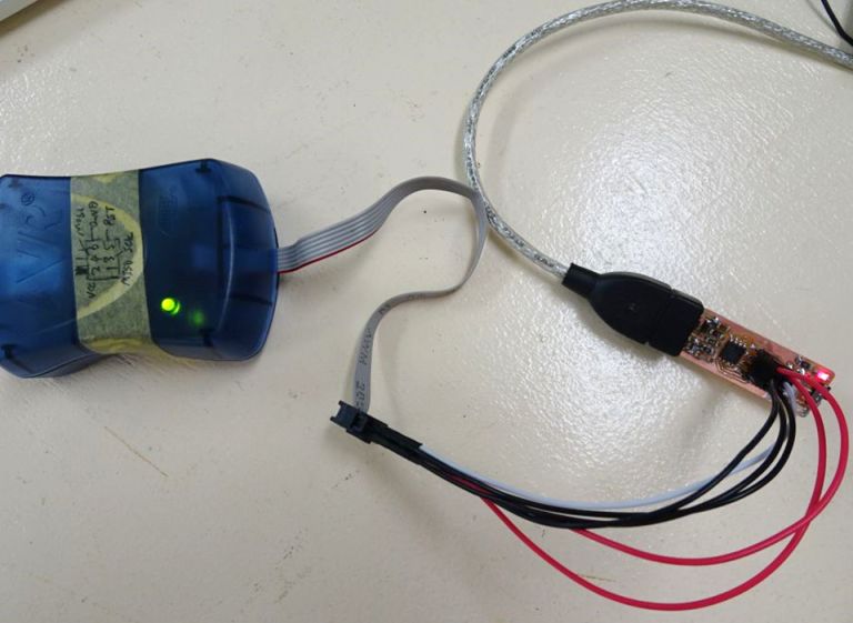
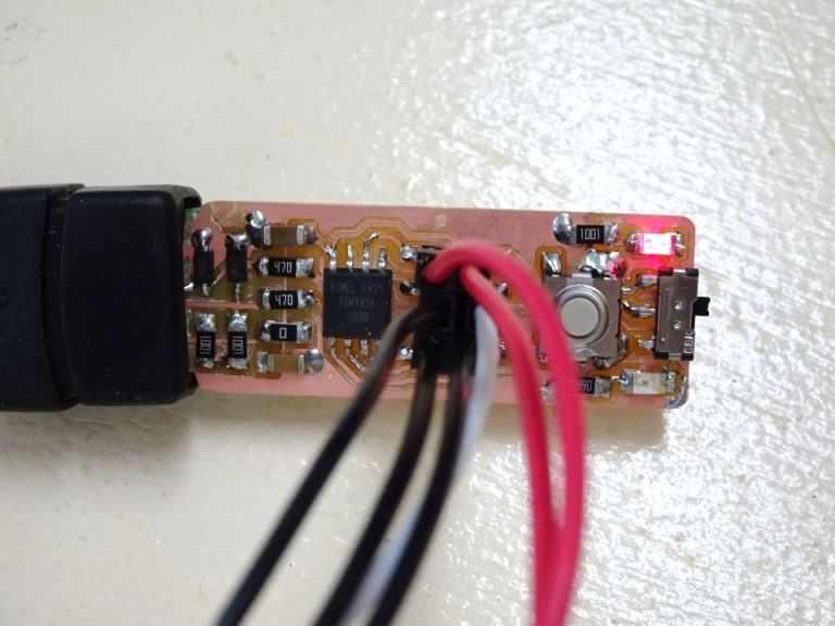
I was able to complete the circuit board as shown.
 3. Programming
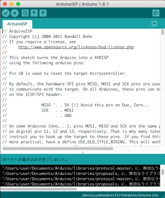
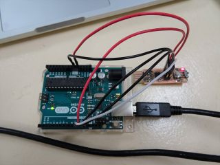
I tried Programming of FABTiny which I made. First, I connected FABTiny to AVRISP mk II. 5 V of power supply supplied to USB connector part. The red LED lights, and it is confirmed that the 5 V power supply is flowing normally. The LED of AVRISP mk II also glows green and it was confirmed that it is operating normally.


For FABTiny 's Programming, I proceeded with reference to the following pages.
-Quote:FabTiny*ISP - Programming the firmware
http://fabacademy.org/archives/2015/doc/FabTinyIsp/programming.html
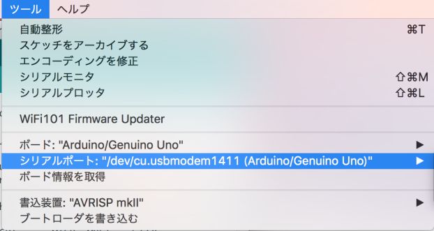
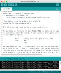
Since this page uses Arudino UNO, it did the same. First I wrote ArudinoISP on Arudino UNO. And confirmed the serial port. Next, the instructions were written from the command line as shown in the reference page. The port modified its own MAC port.

It was displayed as follows, and it was confirmed that the avrdude command worked properly.
Next, FABTiny's firmware downloaded the following file specified in the referenced page.
-Quote:simpleavr
http://www.simpleavr.com/avr/vusbtiny/vusbtiny.tgz
Following the instructions on the page, I modified the makefile. For the serial port, I changed to my MAC port.
#AVRDUDE_PORT=/dev/ttyUSB0
AVRDUDE_PORT=/dev/cu.usbmodem1411
I also rewrote usbconfig.h as indicated on the reference page.
//#define USB_CFG_DMINUS_BIT 4
#define USB_CFG_DMINUS_BIT 3
//#define USB_CFG_DPLUS_BIT 3
#define USB_CFG_DPLUS_BIT 4
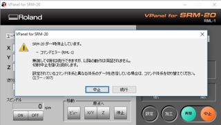
I then executed the make command. However, an error occurred as follows.I checked each file and tried it, but I can not solve it at this stage.
I plan to review each software installation and each file setting again in the future. And I am planning to make it writable.
Archive
-
Cutting pattern image (png)
-
Cutting data of circuit board pattern (rml,SRM-20)
-
Cutting data on the outer periphery of the circuit board (rml,SRM-20)
This week's assignment is over.