#16. Interface and Application Programming
Processing
This week i followed Neil advice and went into learning a bit a about Processing. Since i'm still not a big fan of programming it took a while to learn a bit about it. So started with some tutorials from the website and went from there.
My idea was to control the leds on my Hello World board, so i thought i might do something simple where i just put the mouse over a square and it would make the leds light up in one order or in the other.
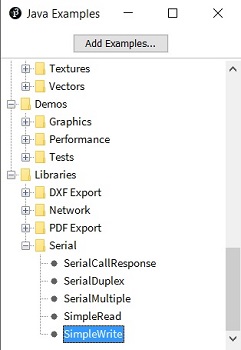
So i looked into some examples that already exist and adapted it to my needs. I choose the Simple Write from the Serials in the Libraries folder since what i wanted was to use the serial connection to link with de ftdi and send a command into the hello board.
Below there's the code i used in Processing, starts by importing the serial library after wish creats a Serial class and the data it will receive from the serial port. Then comes the window size and what will be used to interact with the ftdi, after this comes what will be processed every cicle. Starts with the background color, then comes the condition if for the left square or if is in the left, if in neither won't do anything. Below is the boolean that will test if the mouse is over the squares and if that is confirmed then it will send the letter accordingly.
import processing.serial.*;

Serial myPort;
int val;

void setup()
{
  size(350, 200);

  String portName = Serial.list()[0];
  myPort = new Serial(this, portName, 9600);
}

void draw() {

  background(255);

if (mouseOverRect() == true) {

    fill(204);
    rect(50, 50, 100, 100);

    fill(0);  // change color and
    rect(200, 50, 100, 100);

    myPort.write('H');

    println("esq");
  }

else if (mouseOverRect1() == true) {

    fill(204);
    rect(200, 50, 100, 100);

    fill(0);
    rect(50, 50, 100, 100);

    myPort.write('J');

    println("dta");
  }

else {

    fill(0);
    rect(200, 50, 100, 100);

    rect(50, 50, 100, 100);

    myPort.write('L');
  }


}

boolean mouseOverRect() {
  return ((mouseX >= 50) && (mouseX <= 150) && (mouseY >= 50) && (mouseY <= 150));
}

boolean mouseOverRect1() {
  return ((mouseX >= 200) && (mouseX <= 300) && (mouseY >= 50) && (mouseY <= 150));
}
When processing is done then comes the Arduino part so that we can program the attiny44 on the board, in this case i've once again adapted the code that was in the example, thus coming the altered code you can see below.
Started by searching for the right way to communicate with the board and found this LINK that explained exactly what i needed and that's what i've used in beginning of the code, the just used the corresponding pins and whenever the right letter came (wish corresponding with being in a certain square) it would light up in the correct order.
#include#define RX 0 // *** D3, Pin 2 #define TX 1 // *** D4, Pin 3 SoftwareSerial Serial(RX, TX); char val; // Data received from the serial port const int led0 = 8; const int led1 = 3; const int led2 = 2; void setup() { pinMode(led0, OUTPUT); pinMode(led1, OUTPUT); pinMode(led2, OUTPUT); Serial.begin(9600); // Start serial communication at 9600 bps } void loop() { while (Serial.available()) { // If data is available to read, val = Serial.read(); // read it and store it in val } if (val == 'H') { // If H was received digitalWrite(led0, HIGH); delay(100); digitalWrite(led0, LOW); delay(200); digitalWrite(led1, HIGH); delay(100); digitalWrite(led1, LOW); delay(200); digitalWrite(led2, HIGH); delay(100); digitalWrite(led2, LOW); delay(200); } if (val == 'J') { digitalWrite(led2, HIGH); delay(100); digitalWrite(led2, LOW); delay(200); digitalWrite(led1, HIGH); delay(100); digitalWrite(led1, LOW); delay(200); digitalWrite(led0, HIGH); delay(100); digitalWrite(led0, LOW); delay(200); } else { digitalWrite(led0, LOW); digitalWrite(led1, LOW); digitalWrite(led2, LOW); } delay(100); // Wait 100 milliseconds for next reading }