#15. Networking and Communications
Talking
This week again was something completely new to me, only one problem, i'm still not very good at programming so i decided that since i need to use this topic on my final project, this week i would only do the example Neil gave us and than i'll go deeper into when it comes to time.
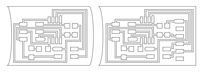
Just so that it wasn't exactly like the example, i just adapted the outside line of the schematic in order to be easier to know how to connect what.
So, started with adapting the schematic, for that i just imported it to Corel and use trace to get the outside lines. Then i remake the border so that the bridge would only be coupled with the node in only one direction, then the next node would only couple with the previous node in one direction. Below you can see what i've made:
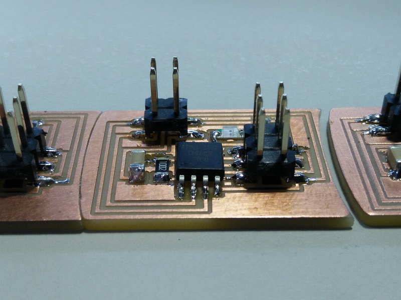
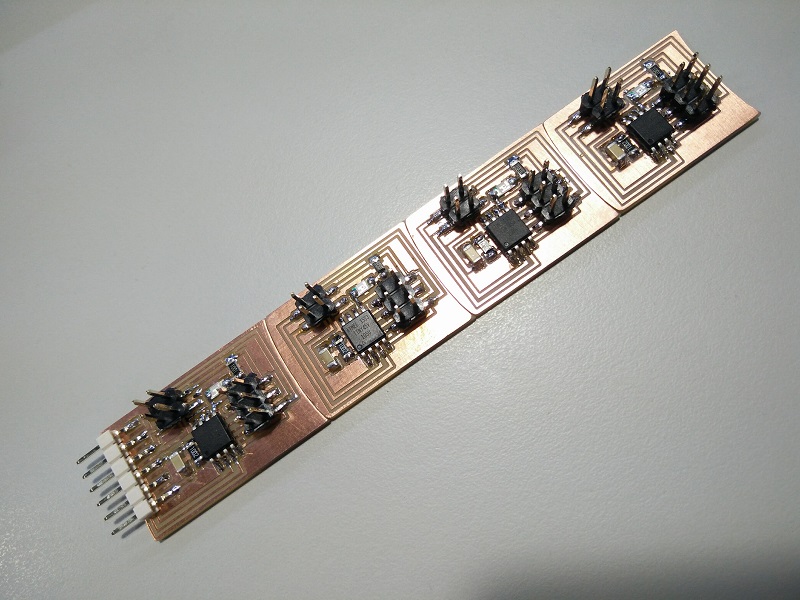
Afterwards went to Carvey to produce the boards and after a bit it came out good. Then soldering the components (still a bit of trouble with the tiny legs due to the small tremors) and checking everything for continuities with all good checks. In the next images you can see in detail how the nodes came and then how all boards fit together.
All physical part done, then came the programming. In this case i just used the files provided and modified them accordingly, i used one bridge and three nodes, so i just changed the "0" to "1", "2" or "3" and used my AVR ISP programer to burn it into the multiple tini45.
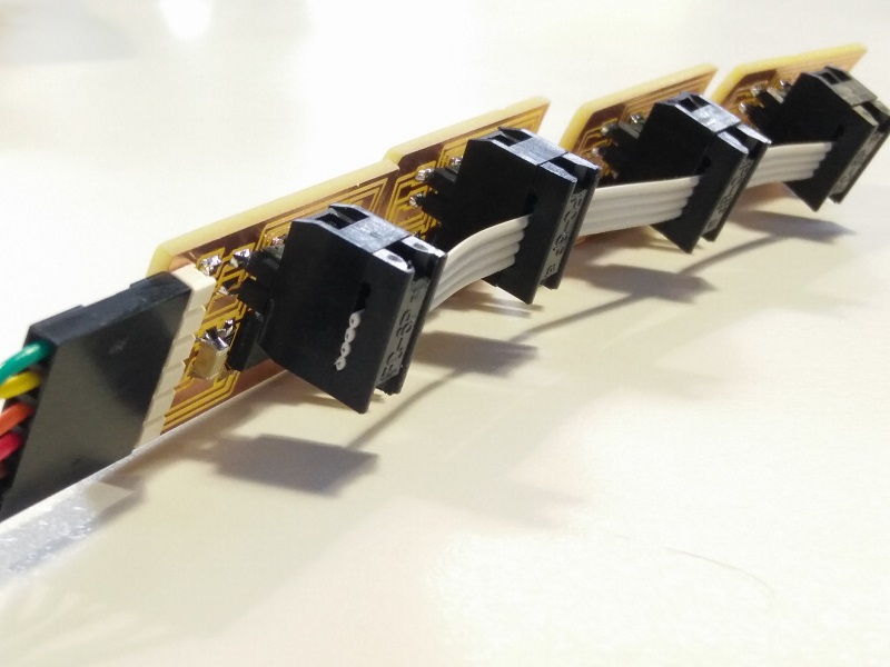
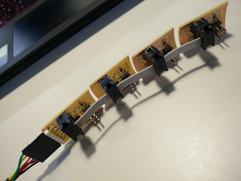
Connect all with i single 4 pins cable i made (the one you can see above) and went into the Serial Monitor from Arduino IDE and made them all blink in order (0, 1, 2 and 3). Below there's a simple video of them blinking in the order i wanted.