#08. Embedded Programming
...continuing from electronic prodution
This week i started where i left off in electronic prodution, the programmer. We need to program this programmer by using another programming equipment and in this case it's going to be a Atmel-ICE Debugger.
First started by downloading the Atmel Studio 7.0 to update and debug the programmer itself, this way i made sure everything would as smooth as possible. While the software was installing i went search for a simple answer, "how to properly connect the Atmel-ICE to the programmer?". After some trial and error i couldn't find any clear explanation for this, but happily i had some guidance from our Fab instructor, wish came in the form of a website, Humans that Make, in the learning tab, there is a tutorial named Atmel AVR Microcontrollers. At the bottom of the page there a simple and complete explanation on the connector, same as the image below.

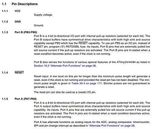
MCU datasheet
For most cases, and in particular for this one, the part that matered the most was the begining of the datasheet, the pinout and the pin descriptions. From this i could understand where to connect all LED and the button, allways having in consideration the example given in class.
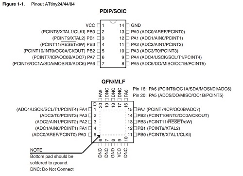
And just in case, keep in mind there's the first page where all the main MCU features are listed, here you can find most of the info about the component.

The Echo Hello-World
Last week i've redesigned the Echo Hello-World as it was suggested and in my case i added a button and 3 LEDs and my idea was that the LEDs would blink in order and the button would hold the blinking. So i grabbed the button example and modified it to my needs.
Started with including the 3 LEDs and its corresponding pins on the Attiny44, modified the pin for the button as well. Then was a matter of adding the LEDs as outputs and including them in the loop with the order and delays i wanted. The result can be seen in the video. As you will notice i made a simple case for the board with a piece of acrylic in front of the LEDs to spread the light.
In terms of the code used i based myself on the button example and added the blink, you can see it below. i've commented on the code directly.
//Constant of the button pin and the LEDs pin, make sure you see the attiny44 pinout and arduino correspondent
const int buttonPin = 2;
const int led0 =  7;
const int led1 =  8;
const int led2 =  2;

int buttonState = 0;         // variable that reads the status of the button

void setup() {

// initializes the LED pins as an output that will light up when button not pressed:
pinMode(led0, OUTPUT);
pinMode(led1, OUTPUT);
pinMode(led2, OUTPUT);

// initialize the button as an input that will be pressed:
pinMode(buttonPin, INPUT);
}

void loop() {

// reads the state of the button value:
buttonState = digitalRead(buttonPin);

// checks if the pushbutton is pressed. If pressed is HIGH and the LEDs will light shut down at the end of the cicle

if (buttonState == HIGH) {

// turn LED on (HIGH), delay then off (LOW):

digitalWrite(led0, HIGH);
delay(100);
digitalWrite(led0, LOW);
delay(200);
digitalWrite(led1, HIGH);
delay(100);
digitalWrite(led1, LOW);
delay(200);
digitalWrite(led2, HIGH);
delay(100);
digitalWrite(led2, LOW);
delay(200);

} else {

// turn LED off (LOW) when the button pressed:
digitalWrite(led0, LOW);
digitalWrite(led1, LOW);
digitalWrite(led2, LOW);
}
}
Files to download:
fts_firmware_bdm_v1
cad_avripsusb_case
cicle_final
cad_ehw_case