#04. Electronics Production
Technology
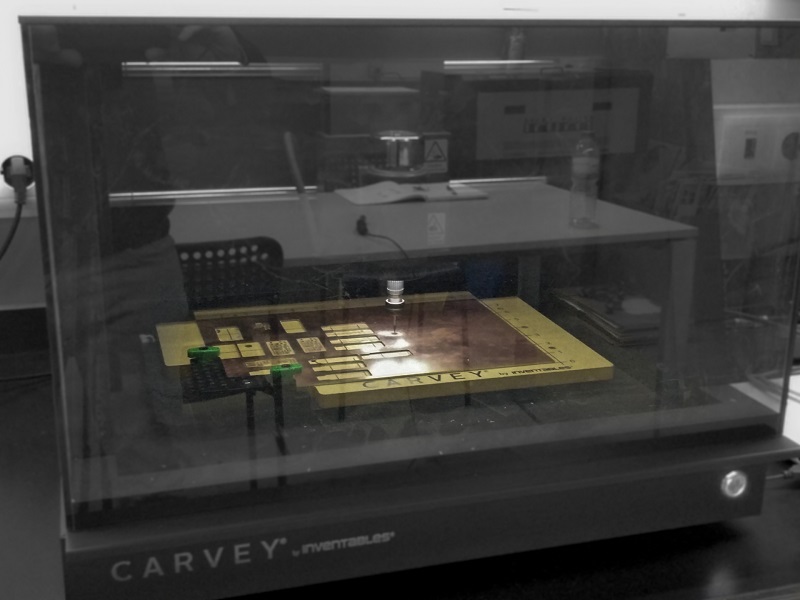
For this week we were asked to produce a FabIPS and for that we could use a certain number of diferent techologies. In our case at the FCT FabLab we can only use machining and for that we have a Shapeoko 2 and a Carvey both by Inventables. The first one was a kit bought a couple of years a go and is a very simple equipment with 3 axis controlled by an arduino with a gshield. On the other hand we have a month old Carvey, wish is the machine we ended up using to produce our pcbs.
From digital to physical
Started with some experimenting since i never used the Carvey before so in order to make it right i started with a little testing first. After some advice from our remote instructor Luís Carvão we decided to simply go for it and carve! First and very important, the Carvey uses a specific app, the Easel, its a very simple, very user friendly app where you can either draw directly on the browser app or you can import an SVG, Gcode or trace an image. We started by trying importing the Gcode and to generate the desired code we used Fab Modules as follow:
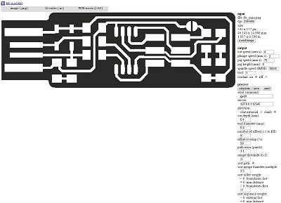
Imported the Gcode on Easel but unfortunatelly we got into some code problems as the exported gcode couldn't be recognized by the app and kept on giving errors, so decided to use the trace from the app directly on the png. The outcome from this wasn't detailed enough for what we needed since the tracks ended up beeing mixed and not as like the png. Lastly, we tryed the svg import and that did the trick.
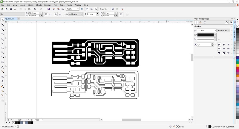
To get to the svg file i started with the png wish them i uploaded it to Corel Draw where i traced it and did it perfect enough, afterwards was just a case of cleaning the extra lines and just filled with black the space between tracks after wish i just exported it. Bellow you can see an example of the trace and then fill.
With this svg file was just a matter of importing it on Easel and defining the parameters:
- The position in the work area;
- The material you will be carving (it has some presets already);
- Choose the bit size (0.3mm for the copper and 0.8mm to go through);
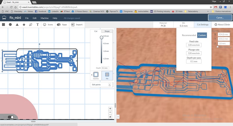
- Change the cut settings if you don't want to use the recommended (feed rate, plunge rate and depth for pass);
- As you can see in the image below i usually use: FR 120(mm/s), PR 120(mm/s) and DP 0.1(mm/s) (or 0.3 if 0.8mm bit);
- You can also choose the dimension of the material and the Z dimension is CRUCIAL;
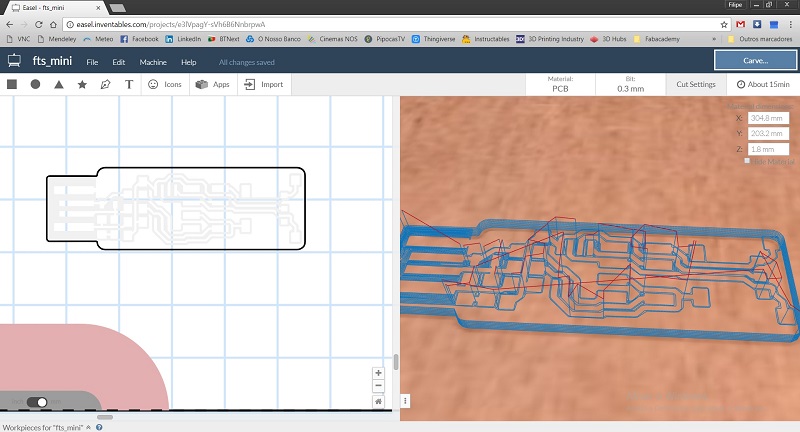
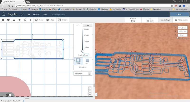
Now for the milling parameters, in the easel you can choose fill, outline, inline or on path. For the copper removal i used the fill as seen in the first image where it will only remove 0.1mm of material (sometimes it would be usefull the remove less but the Easel can't remove less. For the removal of the board i selected the outline and changed the bit size to 0.8mm as well as changed the cut settings. After all of this, you can just press simulate and you get a simulated path and time it will make to carve you pcb (according to experience it will take 1/4 more of what it says).
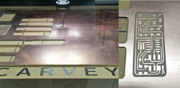
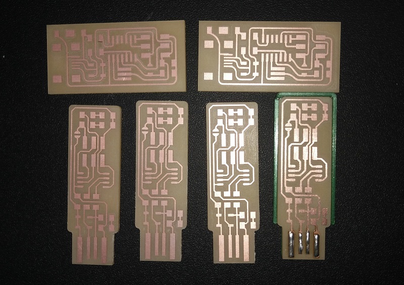
After about 30 minutes to fully carve each pcb, we ended up with some beatiful and defined boards to solder the components on.
Soldering
After fabrication it was time for soldering all the components, started with the processor, those tiny legs at first were a little dawnting but after a bit of practice it went smooth. In the first image you can see one of my first soldering jobs of this kind, been perfecting ever since naturally and i've redesigned Brian's programmer to make it a little bit smaller.
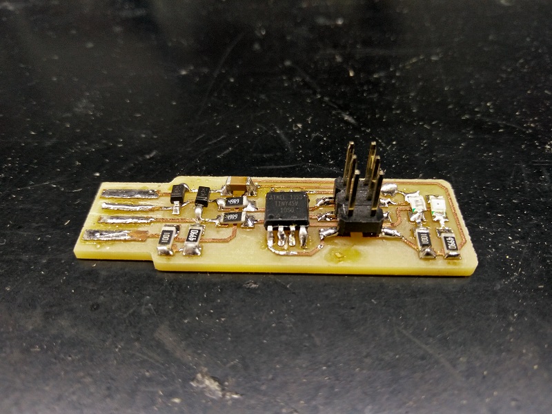
As advised allways solder one side of the component, push it down with a tweezer, reheat the solder to make the component flat with the pcb, then just solder the other side and that's it. Make sure you orient the component the right direction as a diode with the wrong polarity.
After all done do confirm all continuities and make sure nothing is shorted before you power it so that you don't burn anything. And just to be safe you can confirm the resistors as it can easily swap one without noticing it.
Programming
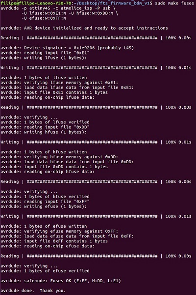
Before going to the hello world board i wanted to finish programming the FabTinyISP so that i could use it to program the first one. So, started by changing to linux SO, where i could use the avrdude easier and took the necessary steps to install and update it. For that, i followed Brian's webpage from wish i used "sudo apt install avrdude gcc-avr avr-libc make". After this i went to download the firmware for the FabTinyISP, there i edited the file called "Makefile" replacing the line "PROGRAMMER ?= usbtiny" with "PROGRAMMER ?= atmelice_isp" as well as making sure the "MCU = attiny45" was really the Attiny45.
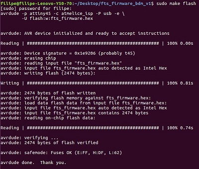
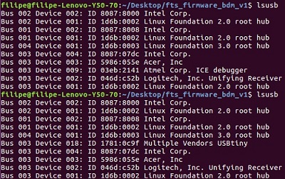
That done it was just a matter of going into the folder were the firmware was, then using "make flash" and after getting the info that uploaded successfully did not occur any errors i just used "make fuses". After the last make i removed both programmers and then just connected the FabTiny and used "lsusb" to check if it appeared and there it was "Multiple Vendors USBtiny". Then just removed the jumper and it was ready to use.
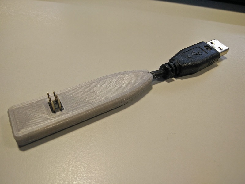
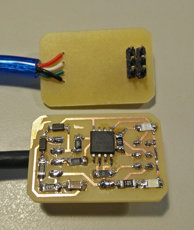
Unfortunatelly i haven't taken any photo before i closed the programmer with the 3d printed case but it is exactly the same as Brian's being the only difference the fact that i soldered an USB cable to the pads. You can see the results below, a solid and sturdy programmer.