What's Electronics Production?
As electronics became an essential part of every device around you; engineers, scientists, and makers have adopted a set of mechanisms and procedures to facilitate and standarize the making of electronics board. Electronics production is a general term that includes all the proccesses from fabricating the Printed Circuit Boards (PCB), soldering components, and finishing techniques. This week assigment is to use CAM tools to fabricate and solder a In-Circuit Programmer.
Step 1: Getting Ready
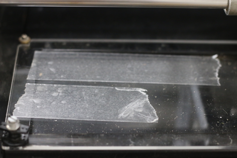
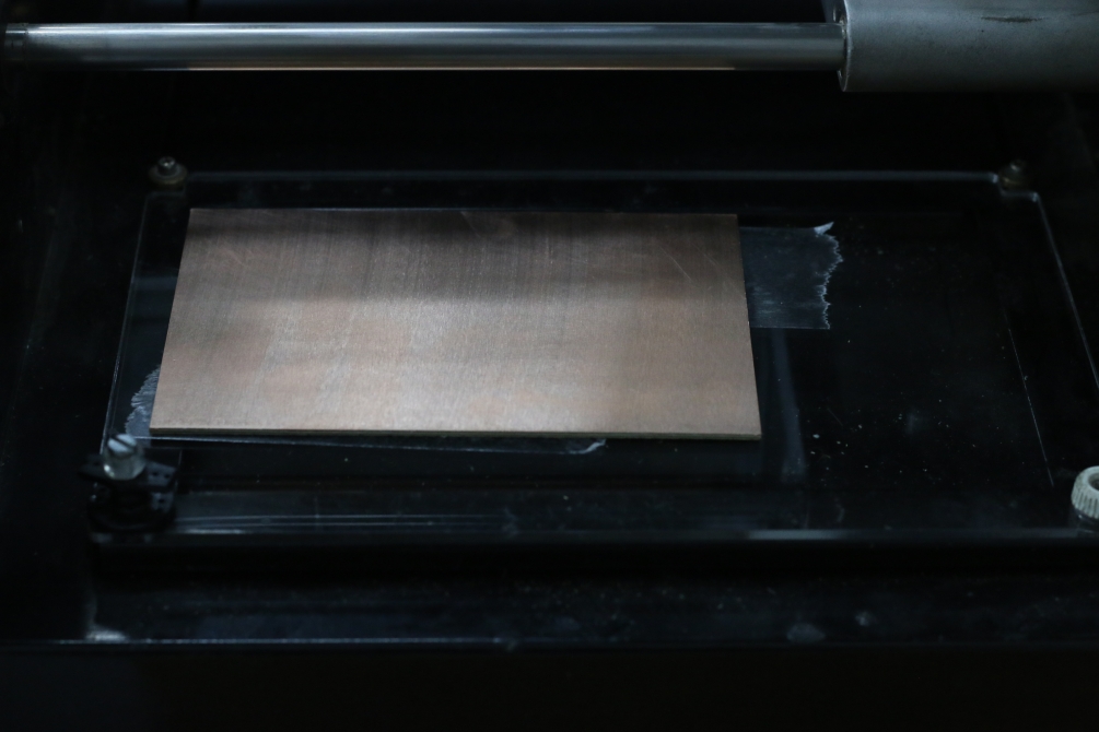
This week I'm using Modela Roland MDX-20 milling machine, it's a bit old version but it works fine (fingers crossed). First thing to do is to clean the bed of the machine. I have used the laser cutter to cut a new sacrifice layer -using 3mm acrylic- to get a clean finish.
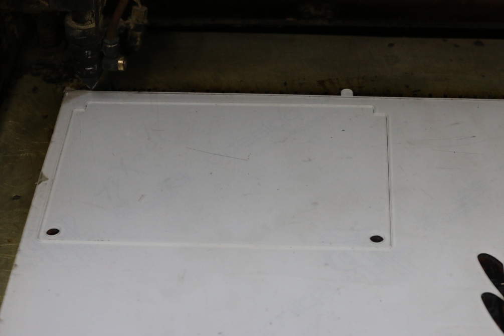
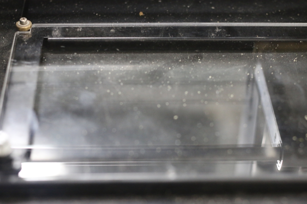
Then adding some double-face tape to hold the copper board in place. Don't use too much tape tp be able to take the board off when you finish. Apply some pressure to make sure that the whole board is flat.
Step 2: Machine Setup
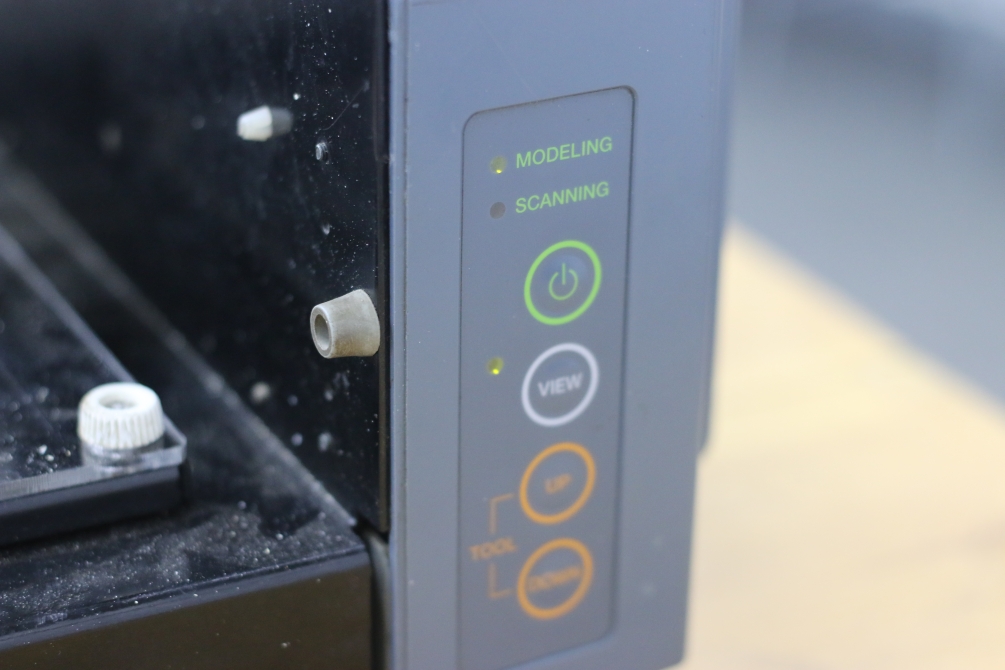
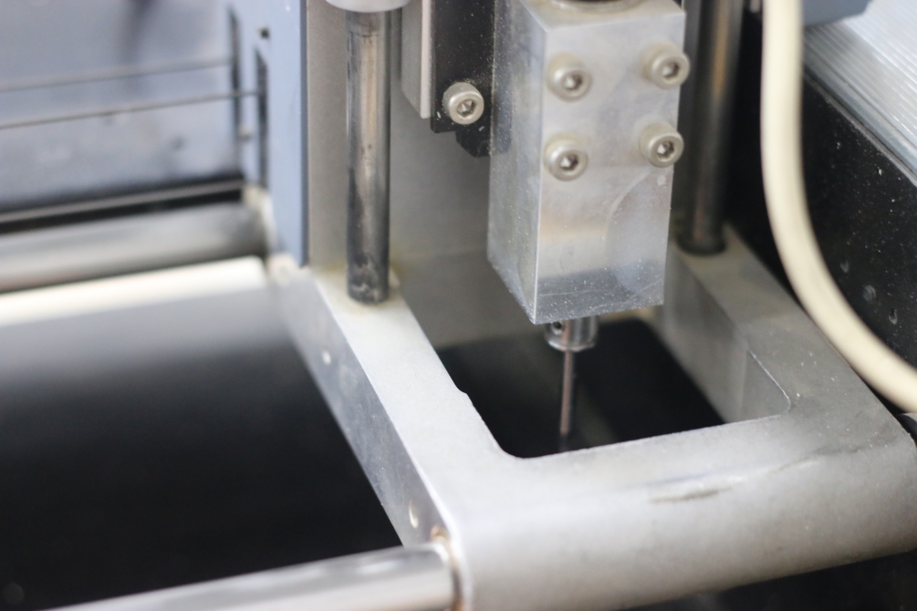
Well I remember my first time using this machine, it really took so much time to get used to it, we call at Fab Lab Egypt "Mozela" which an arabic word for "humiliating", because it was too hard to learn how to smoothly run everything. Anyway, now we will install the endmill, we will use 1/64" to cut traces and 1/32" to cut out the board. Before anything, make sure that you are in the View mode, otherwise click on the View button, the machine will move home and stop. Then slide the endmill gently and leave a resonable part inside the machine -we will zero the z-axis later- then gently tighten only one of the screw, don't tighten both because the two screws will start pushing each other. Then press the View button again, the machine will move to the last rememberd location. Now it's time to set the z-axis, there're two ways to do this. The first way is to use the arrow buttons in the front chasis to lower the spindle tell the endmill just touch the copper board, remember just touch. The other way, which I prefer, is to un-tighten the screw then gently push the endmill down till it touch the copper board -don't let it fall-, then re-tighten the screw.
Step 3: Installing Fab Modules
If you are using linux -and you better do- you'll need to install the fab modules on your device, or just using the online fab modules. However, I perfer using the local version because the online one is a bit buggy. you can find the full documentation on how to install the Fab Modules here.
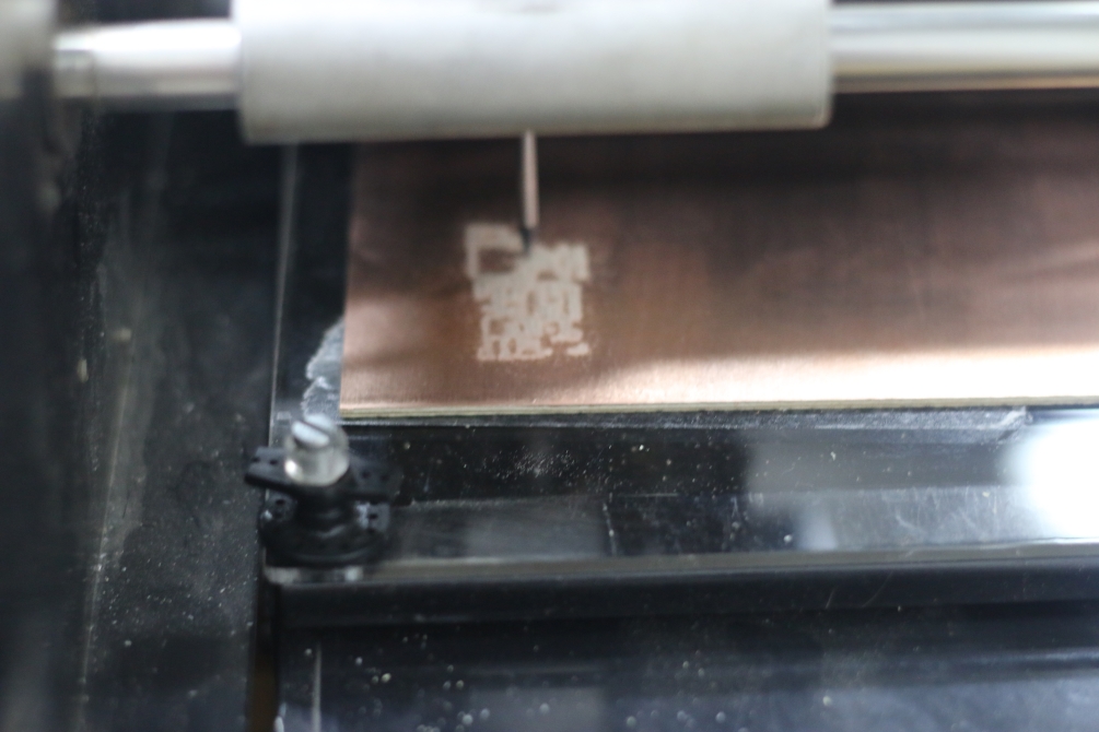
Step 4: Milling Time
If you have successfully installed the fab modules, you'll be able to run it, using the command:
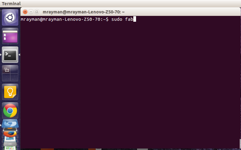
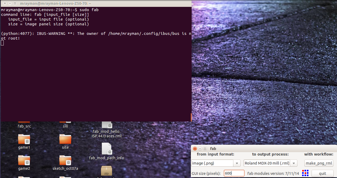
We will start with the traces, I have downloaded the version that Prof. Neil made. Start by loading the image for the traces.
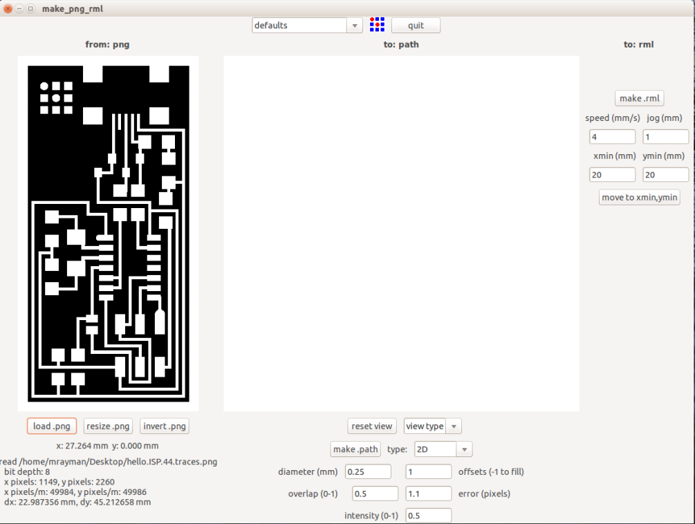
Then choose mill traces operation, I'm using the 1/64" endmill so make sure you are choosing the one that you use. Then you can set the parameters. I have changed the offset to 2, to prevent traces overlapping, and adjusted the speed to 2mm/sec because I'm using a weak endmill, and I don't want it to break.

When you finish editing the parameters, click "make path". Check the preview for any problem, then move the machine to the start point, choose x,y coordinates then click "move". When you are ready, click "make .rml", then "send it!", a new window will open up then click start milling.
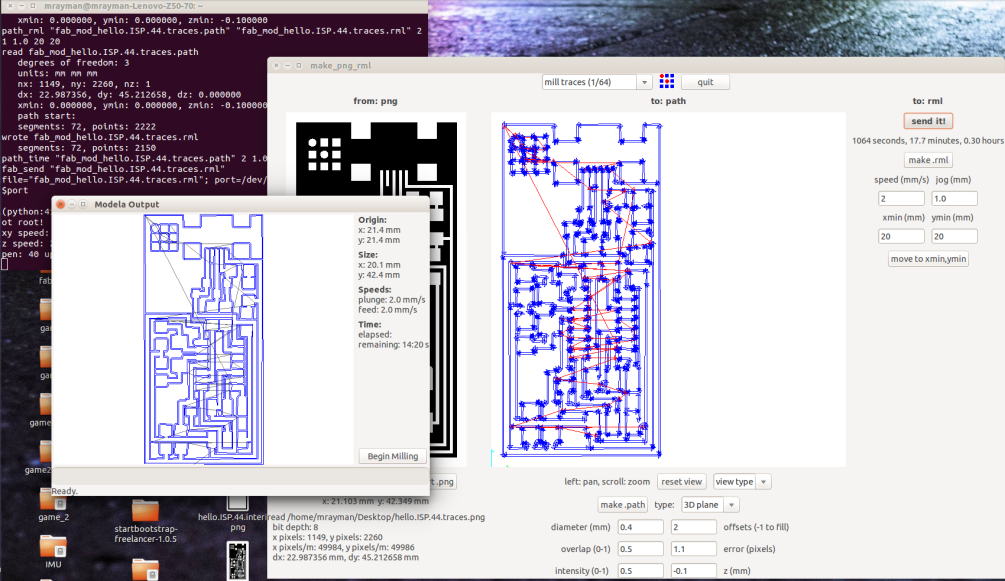
The whole process should take around 15 min. Then you'll have a nice and clean finish.
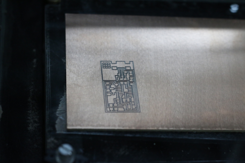
Step 5: Cut your board
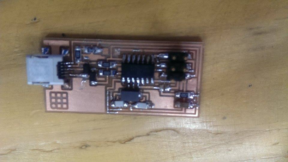
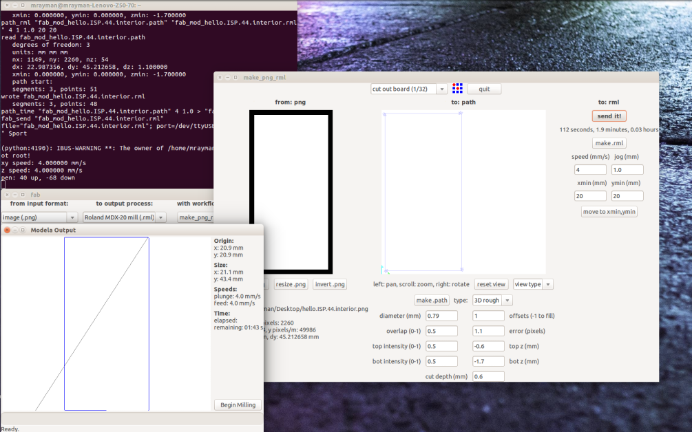
When your machine finish, press the view button, change the endmill to the 1/32", then re-zero the z-axis. Remember don't change the start x,y coordintes to perfectly locate the cutting image. Now load the outline image, and choose "cut out board" process, and repeat the same steps; "make path", "make .rml", "send it!", and finally "start milling". The cutting process is a lot faster, it took around a minute. And now I have a clean perfectly millied circuit.
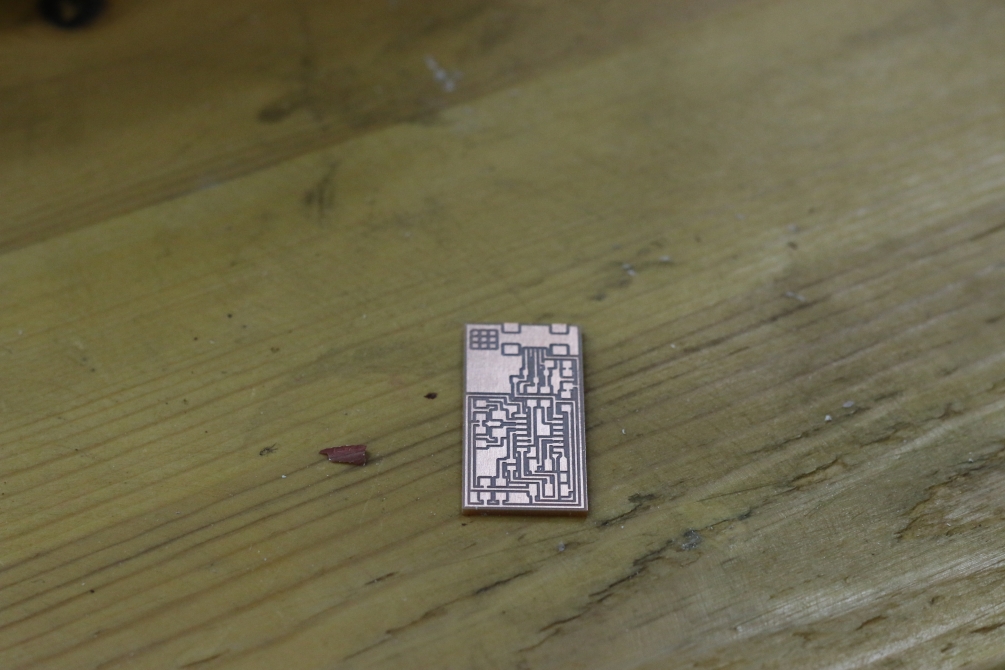
Step 6: Getting Ready for Soldering
After finishing the machining, if you had un-clean cutting and the remains of copper still attached, you might use a soft sand paper to clean the board. Then wash the whole circuit by water to clean it (yes I'm not kidding), make sure to completely dry it before soldering.
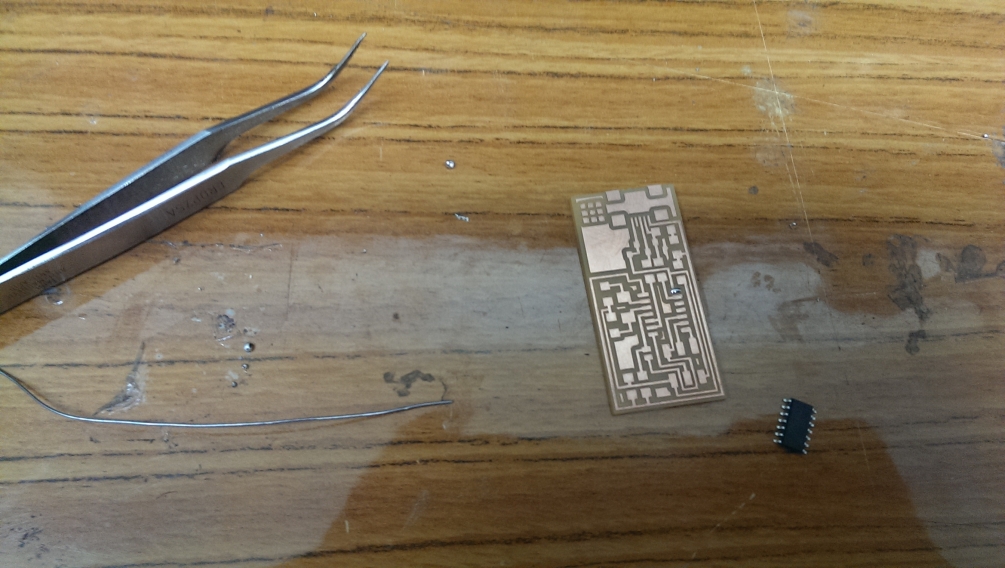
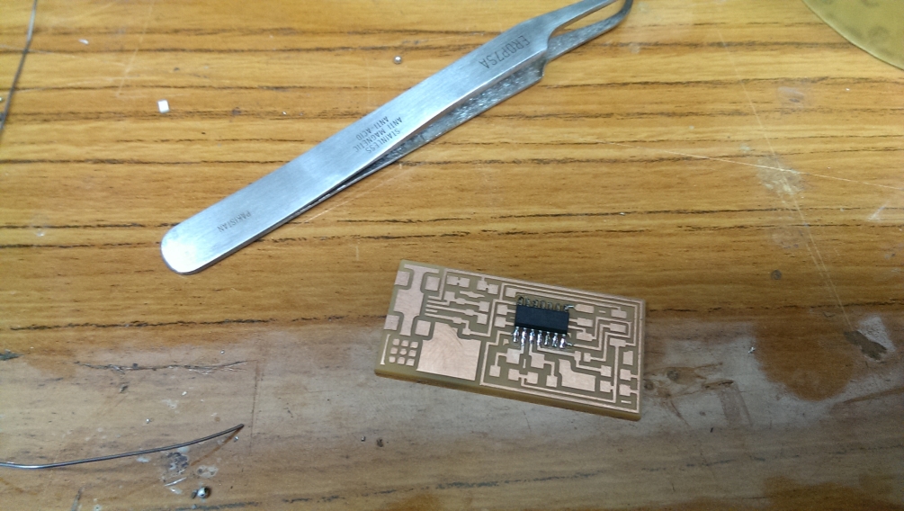
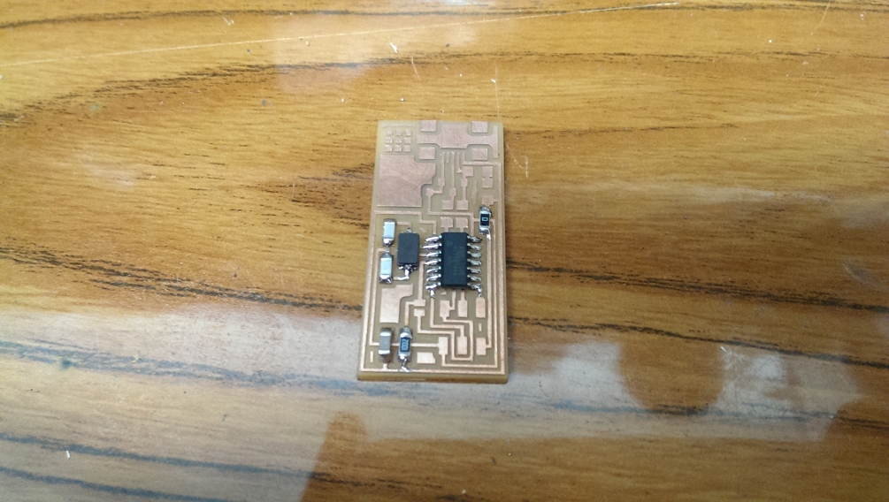
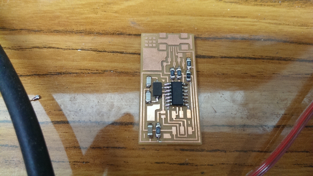
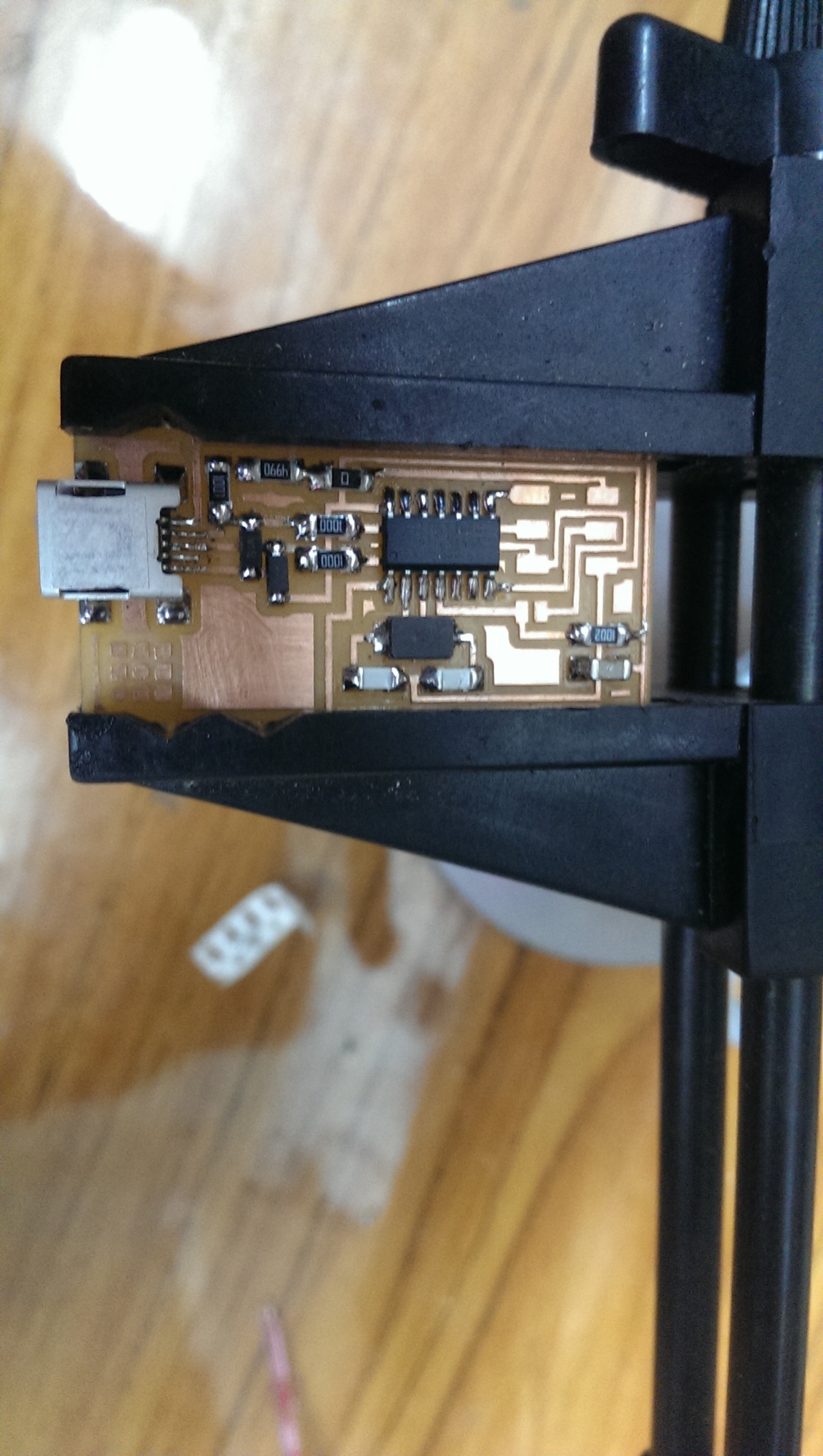
Step 7: Soldering the Components
Before soldering, you should get your bench ready. Keep the soldering station powered and beside you, get the components ready and you might need to clean your bench not to lose them. Then start soldeing from inside out, and start with the smaller components. These are some tips that might help you: 1. Use a circuit holder. 2. When soldeing large components (i.e. the Attiny 44) start by melting some solder on one of the pads, then use the iron to solder this pin of the MCU, usually start with pin 1 to get the orientation right. After that, start soldering each pin. 3. Don't apply too much heat. Keeping the soldering iron in contact with the copper for too long might rip copper off the board becuase of the excessive heat. 4. Remember to check the polarity of diodes before soldering them. 5. The USB is the most tricky part.
Step 7: Flashing the MCU
Now it's time to upload the firmware to the board. You will find the documentation made by Fab Academy here.. When you download the firmware to your machine, move to its the directory then follow the commands
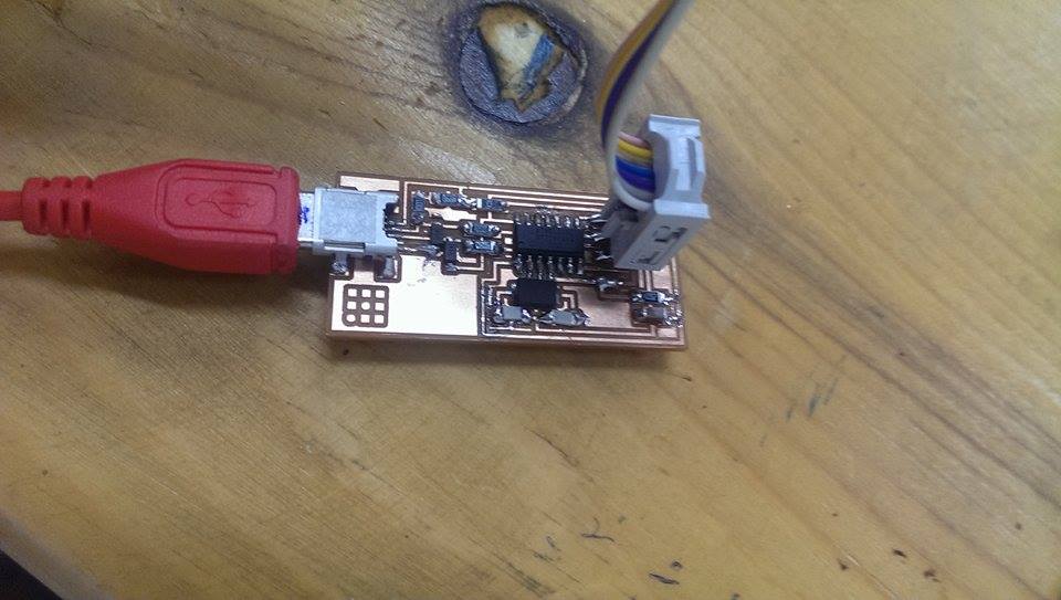
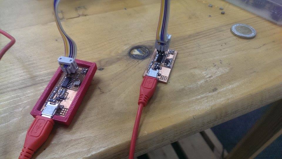
Connect the USB for the two boards, and connect the ISP cable.
gedit Makefile
then edit the the crystal speed. I'm flashing my circuit using another FabISP circuit made by my friend, thus I've un-hashed the line containing "usbtiny", and hashed the other one.

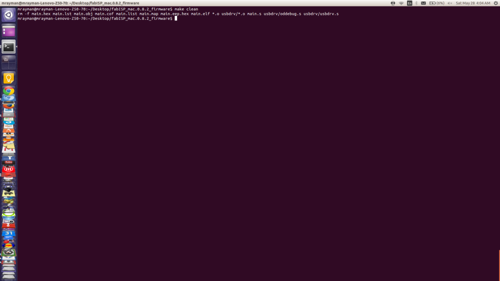
then make clean
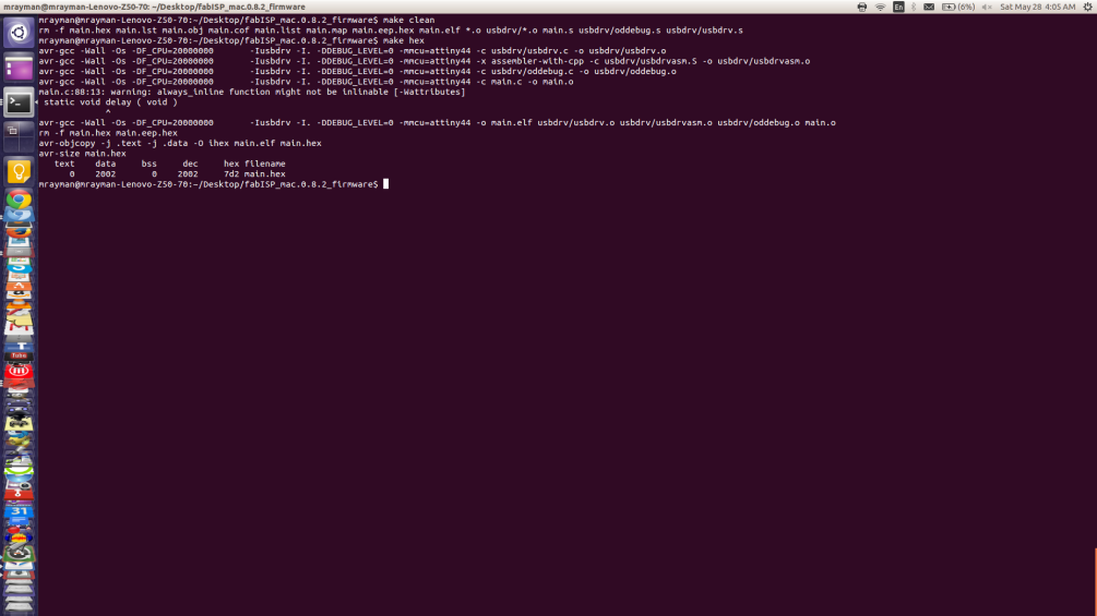
then make hex
then sudo make fuse, remember to 'sudo' your command otherwise it won't work.
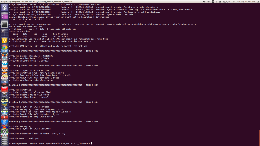
then make program
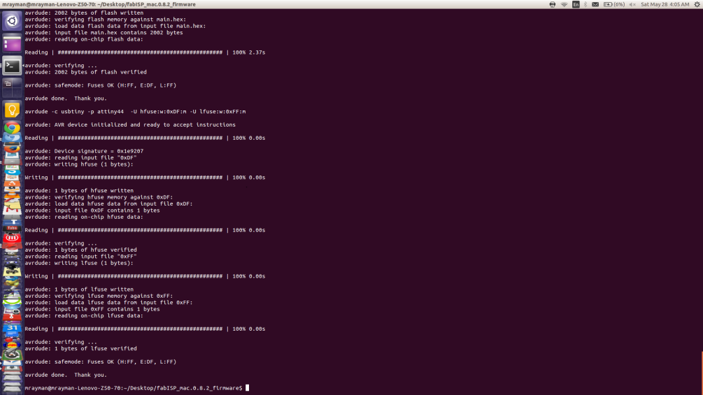
If you got no problem messages, you're lucky. If you got problems, re-check that you have connected the ISP cable correctly.
Step 8: Removing the jumpers
Now you'll have to remove the jumpers. The one soldered at the bottom, to turn into a programmer. And the zero ohm ressistor on the top to stop the ISP header from draining power.