What's CAD ?
Computer Aided Design, or CAD, is a bunch of concepts and techniques of how to use the power of computers and graphics processors in design and simulations. CAD is a part of the Computer Aided Enginnering field. There's a variety of CAD Softwares and tools that you can use, it starts from free sketching softwares (like Paint) to sophisticated mechanical simulation softwares (like ANSYS). Some softwares has a graphical interface, and some are based on scripting shells (like OpenSCAD). You can categorize CAD softwares into Raster and Vector formats. Raster formated design and raster-oriented softwares (like paint, GIMP, Photoshop) form the design as a huge combination of pixels, as a result the resoultion of the design or image is dependant on the size, whenever you enlarage the design or zoom in the image/design "pixelate". On the other side, vector formatted designs save the data as vectors (startpoints, endpoints, lengths). Each format has different settings when you start working with the machines.
Project Idea
I think that everyone, especially you, have used a robbotic kit or read about one. And it's popular because it enables everyone to start building robots without any background, and it keeps teaching you many concepts till you become an expert and you start making your own robots. In my project the concept is the same, but I'm working with machines instead of robots. Machine Designing can be very tricky, and I have met many developers who failed to complete building their own machine, either because they can't find the right materials, or due to lack in experience. My Project "MultiFAB" is a universal machine construction kit, which you can use to build your own machine. My scope for Fab Academy is to build a universal platform/mechanism that can be used to make 3D printers, Laser Cutters, and CNC milling machines. Here's my basic plan for the project.
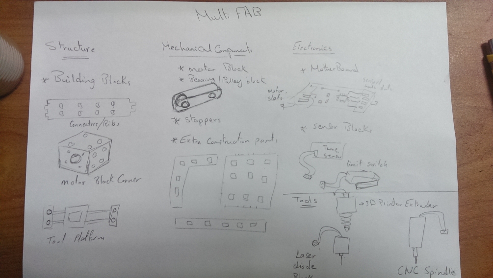
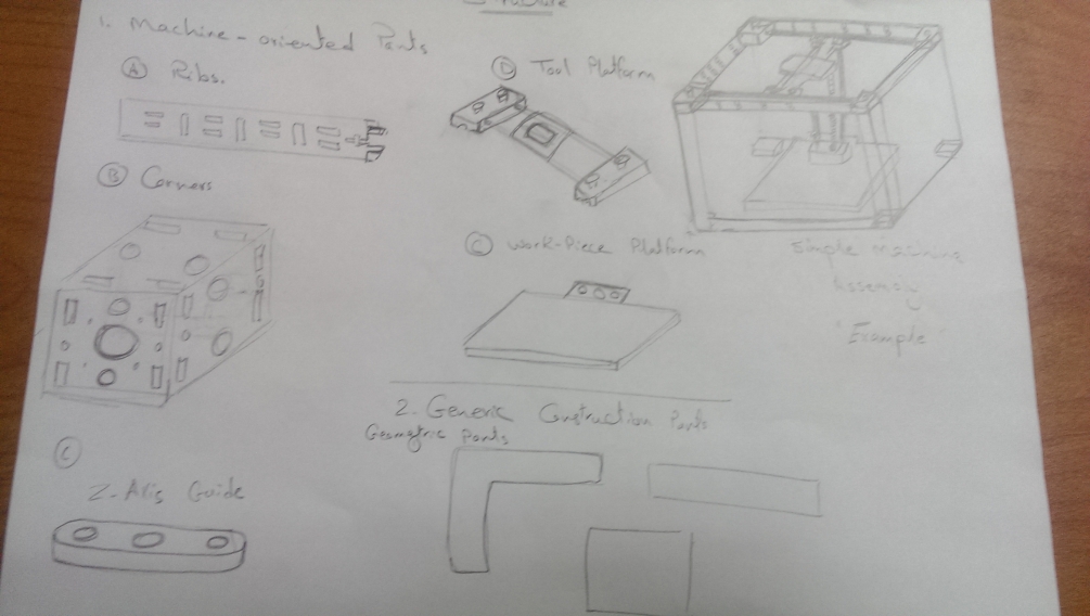
Step 1: Free-hand Sketch
I have made a free-hand sketch to illustrate my idea.
Step 2: Raster Drawing
For my project there was no need for raster drawings, and I have already made a simple -and idiot- illustration using GIMP, for now I'm pretty satisfied with the free-hand sketches. However I was thinking about a logo for my project so I used GIMP to design a draft for the logo.

Step 3: vector Drawings
Now I have a clear understanding about my project, I'm still working on the details, I have started designing the platform base. First thing that you want to learn is joints, I want my construction kit to be modular and easy-to-build. I have searched a lot for the best joints and I have chose what I call "Tee slot screw joint" on MAKE cnc joinery panel
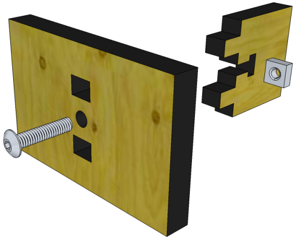
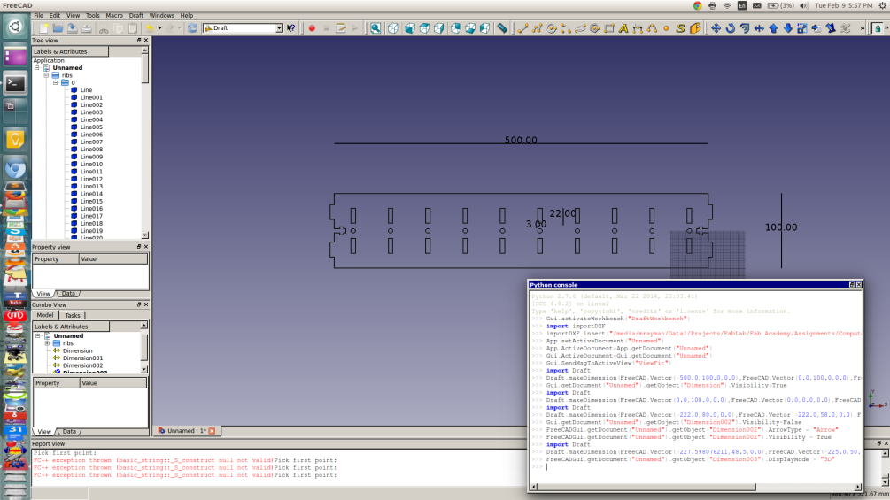
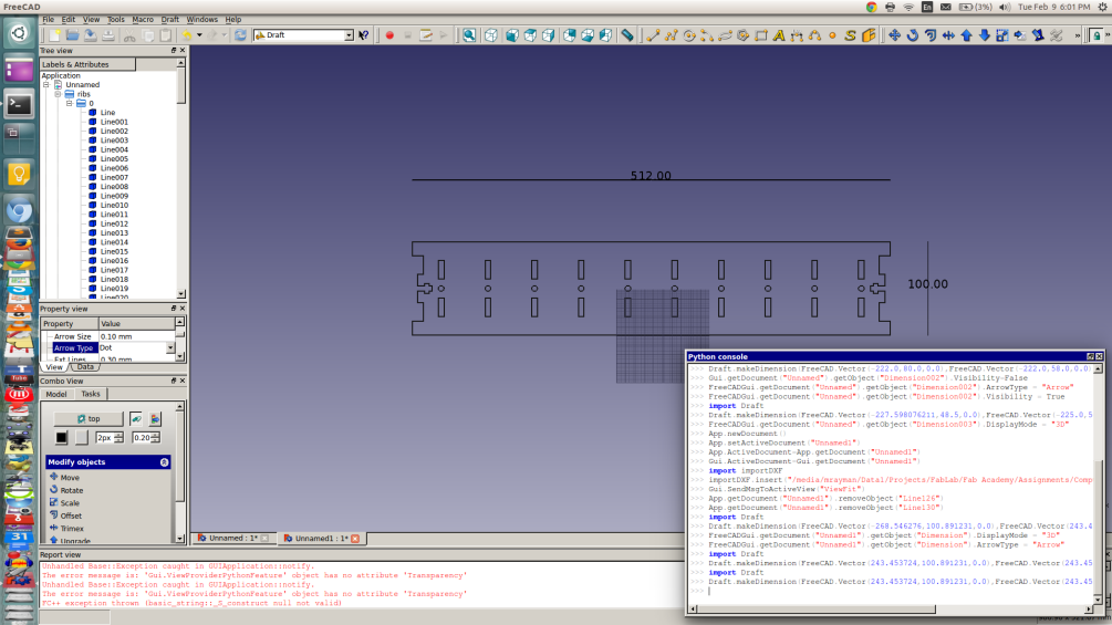
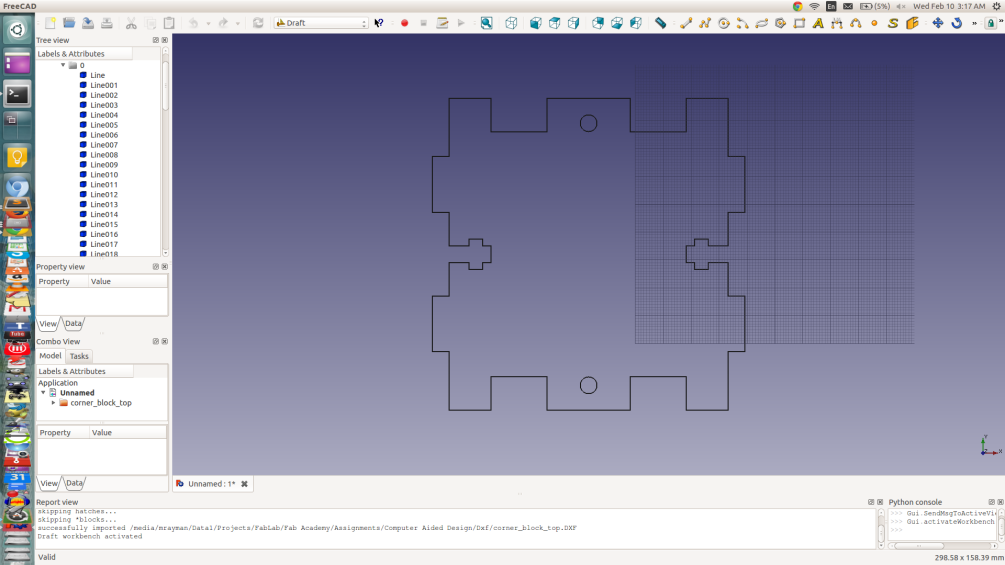
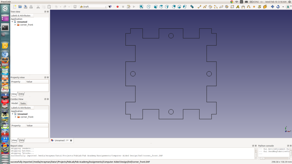
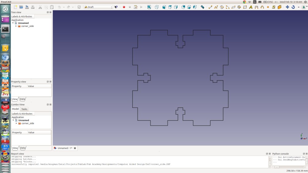
This joint is strong enough to hold different parts together, and requier no glue, and it's easy to disassemble. After that I have started searching for the right material, I may confused between using Acrylic Sheets or thin Almunium. But I decided to stick with 6mm Acrylic sheets, because it's cheaper, easy-to-manfacture, and avaialbe. Then I have used FreeCAD to design a 2D sketch for the platform.
Step 4: 3D Sketches
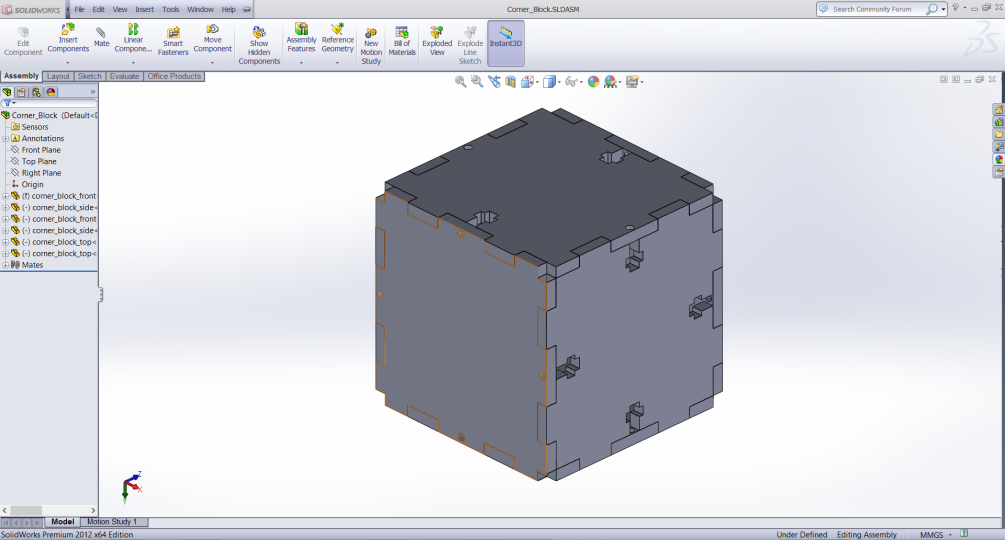
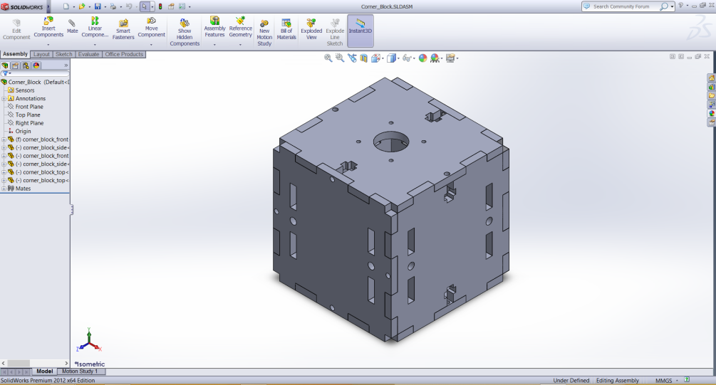
After that I started moving into 3D, I wasted too much time in this step as I had to fix some problems in winodws, and I ended up re-installing windows and SolidWorks. Using solidworks, I have imported the 2D sketches made by FreeCAD, then extruded the parts to get a 3D parts and then made an assembly to get the following 3D Design.
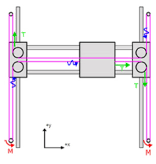
After that I spent some time thinking about the best mechanism that I can use for my machine kit. I decided to use the "H - Belt" structure. Becuase it has a high complexity/modularity ration, we can easily modify it to fit with different structures and it's not that difficult.
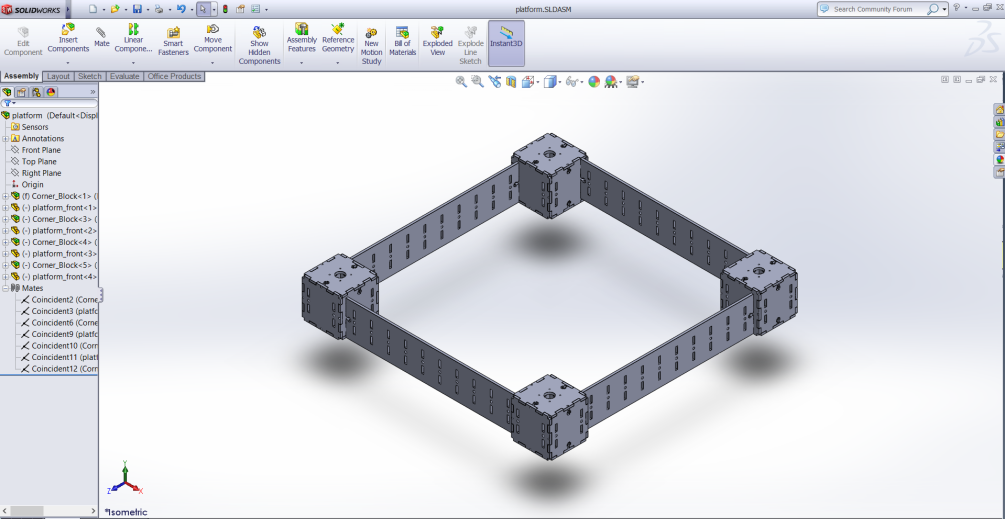
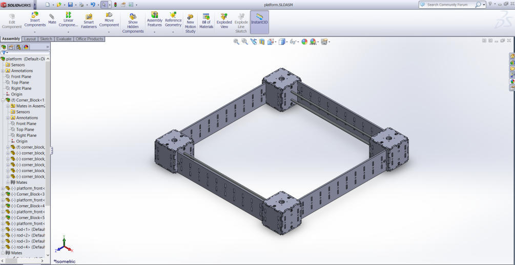
After that I have assembled the whole platform, and added some mates and relations to get this final 3D model.
Then I have designed some rods to connect between the corners, which will later contain the stepper motors for the motion.
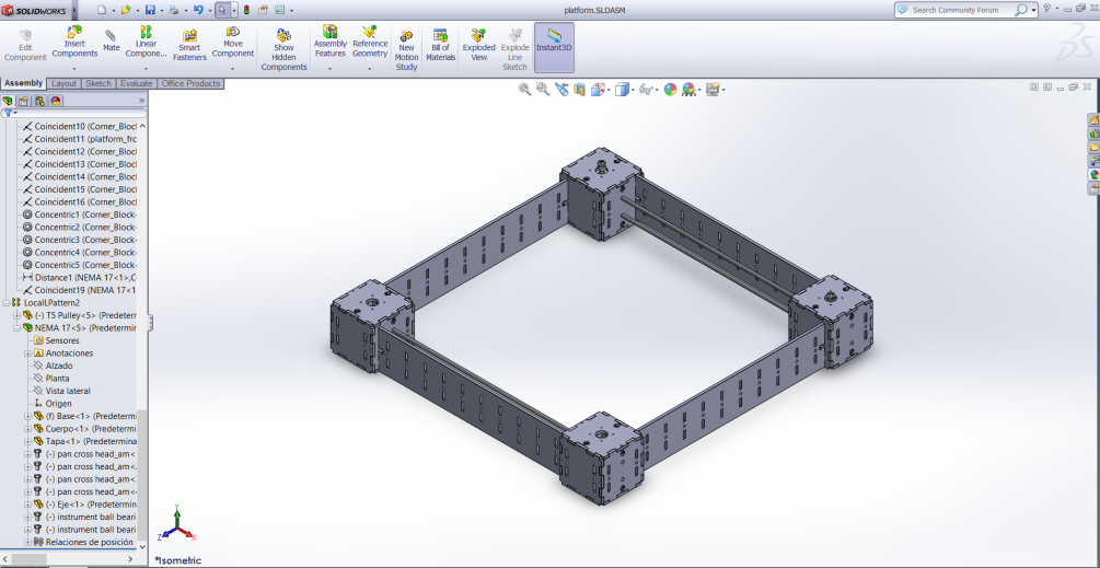
Then I have downloaded a free 3D model for the stepper motor, from GrabCAD, and I have added the motors to the model to get the following:
Finally I have used SketchFAB service to get a 360 view for my project. Remember you have to export your design as STL before using SketchFAB, and export the whole assembly as one part (I have spent two hours looking for this option, you'll find it in the "export options" drop down menu in the export dialog).
Platform by mrayman on Sketchfab
Corner Block by mrayman on Sketchfab
Useful Links.
Here is a puch of websites and softwares I have used to make my assignment.