Input Devices, so What?
In any device, machine, circuit, or system you use; all the data are either input or output signals. And to be able to master electronics and to automate machines, you'll need to learn how to control inputs and outputs. This week, and the after next week, we'll discuss the inputs and outputs using the AVR microncontrollers. Again, you will need to visit the datasheet for the ATtiny 44 datasheet to check I/O ports, ADC and DAC. To save time and efforts, I have designed one circuit containing input and output components. This week I'll focus on the input part, then we will discuss the output later.
Step 1: Drafting the Idea
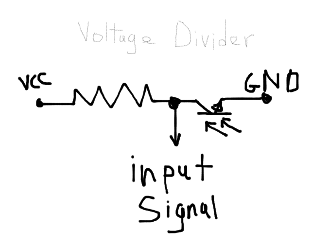
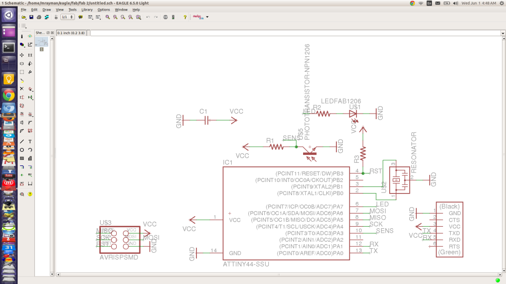
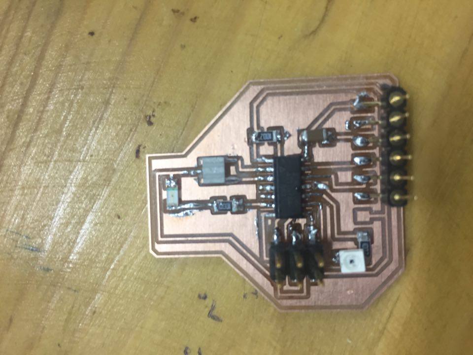
This week we will design and input circuit using ATtiny44. The idea of the circuit is to control the brightness of LED according to the intensity of light. I'm using a phototransistor as a sensor to measure how much light is falling on the board. The underlying concept is voltage divider.
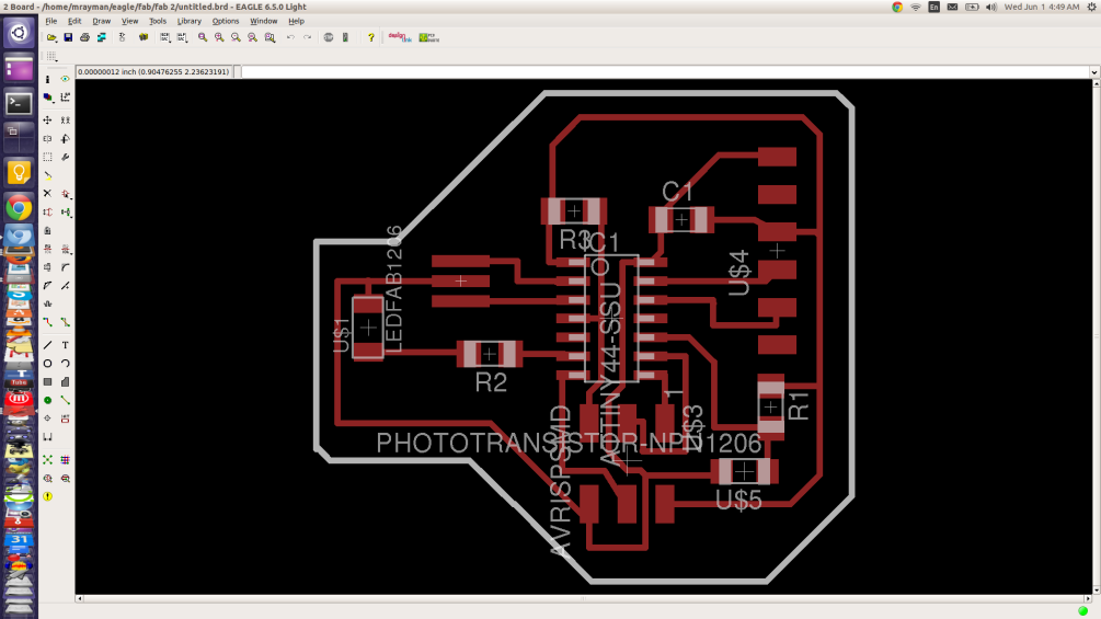
Step 2: Circuit Design
I came very comfortable using Eagle to design the circuit. I used the same design for used for the Electronics Design assignment, and start editting it.
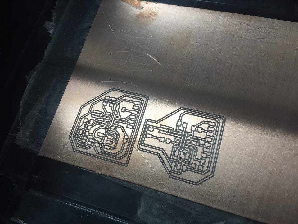
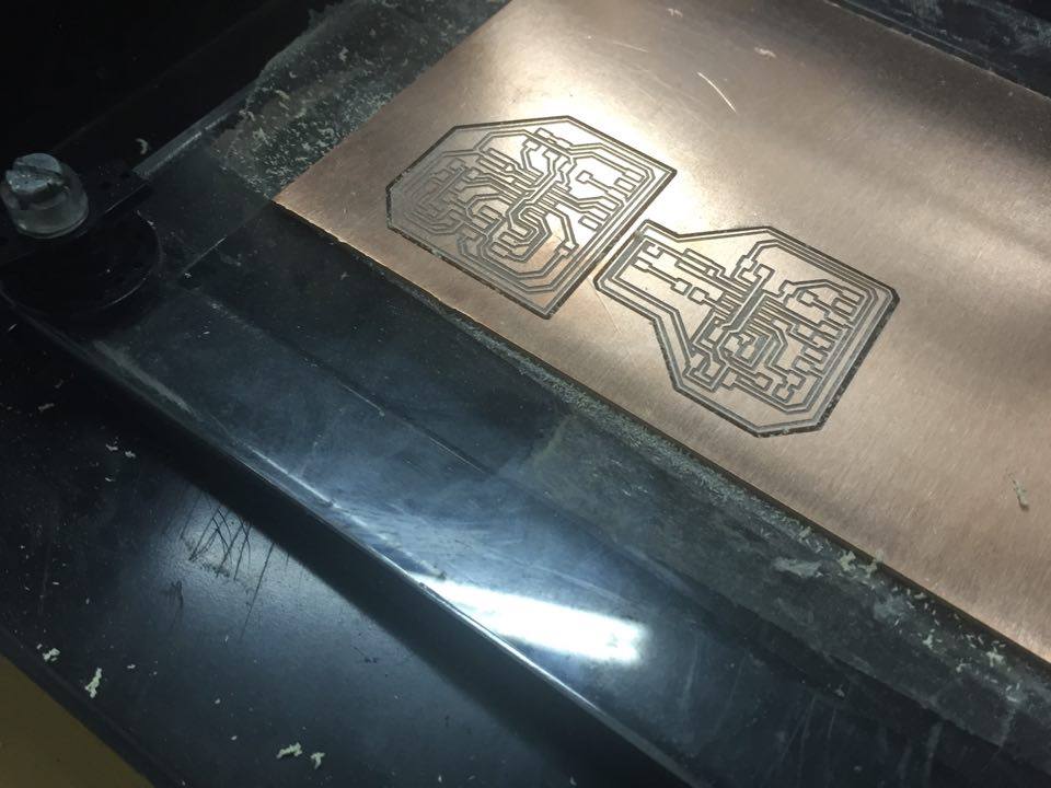
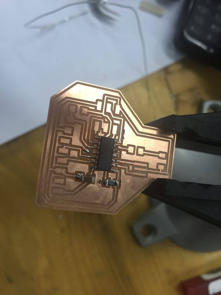
Step 3: Milling the board
Up to this point, I have used the Roland Modela MDX-20, to make over 10 circuits. This time I took the image of the cirucit and added it to the image of my friend's circuit to save time and material.
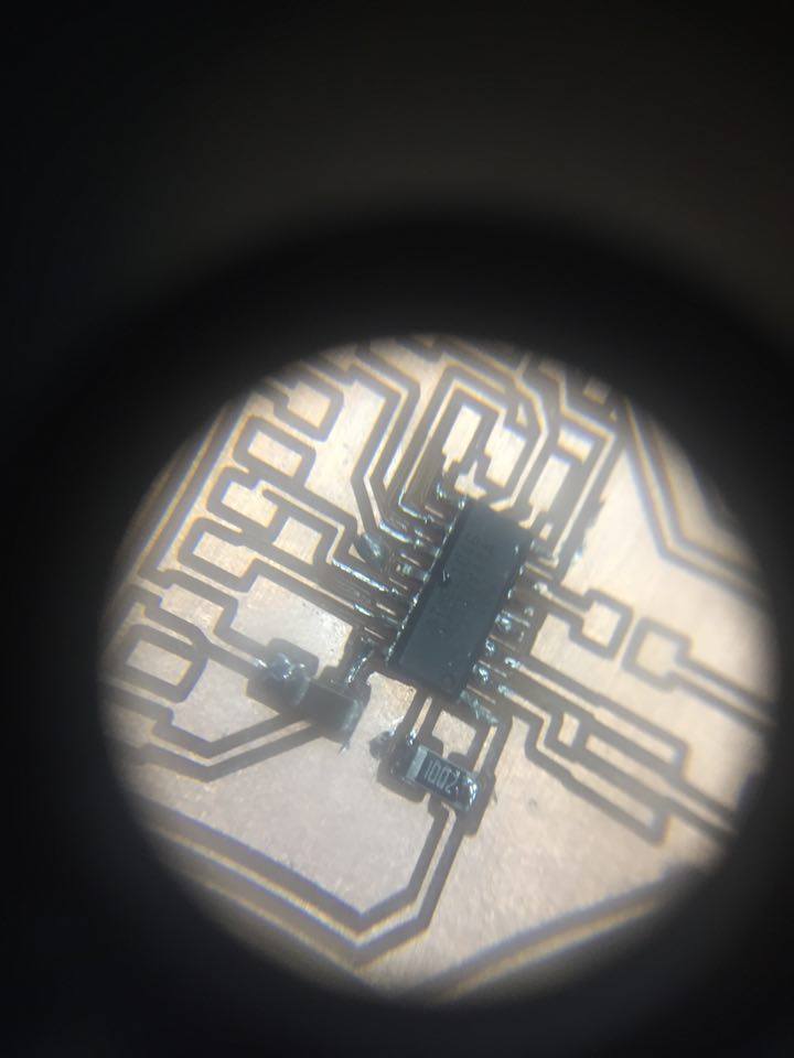
Step 4: Soldering the board
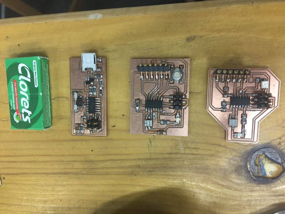
Practice makes perfect. The more you try, the better you get.
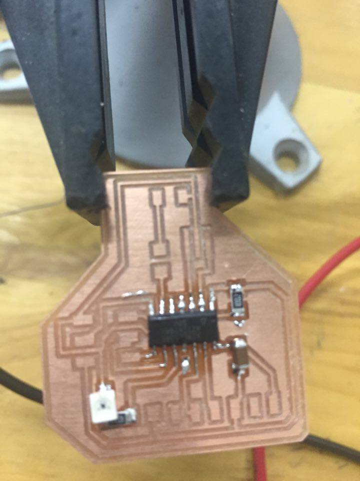
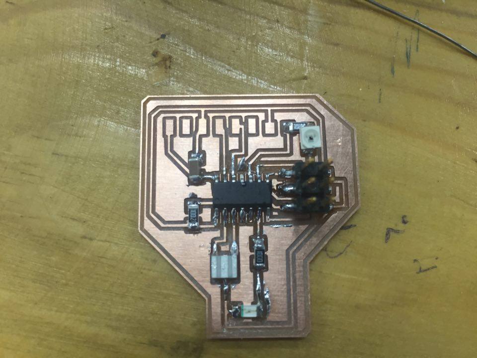
This is my collection so far.
Step 4: Programming the Board
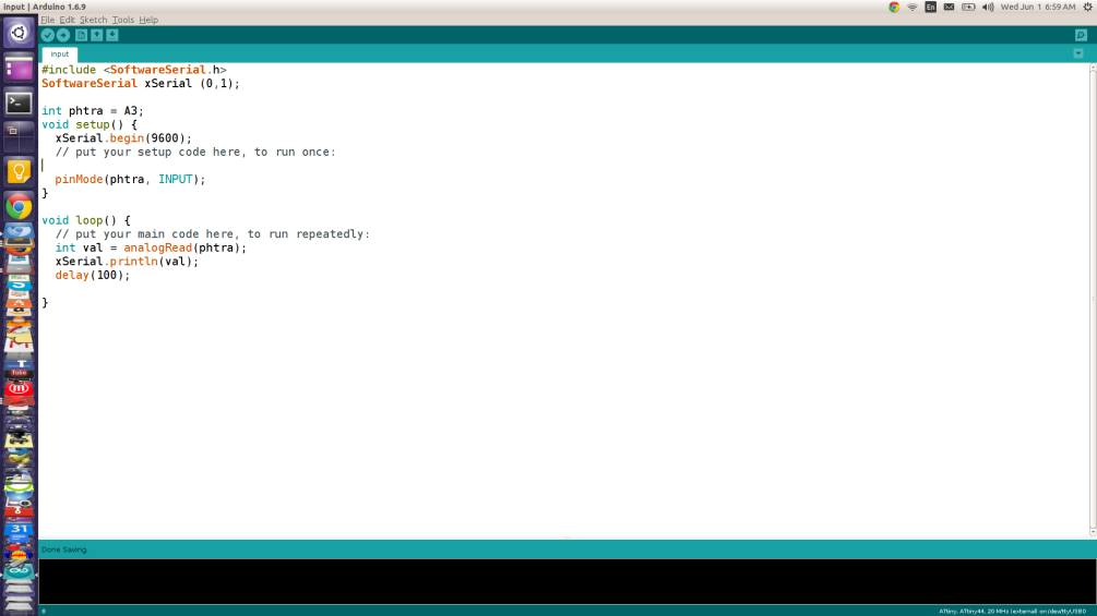
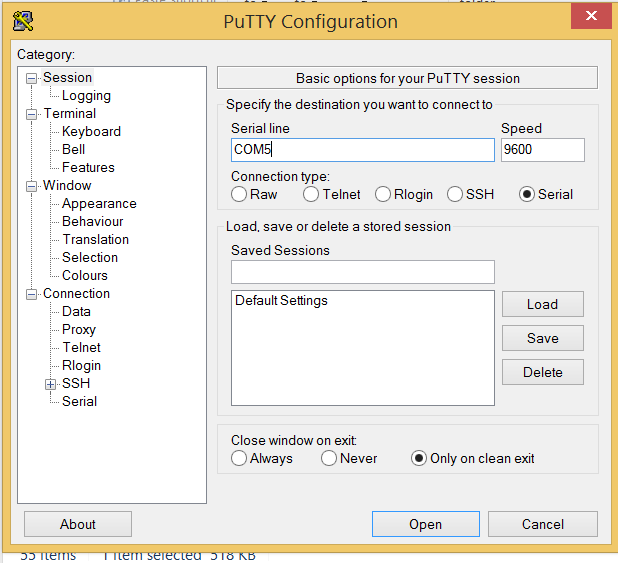
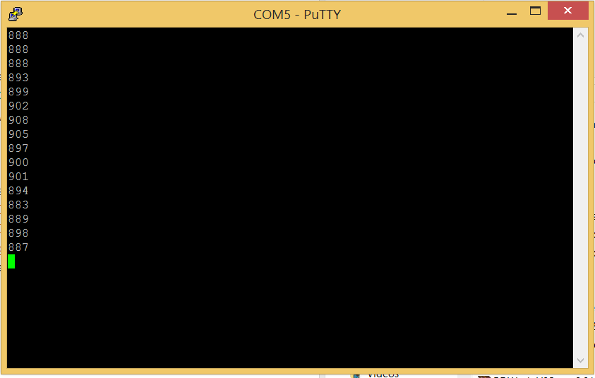
As I said at the beginning, this board combines the input and output. I have implemented a test code to show how we read the data from the sensor. I'm using Arduino IDE on windows, because my Ubuntu had a bug and can't recognize the FabISP anymore. To screen the data from the serial ports, you will need to install FTDI drivers from here., and you can use any serial emulator likea here., or use arduino embedded serial monitor.