Mechanical Design
This week assignment is a group assignment to do the following tasks:
- Make a machine.
- Include the end effector.
- Build passive parts.
- Operate it manually.
Step1: The Idea
- We gathered as a team and brain stormed many ideas and finally we chose to make a farmbot that can plant seeds and water them.
- We separated into two groups a group working on the machine mechanism and a group working on the end effector design.
- I were in the group working on the machine mechanism with Assem and Haggag.
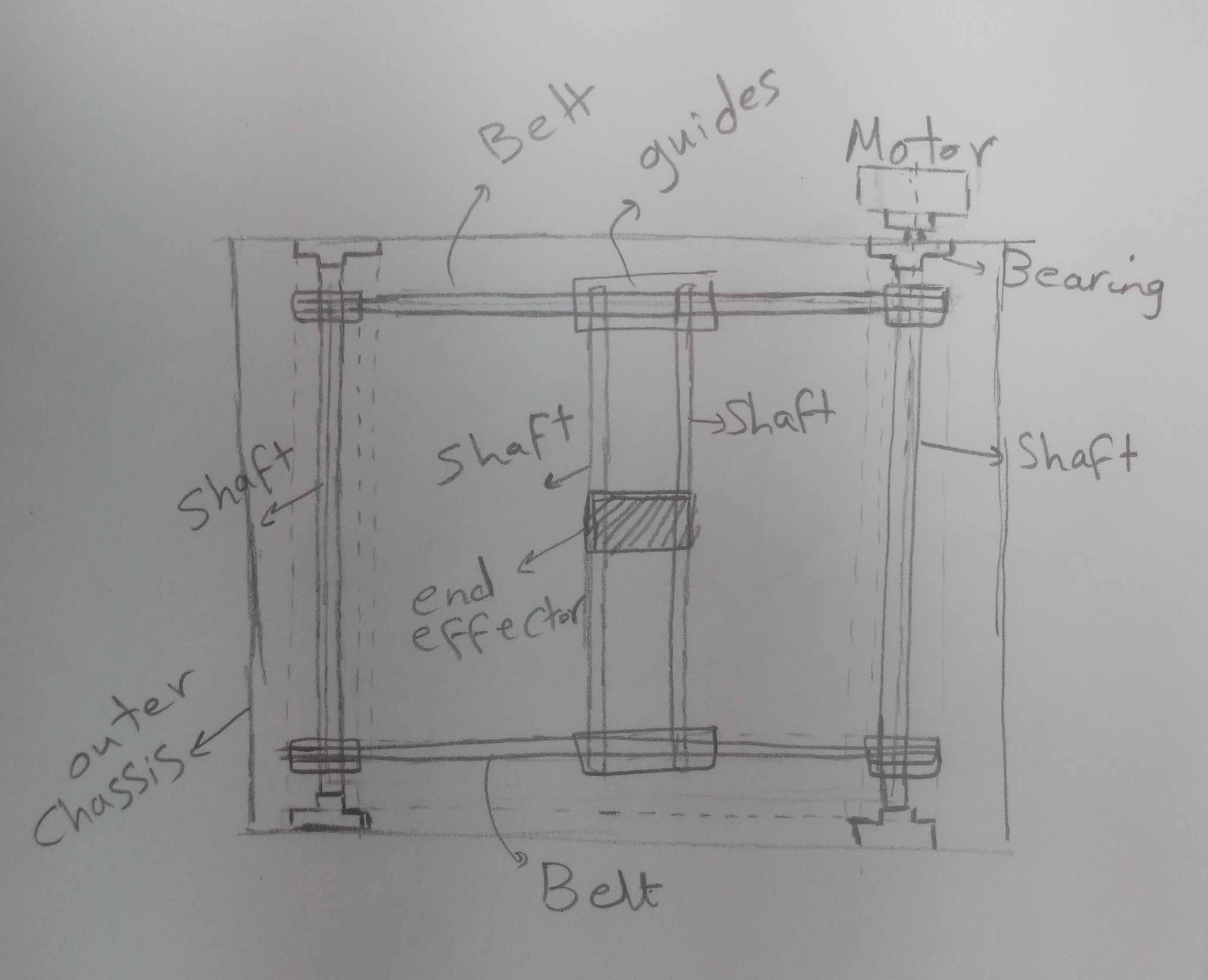
Step2: Mechanism Design
After brain storming and checking some open source farm bots like Gensis we decided the following:
- The machine outer dimensions area will be 50*50*50.
- The mechanism will be in XY only and no motion in the Z axis.
- The main components that we will use are bearings, belts, Shafts, motors and wood sheets.
Step3: Learning new things
I’m not very good in Mechanical design so Assem and Haggag teached me a lot of information
- Grab Cad: It’s a website on which we can find free and open source Cad models for assembly and for editing. For example if I want a bearing for my machine mechanism assembly I don’t have to draw it but I can get it from Grab Cad. The files are available in different extensions like STEP which is used in assembly or different CAD programs extensions like solid works, fusion 360,…. The Grab cad also offers some services like GRABCAD print and GRABCAD workbench.
- CNC joinery notebook: It’s an article published on Makezine website that is very useful to know about different types of joints, when you can use it and the advantages of each joint type. This was a very interesting part to me.
- Bearing: I became familiar with bearing which I never used before. It’s an element which constrains relative motion to only the desired motion, and reduces friction between parts “This definition is from Wikipedia”. I also knew two types of it Roller bearing for circular motion and linear bearing for linear motion.
- Fusion 360 : I learned new functions like how to create new plans and work on it, how to actually use parametric modeling and some tricks I discovered by practicing.
Tutorials I watched:
- https://www.youtube.com/watch?v=tePXb99metE
- https://www.youtube.com/watch?v=h7L7lo2nsY8
Step4: My contribution
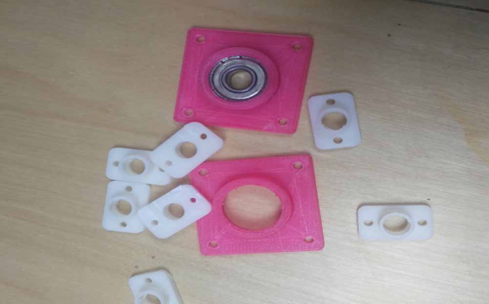
My contribution in our group assignment was to design a bearing and a shaft housing to be able to mount them in the chassis and laser cutting the machine chassis.
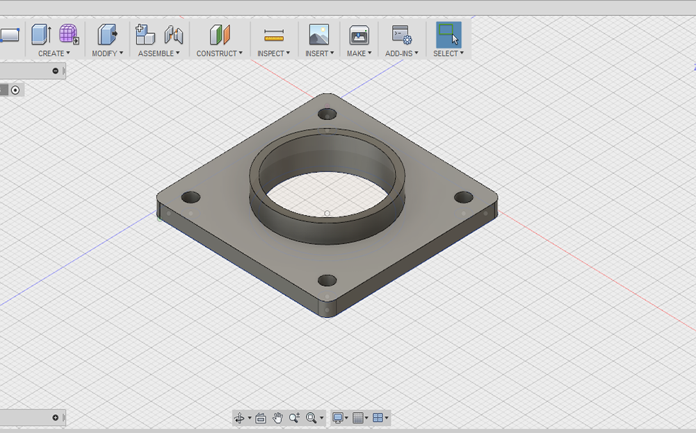
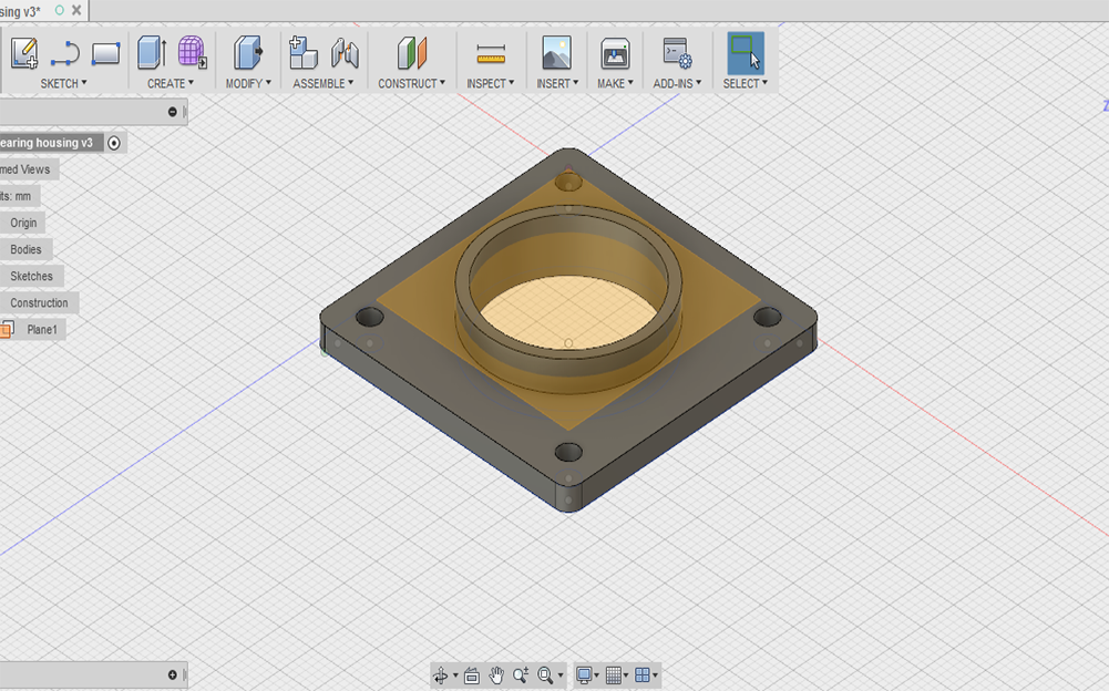
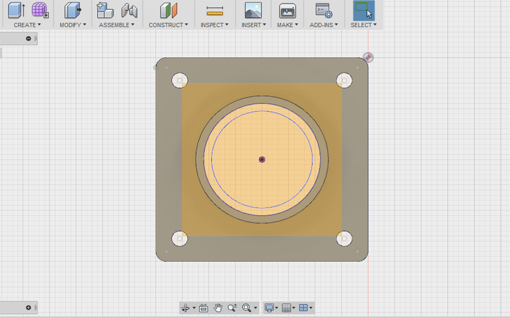
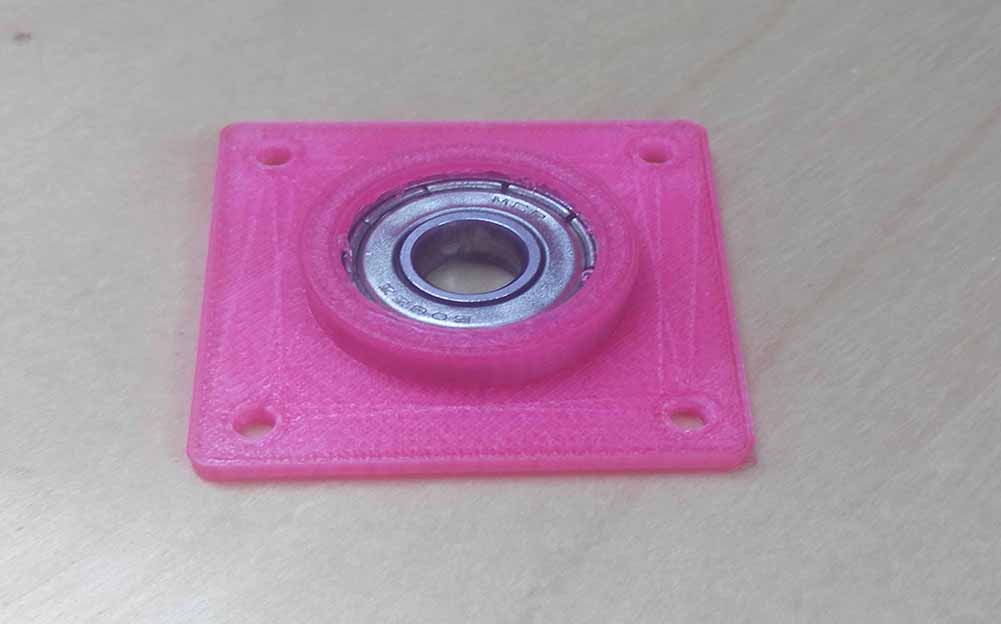
- Bearing Housing
- Knowing the dimensions
- Quick hand sketch
- Designing
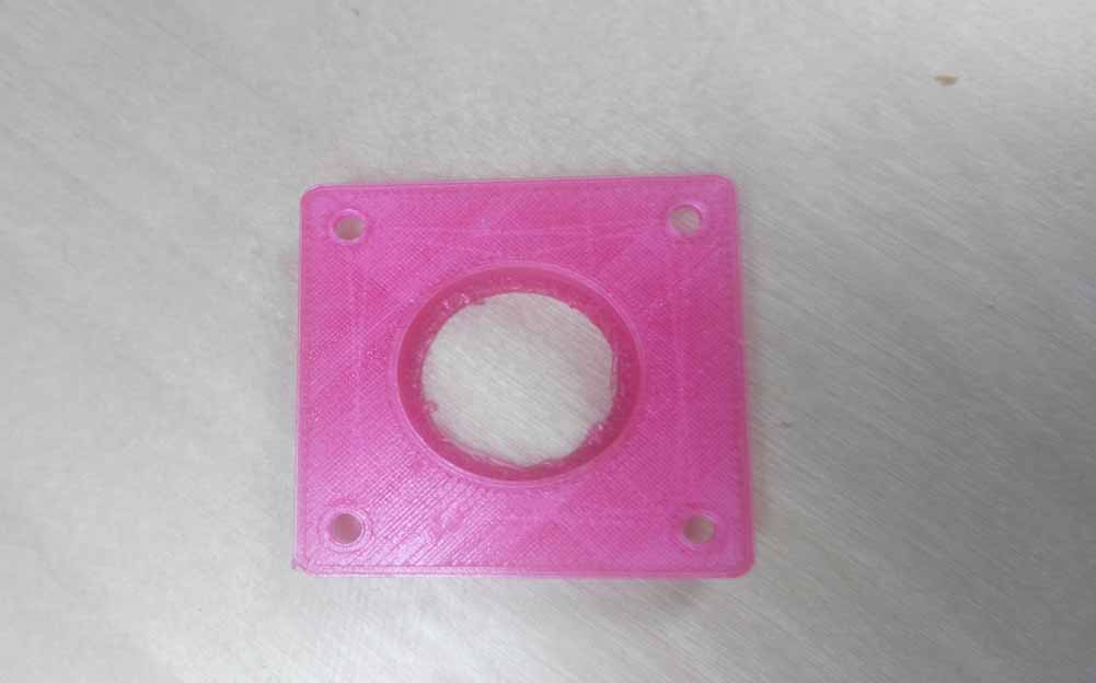
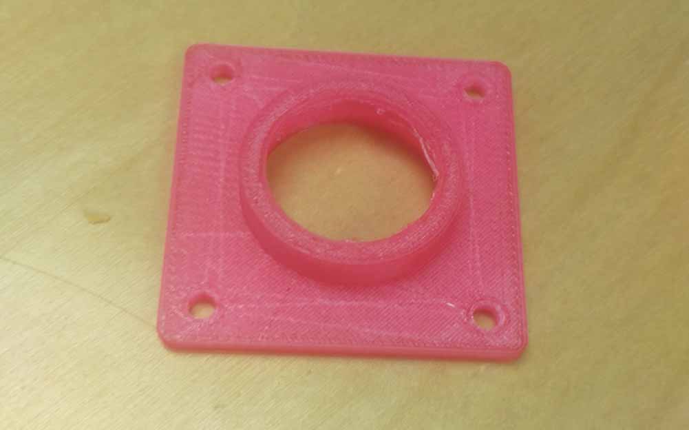
- 3D printing
- Shaft housing
- Laser cutting
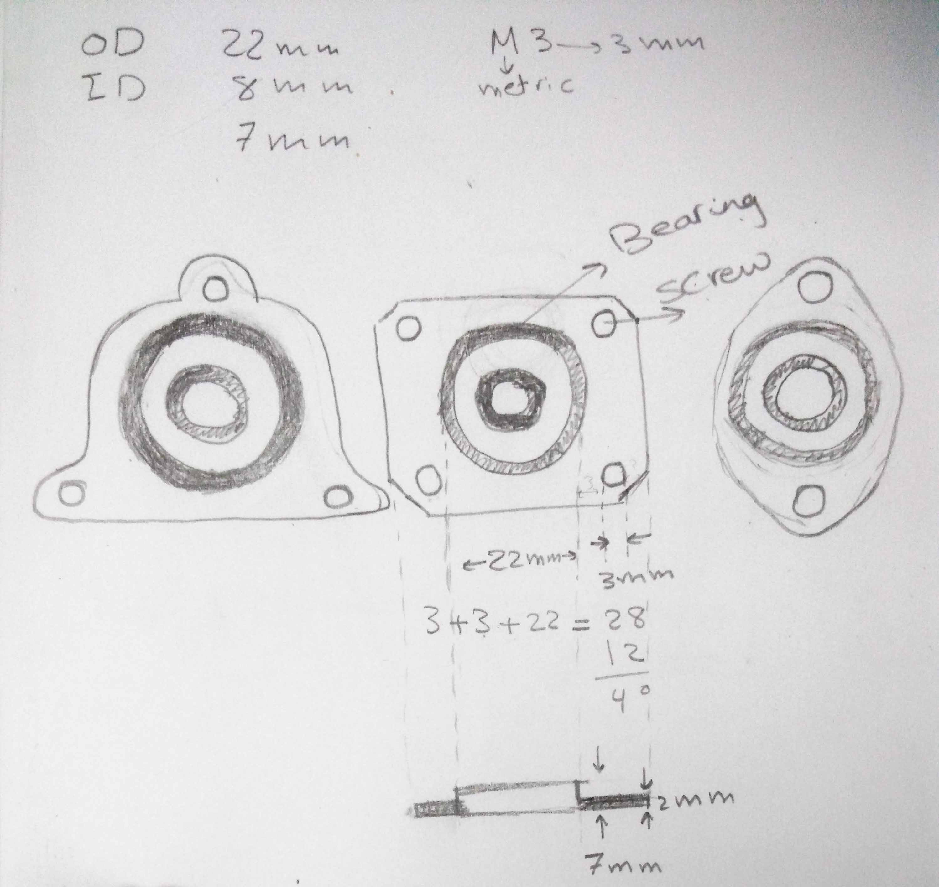
I started to know the dimensions of the bearing and screw that we are going to use through the vendors sites
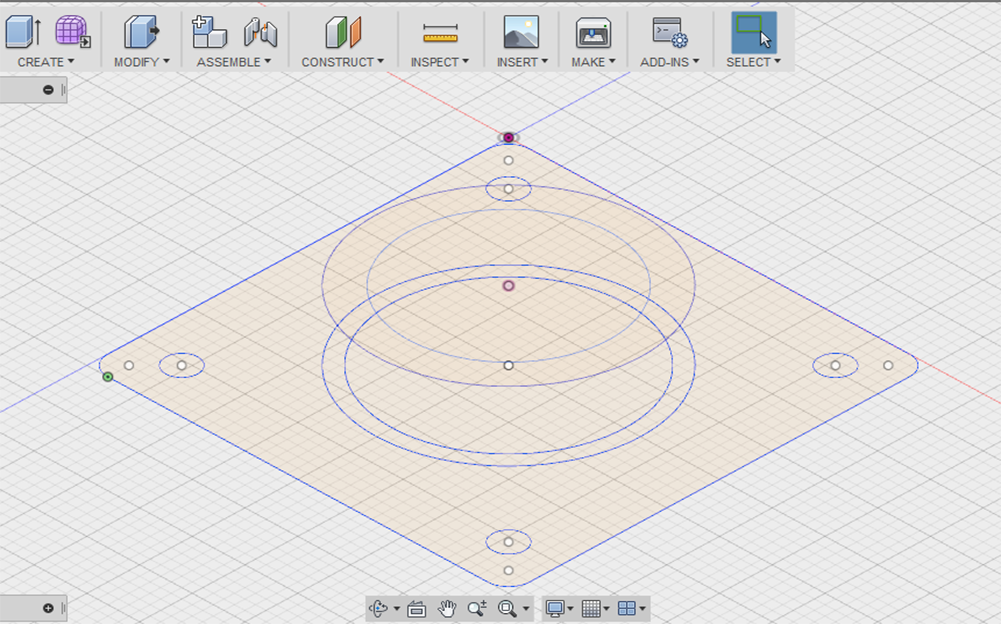
For the Bearing: Bore: 8mm - Outer D: 22mm -Width: 7mm / For the screw: +3x16 mmAfter navigating thingvirse site for ideas about bearing housing I started to make a quick hand sketch for the housing I was going to make. I draw three different Ideas
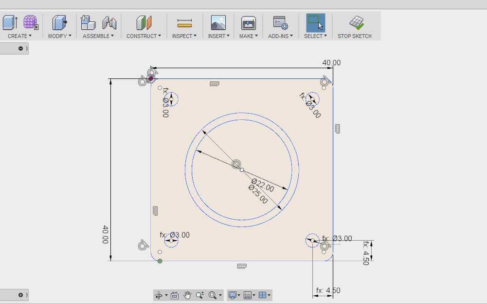
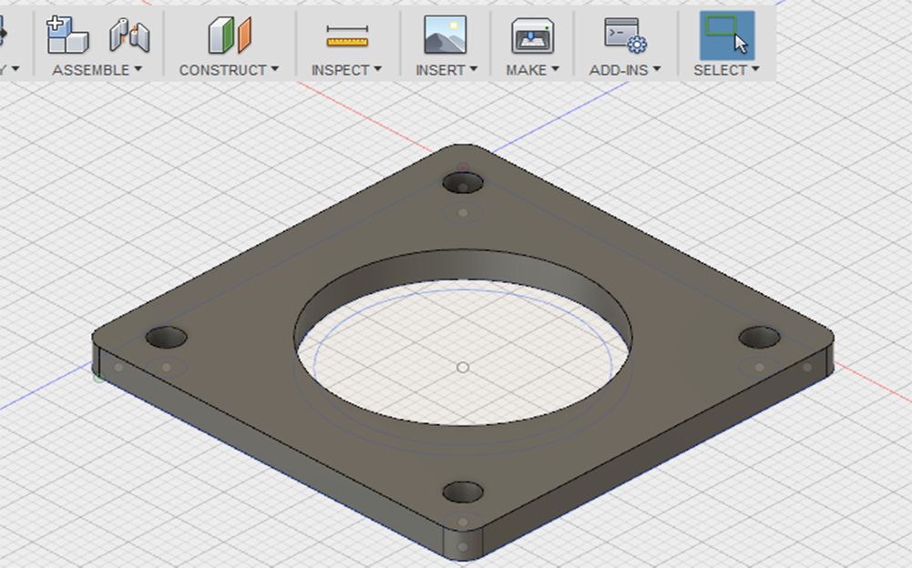
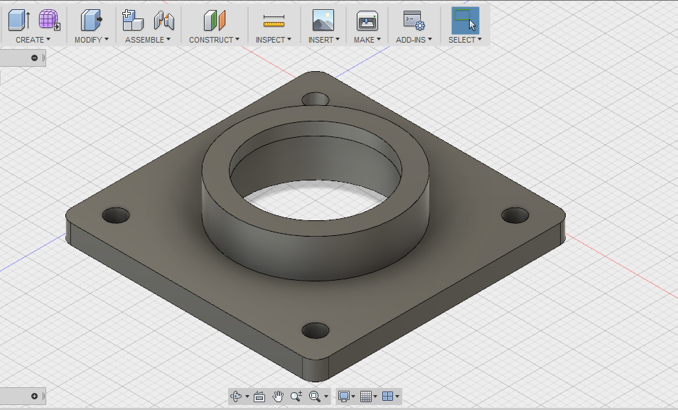
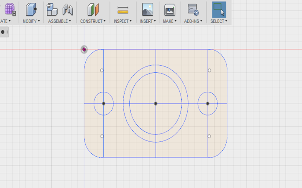
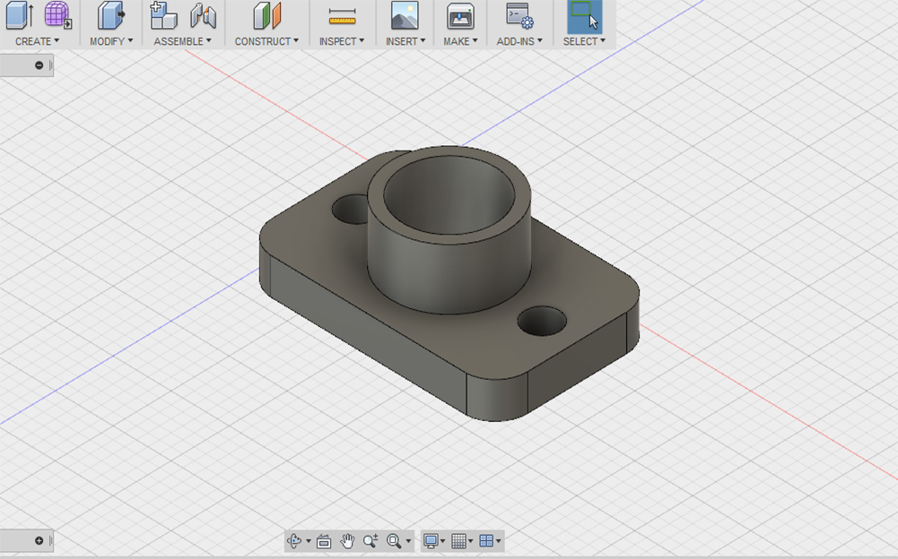
I used Fusion 360 for Desigining and I used these functions : Sketch, Extrude, Parametric, modify, Timeline and Plan to draw the housing and make a narrower circle on the top to prevent the bearing from getting put while moving.
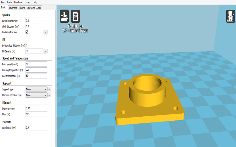
I used The Maker space at EBNI IoT incubator for this week tasks. The 3D printer at EBNI was Wanhao Duplicator i3 plus 3D printer.
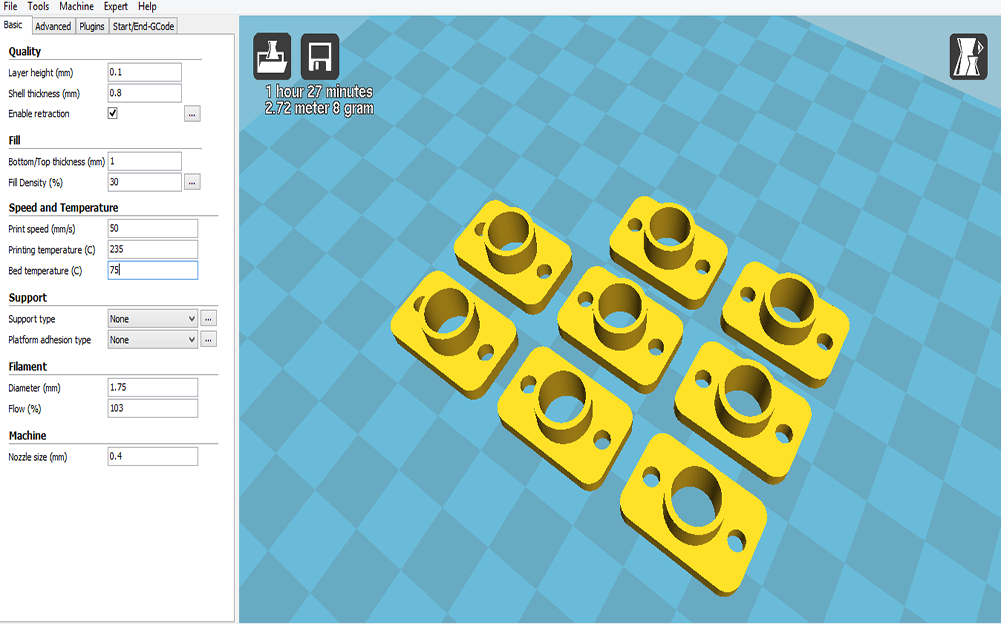
I used Cura to adjust the 3D printing settings. it took 43 minutes and 5 gms for each part
I followed the same steps I did in the bearing housing, Sketching, Designing and printing. The dimensions were smaller so It took only 1 hour 27 minutes and 8 gms for 8 parts
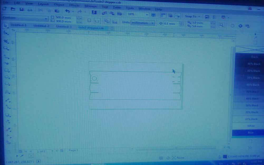
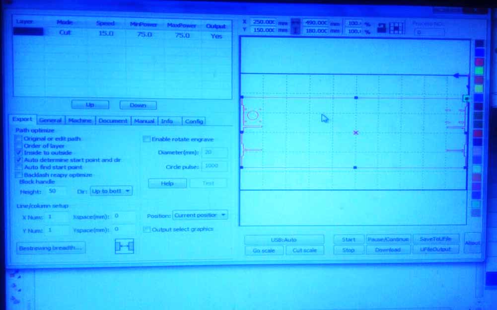
I took the dxf extension of the designs made by assem then opened them with Coral Draw for checking the dimensions and if we need any modifications.After that I exported them to the laser cutter software and adjusted a power of 75 and a speed of 15 and Finally cutting
Design Files
My contribution in our group assignment was to design a bearing and a shaft housing to be able to mount them in the chassis and laser cutting the machine chassis.
That's all for this week :)