- Week 7 +
computer-controlled machining
Tasks
Concept
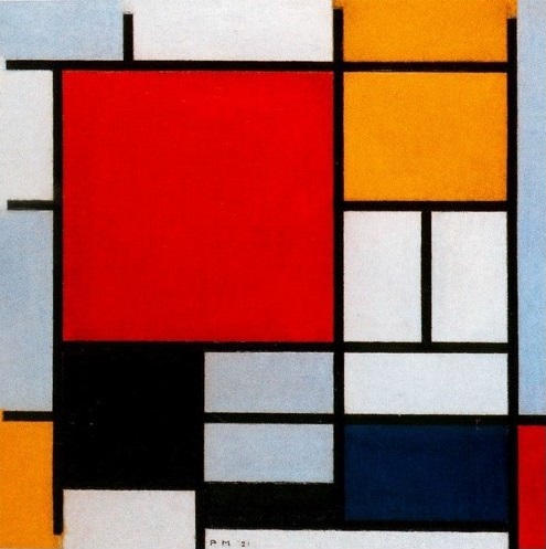
To start with this week's exercise, I thought of picking up a piece of art to take inspiration from, and design something big out of it. Early 20th century art movement De Stijl has always fasinated me immensely. I have always believed that the this art movement has great potential that is yet to be realised. It died way too early than it should have. I looked at the works of De Stijl artist Piet Mondrian for some stimulus. The neoplastic nature of his masterpiece "Composition with Large Red Plane, Yellow, Black, Gray, and Blue, 1921" instigated an idea of recreating it's composition for a purpose. Art for Art is what I am calling my final object of this week. I will be making a storage rack for artists. It seems to be a good choice to bring conceived idea to reality.
Design Development
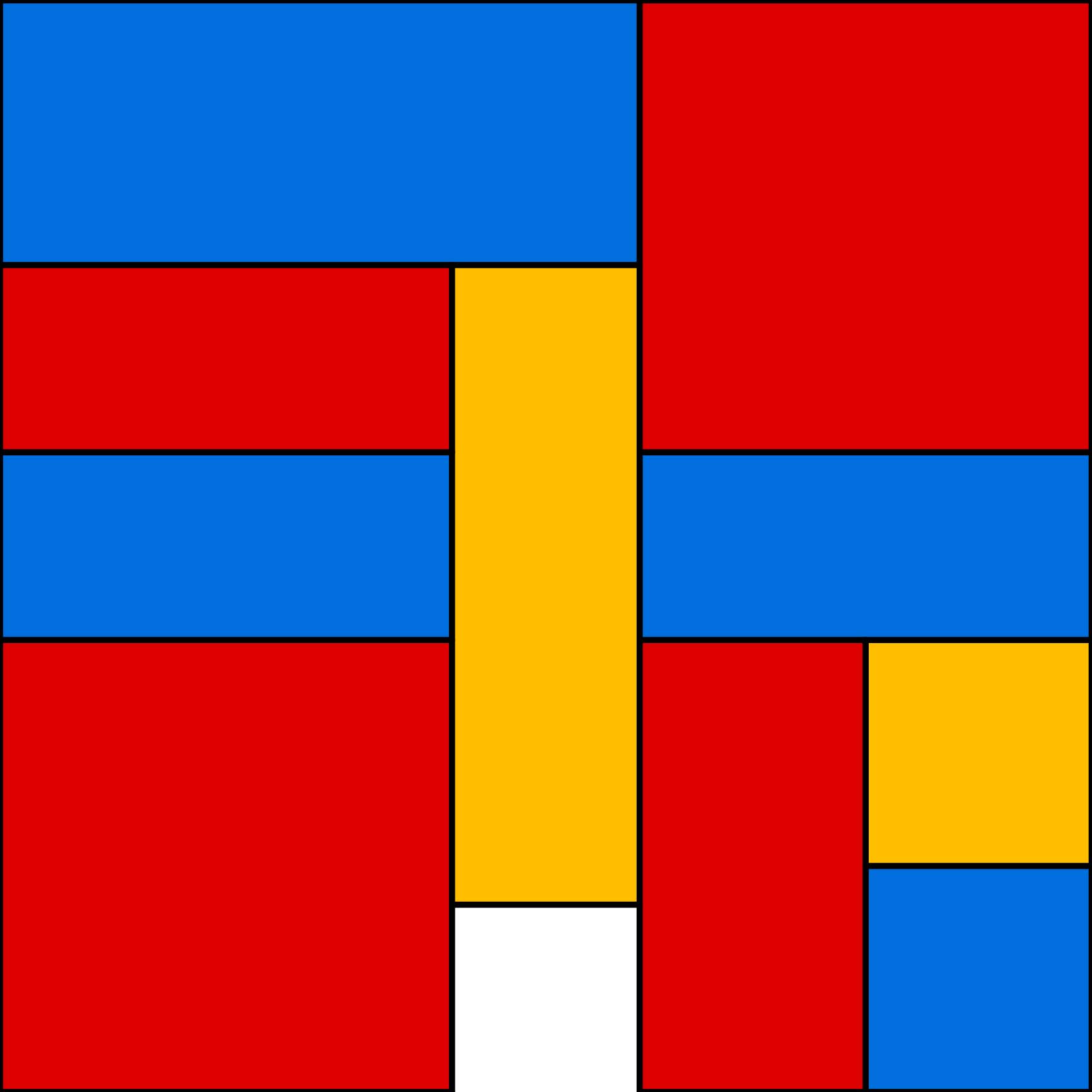
Firstly, it is important to understand the composition in the art work and recreate it.
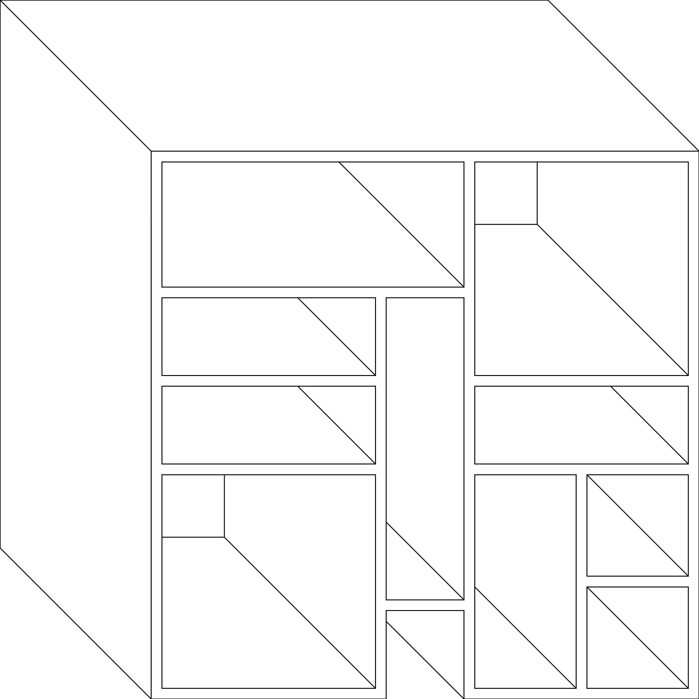
My next response is to give three dimensionality to the black grid lines by simply extruding the them.
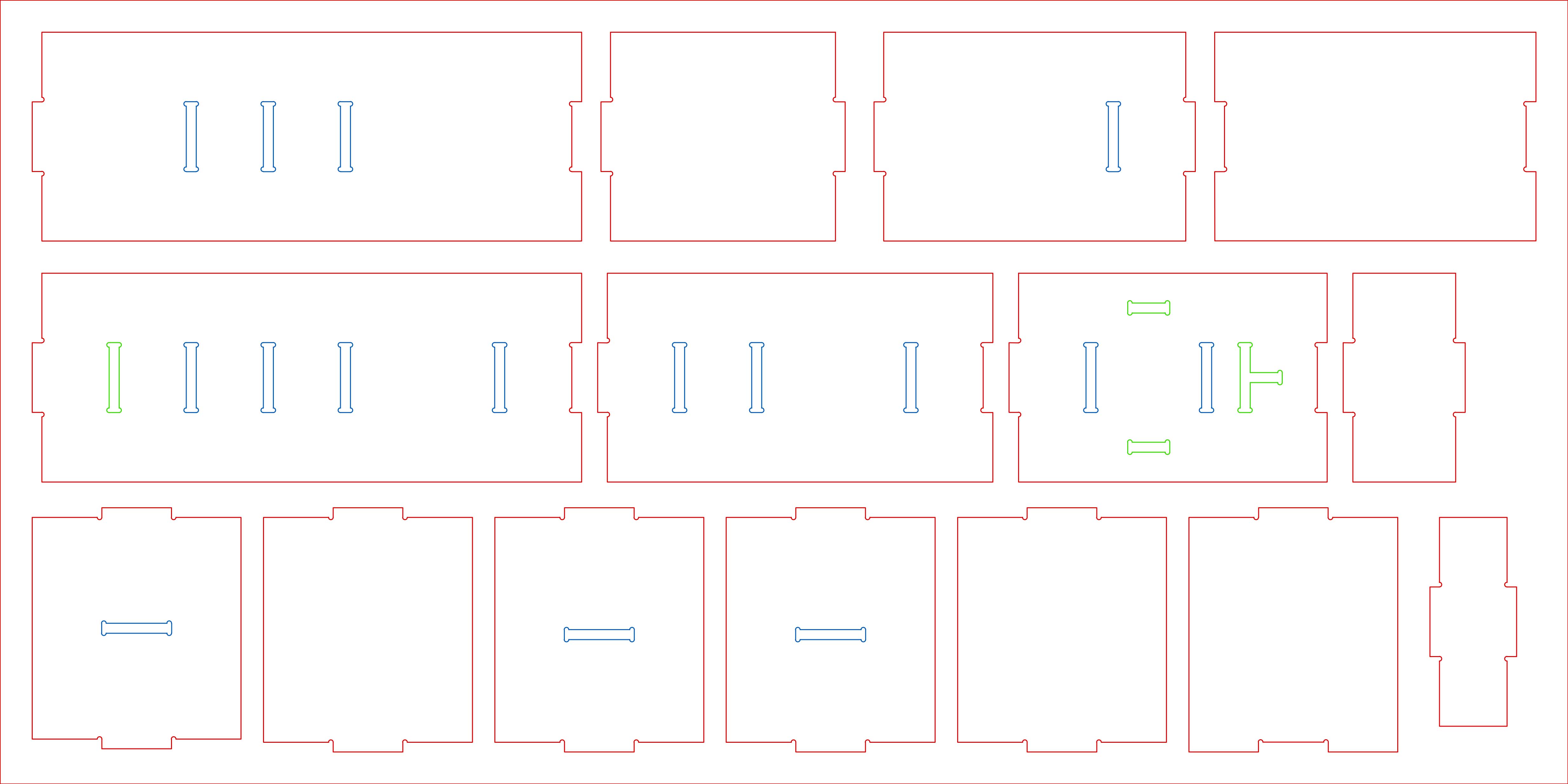
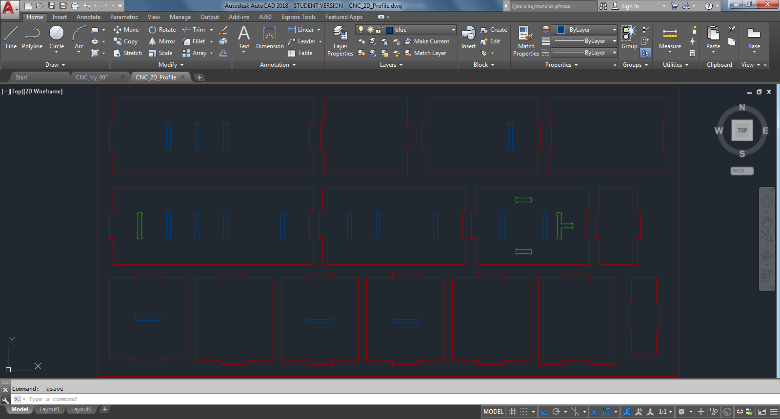
Then I created 2D profiles of all the components including dogbone joinery. The way I have design the storage rack eliminates the need for glue or screw. Nesting - since the idea is to use only one board and minimize the raw material waste, my design fits within a board. In the following drawing, red lines are for outside cuts, blue lines are for inside cuts and lines in green are also for inside cut, but are for future extensions to the final object, which are not going to be utlised in the building of final object for this week. The drawings are made in Autocad, a screenshot has been provided below.
Creating toolpath for Machining
After a brief research, I learned that “Toolpath”is a CAD/CAM related term that is basically a series of coordinate locations that a cutting tool will follow in the machining process. Toolpath is traditionally divided into two categories: Roughing and Finishing. A roughing toolpath is generally used in the CAD/CAM cnc programming phase for removing the most amount of material possible, as accurately and as efficiently as possible. Finishing toolpath comes after roughing and essentially “finishes” the cutting process removing the last amount of material on the machine to complete the machining process.
Since I am have to cut only 2D profiles, I need not to create roughing and finishing toolpath which are required for 3D milling. Following screenshots demonstrates the process of creating toolpath in PartWorks.
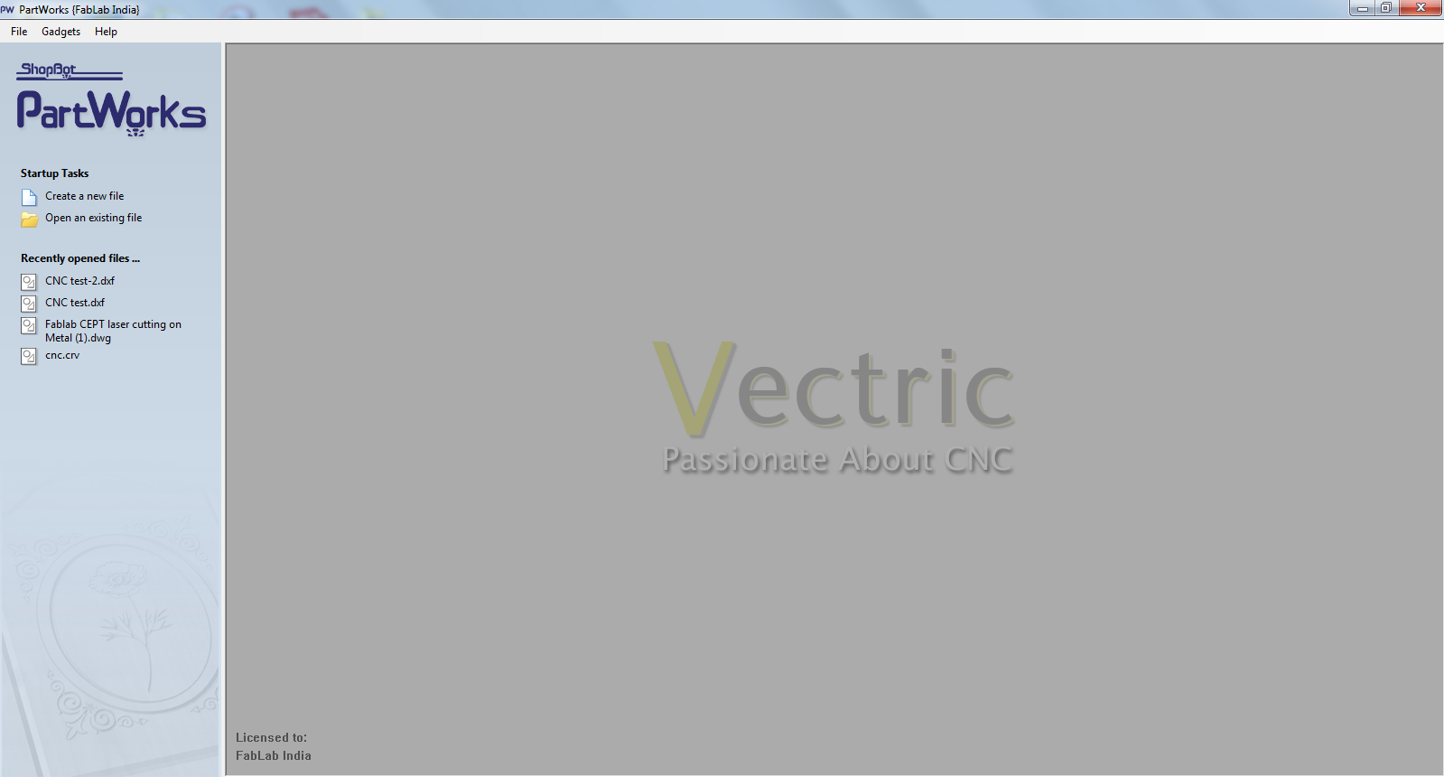
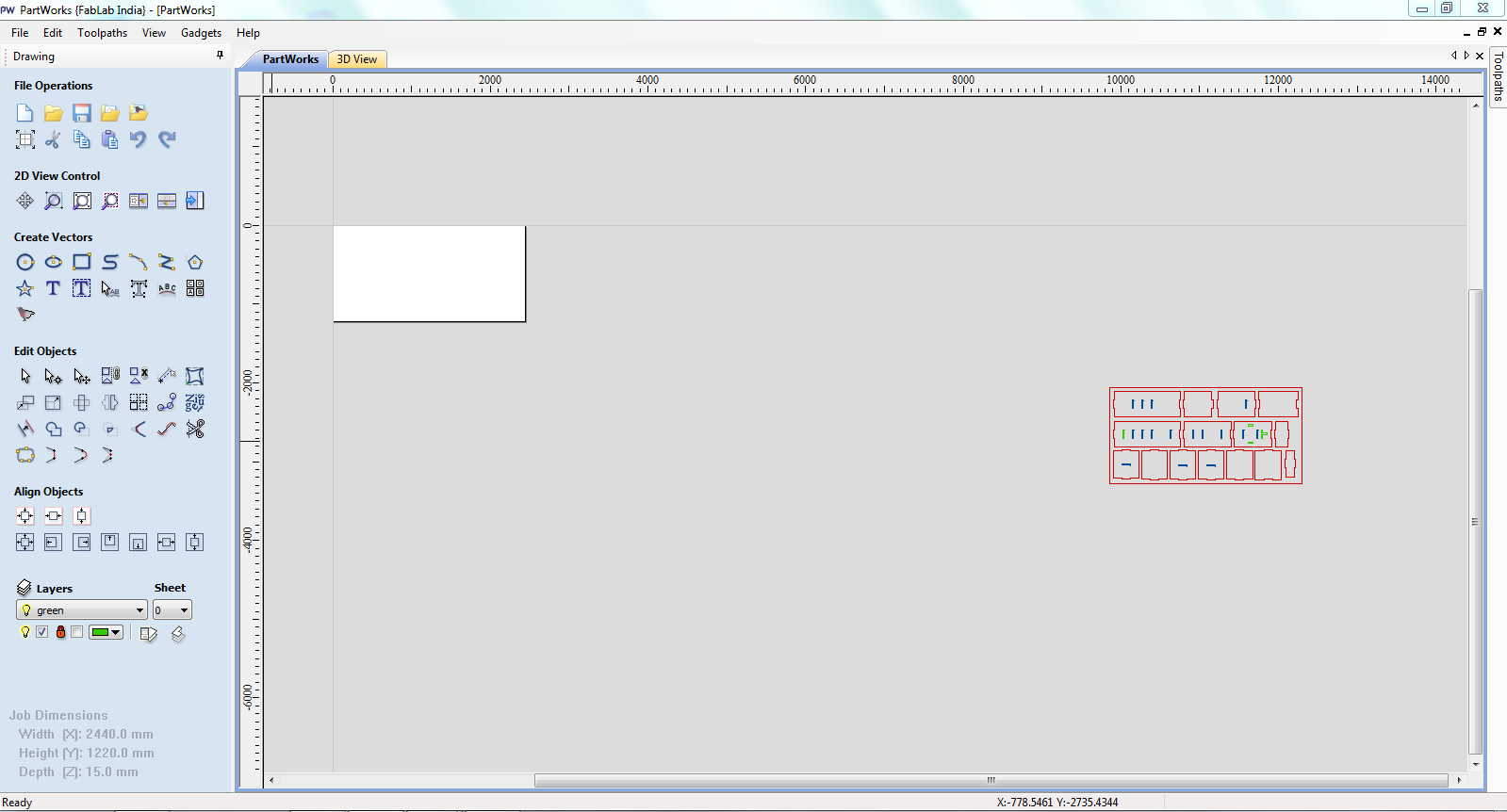
Firstly, I exported .dwg file to .dxf file and then opened in Partworks 2D to create machine code for milling. Upon opening the software, below screen appears giving an options for startup tasks.
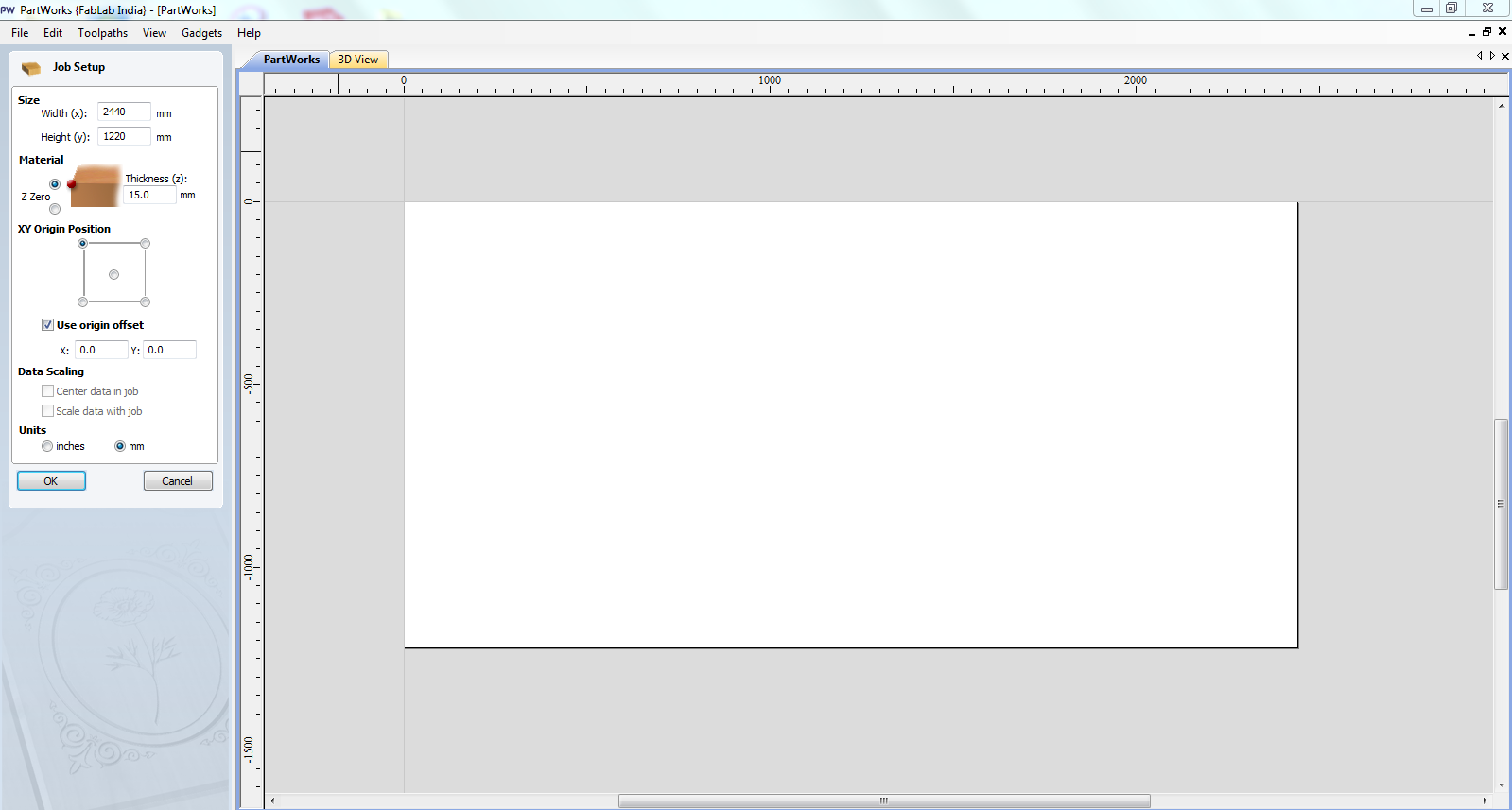
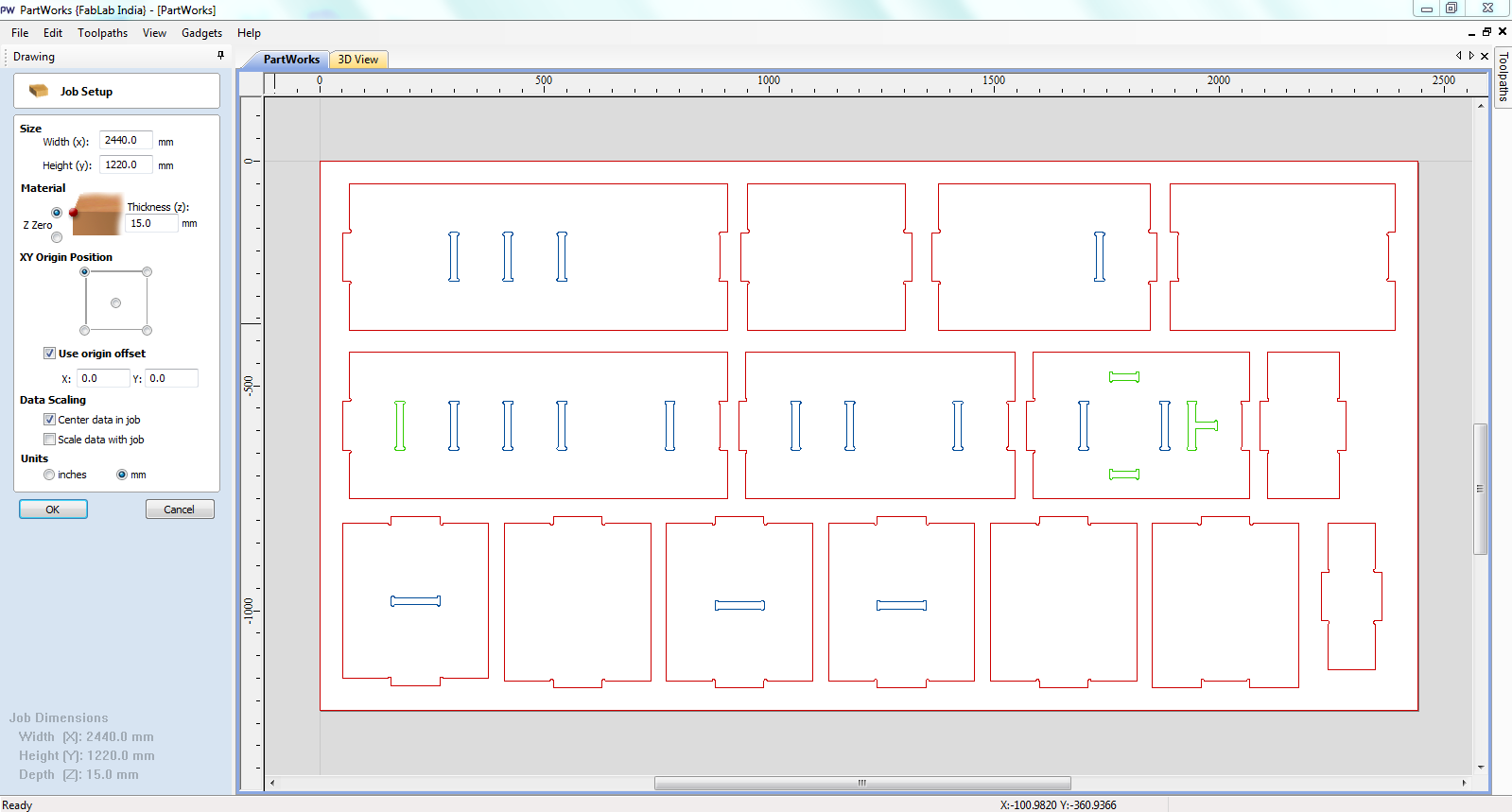
The next step is to do job setup: Bedsize as 1220 x 2440mm, material thickness as 15mm along with selecting XY origin position.
Then I imported the file in the workspace, and it appeared to be outside of the set work bedsize.
I brought the data in center of the job by going back into the job setup.
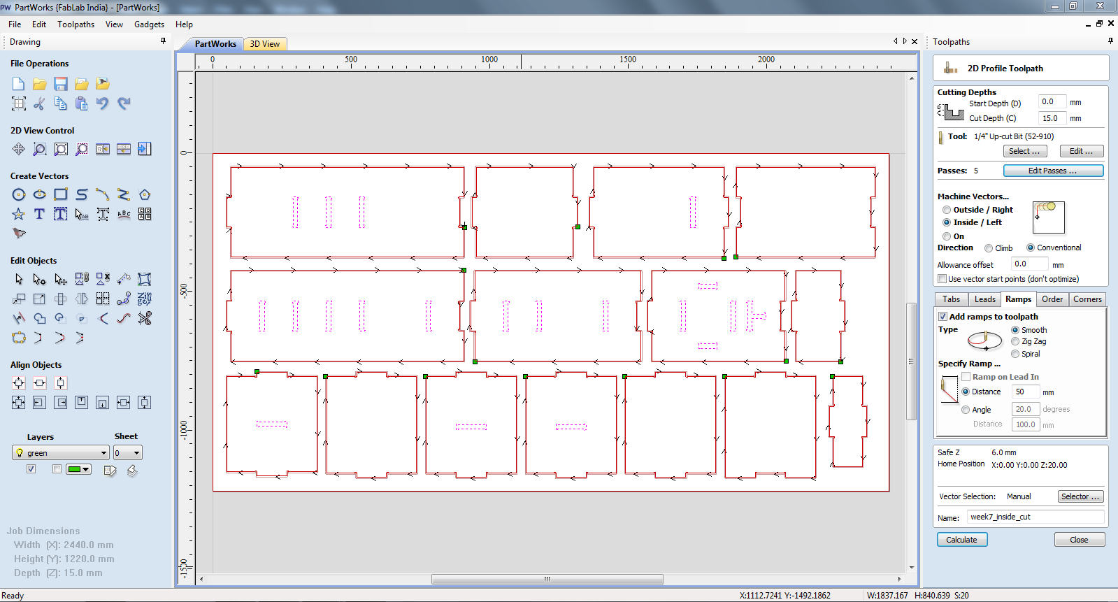
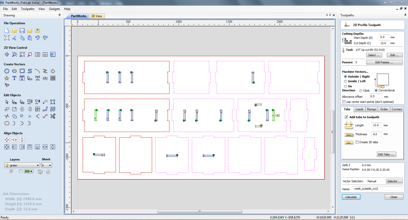
Next, I had to setup the parameters for both inside and outside milling. The settings and the tools I used are:
1/4th" Up-cut bit, End Mill tool type, 6000 r.p.m Spindle speed and Feed Rate and Plunge Rate as 0.5 inches/sec.
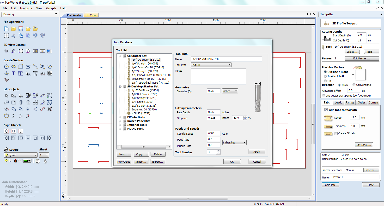
Number of passes I kept were 5 with 12 mm long and 4 mm thick tabs.
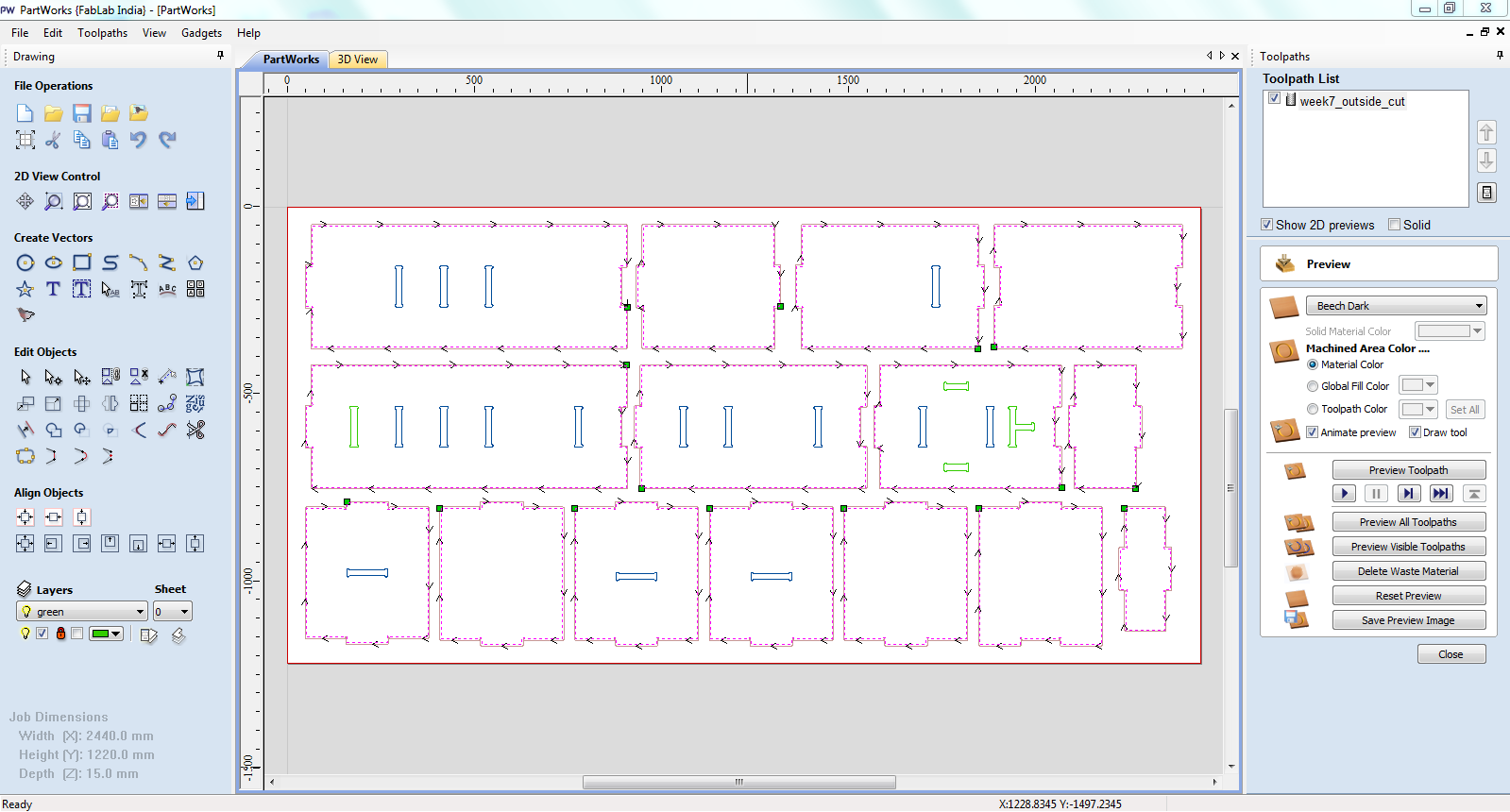
After creating toolpath for outside milling job, I created similar toolpath for inside cut by changing machine vectors.
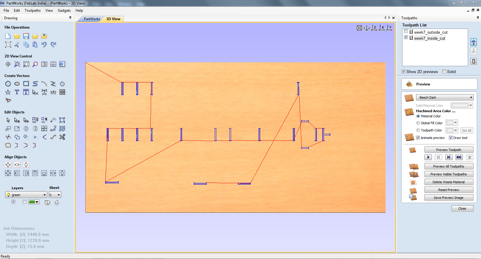
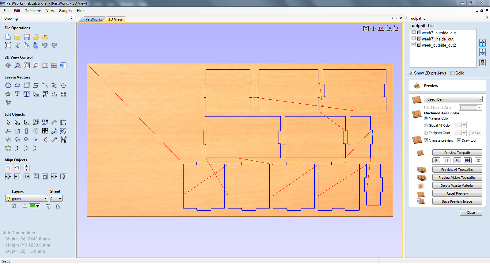
Following is the preview of the inside milling toolpath. The next step is to save both the toolpaths.
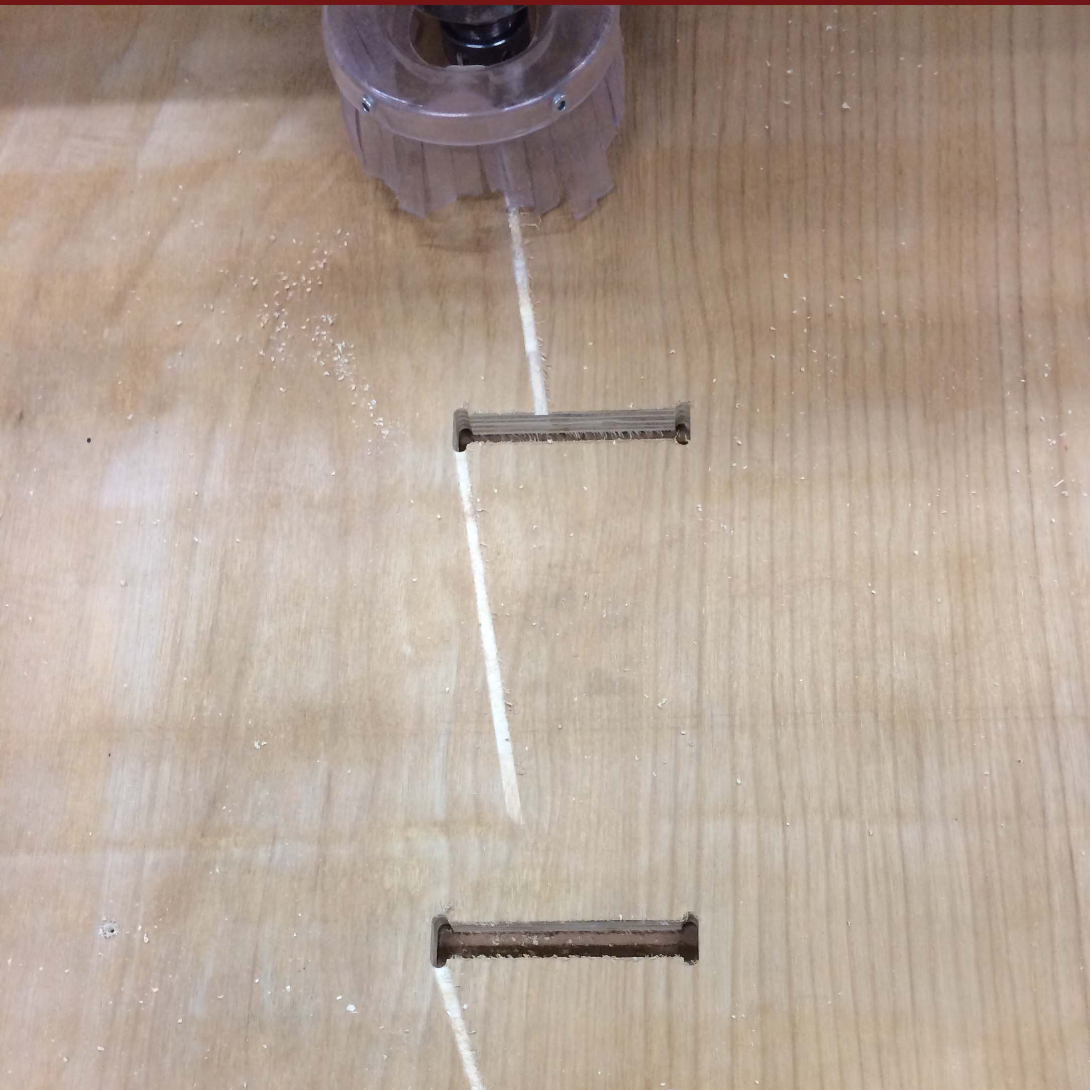
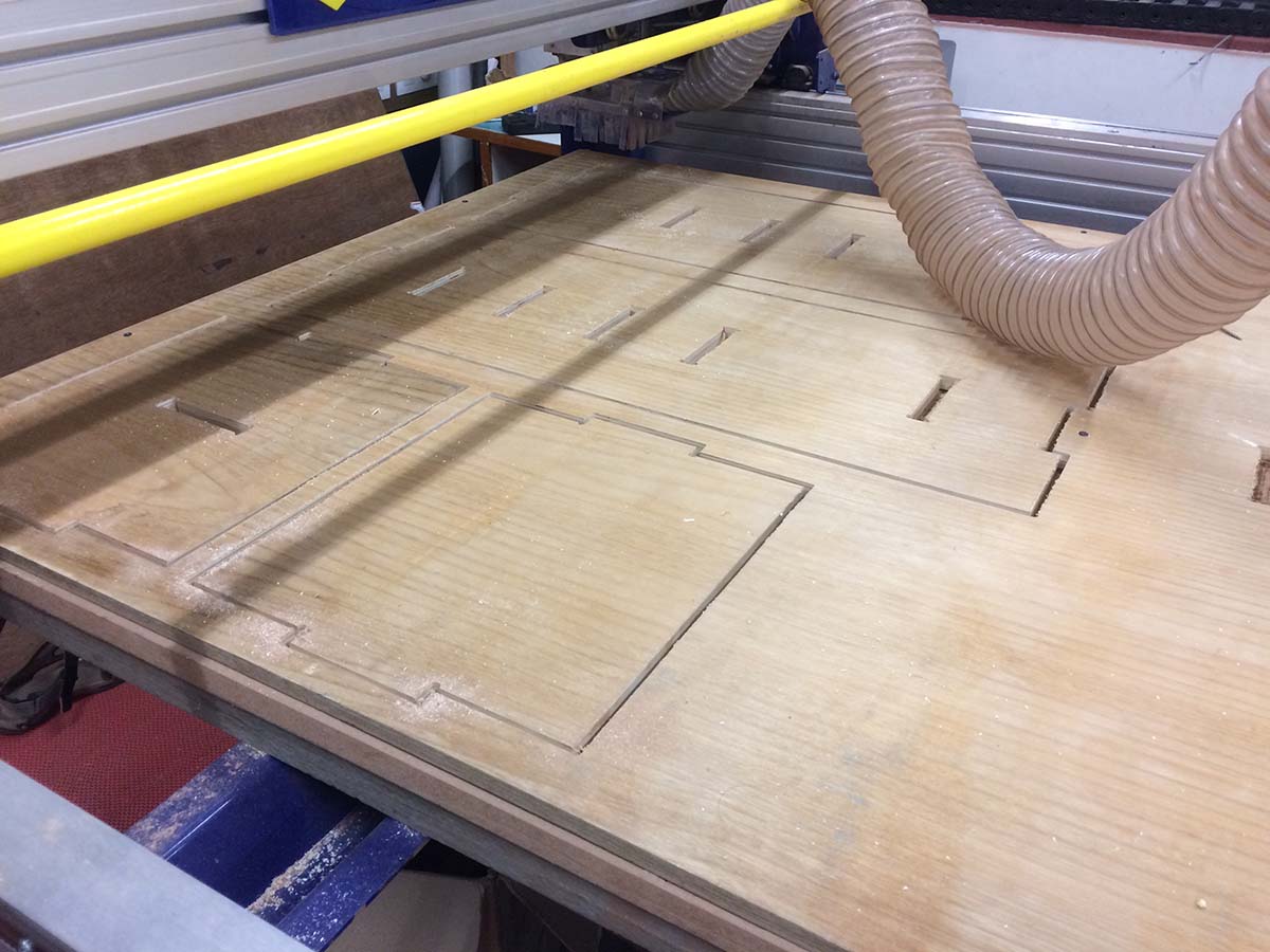
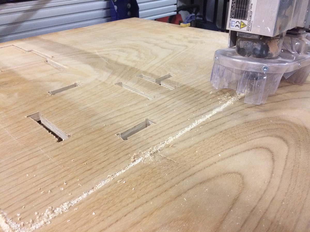
The only shortcoming that I faced was due to slight bend in the milling board. Because of this the spindle had created following marks while moving from one point to the other after finishing the job. The fix was actually very simple I just had to change the Rapid Z Gaps above material from 6mm to 18mm.
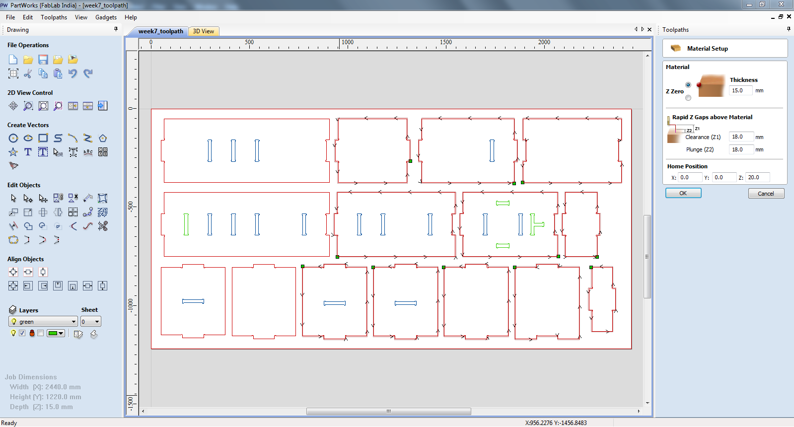
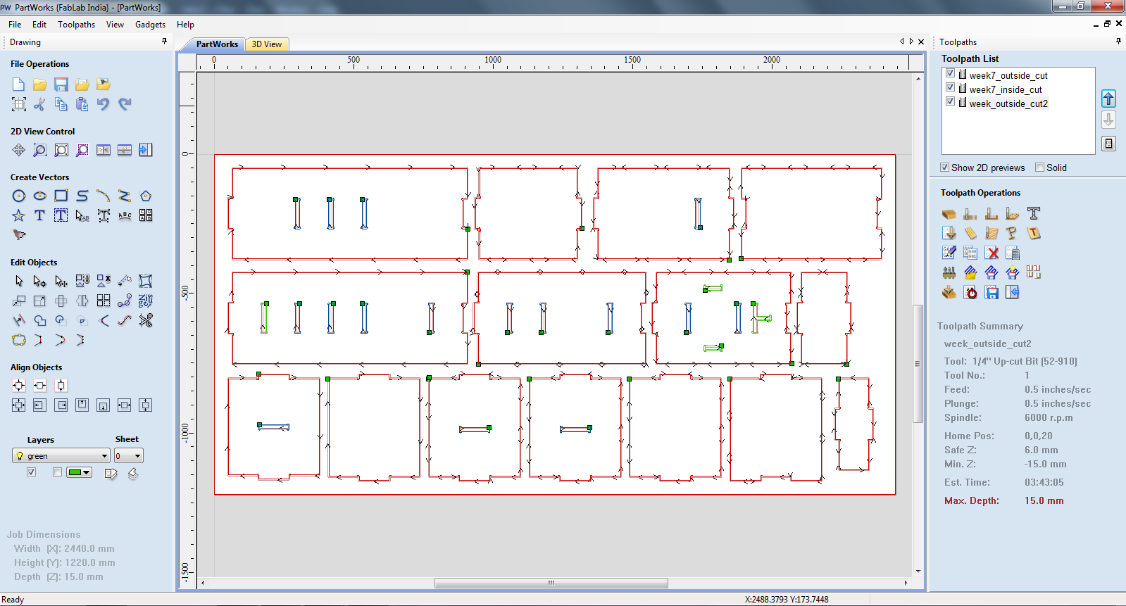
Before resuming the milling process, I created another toolpath of the remaining parts which I could not mill as I had to stop the process inbetween.
Finally, all the toolpath could be seen in the toolpath list.
Machine Setup
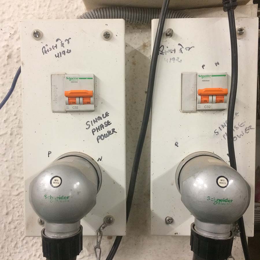
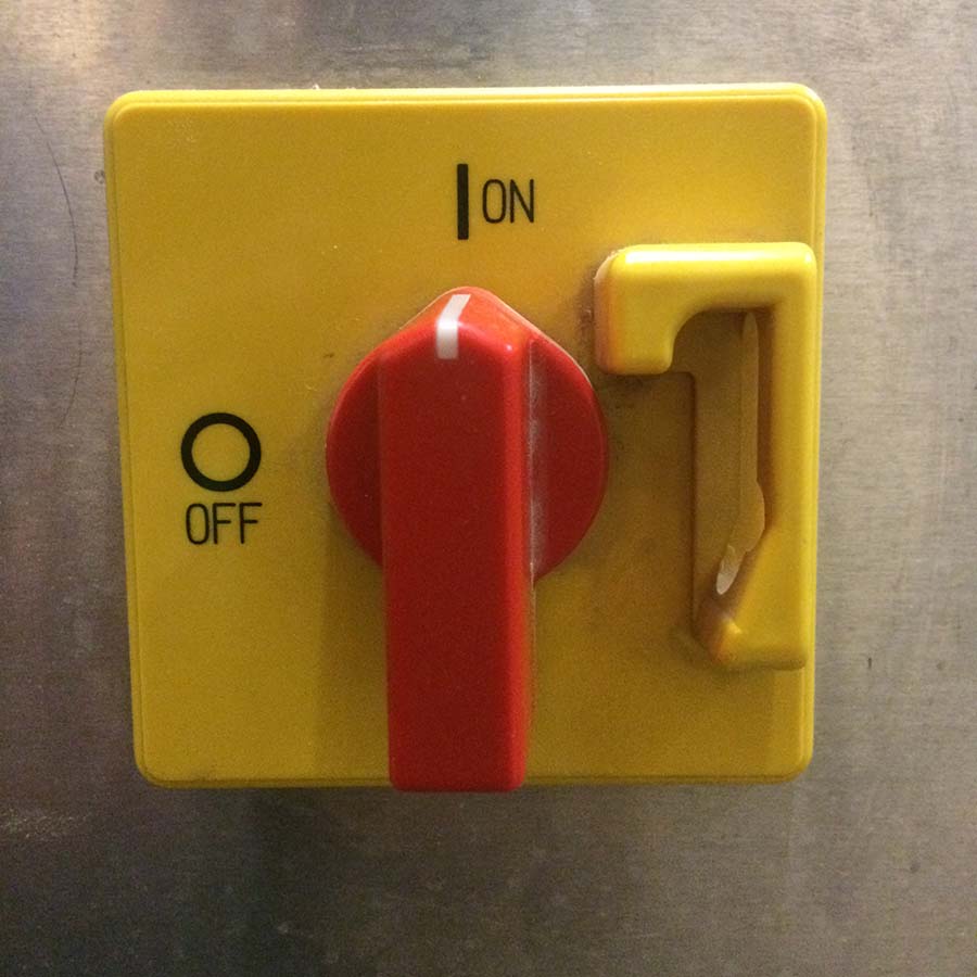
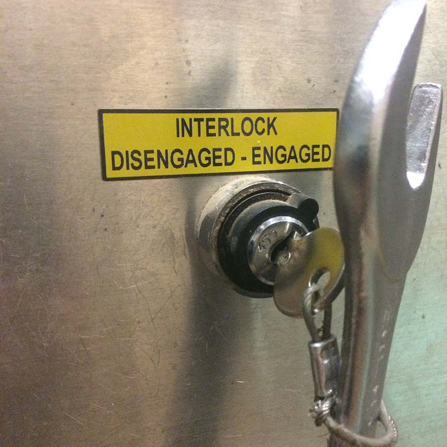
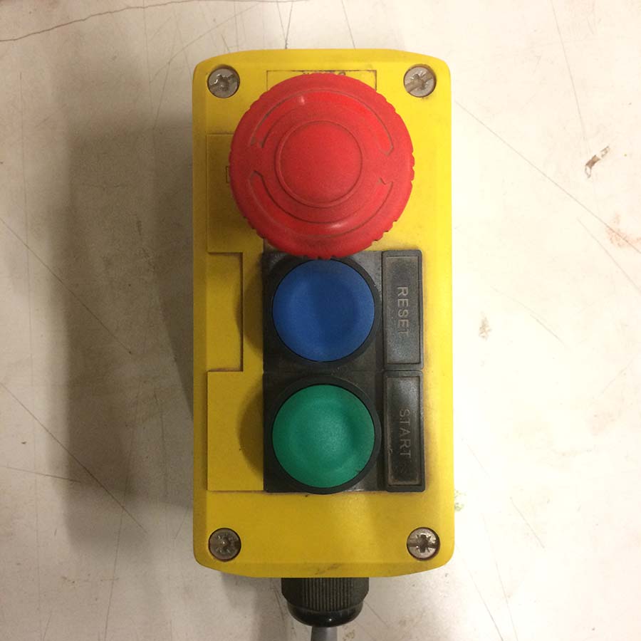
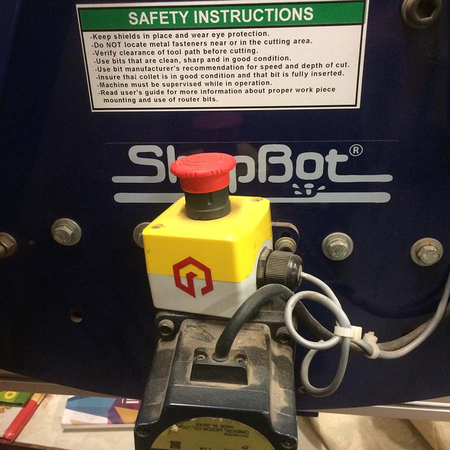
After the board is fixed on to the sacrificial board, the very first step in machining is to change the bit and then turn the switches on. Once the key is turned and engaged, the spindle shouldn't be changed. To ensure the saftey, spanners are tied with the key. There is a STOP, RESET and START button next to the workstation. It is required to keep an eye on the cutting process to avoid accidents. Another such stop button is there on the other side. Start button is to initiate spindle rotation before milling. Pushing this button is crucial before spindle gets in contact with the milling board. Failing to do so would cause spindle to break instantly. Following are the switches and key locations.
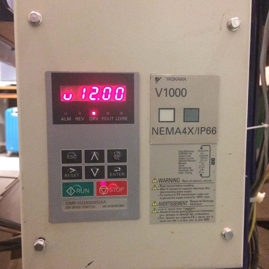
Once, everything is in place, next step is to start cutting the parts in shopbot. Before that it is required to run a spindle warmup routine.
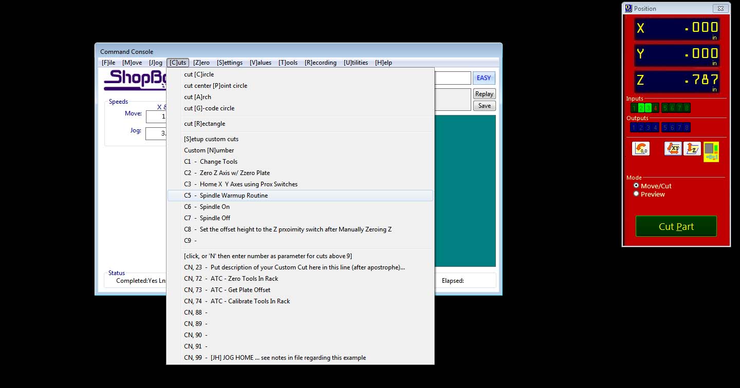
Next, XYZ locations are to be zeroed.
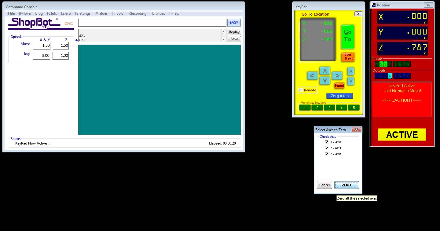
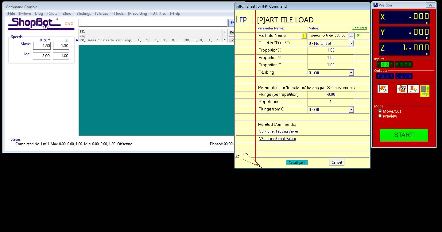
Then start button on the screen needs to be pushed.

Now, hit green colored start button on yellow control box to start the spindle. Later push the 'ok' button on the screen. If we click 'ok' 'before hitting the start button on the control box, bit will hit the milling bed and will break because spindle is not rotating. So, I ensured that I follow the sequence.
Likewise, I loaded the other toolpaths and finished milling.

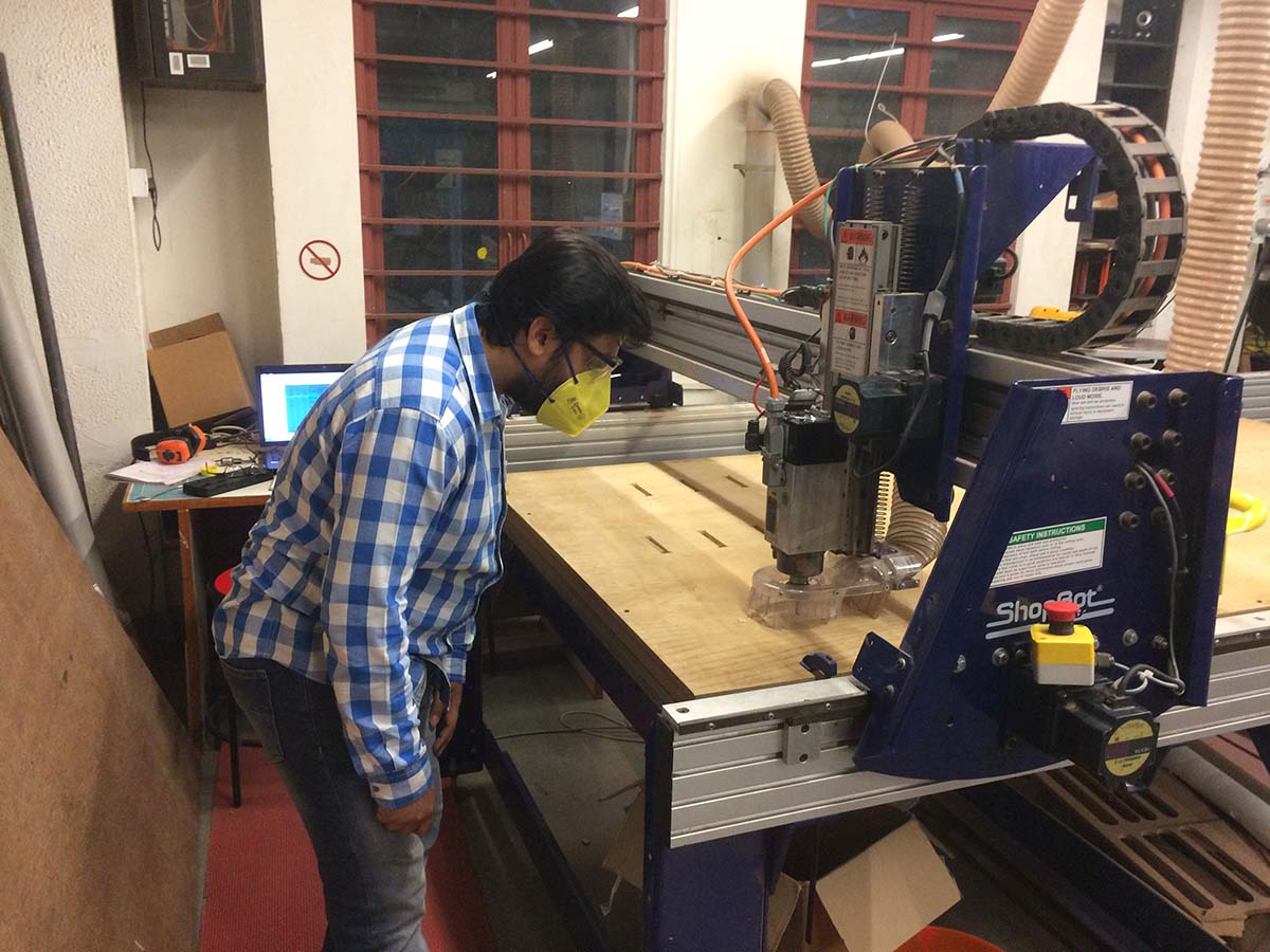
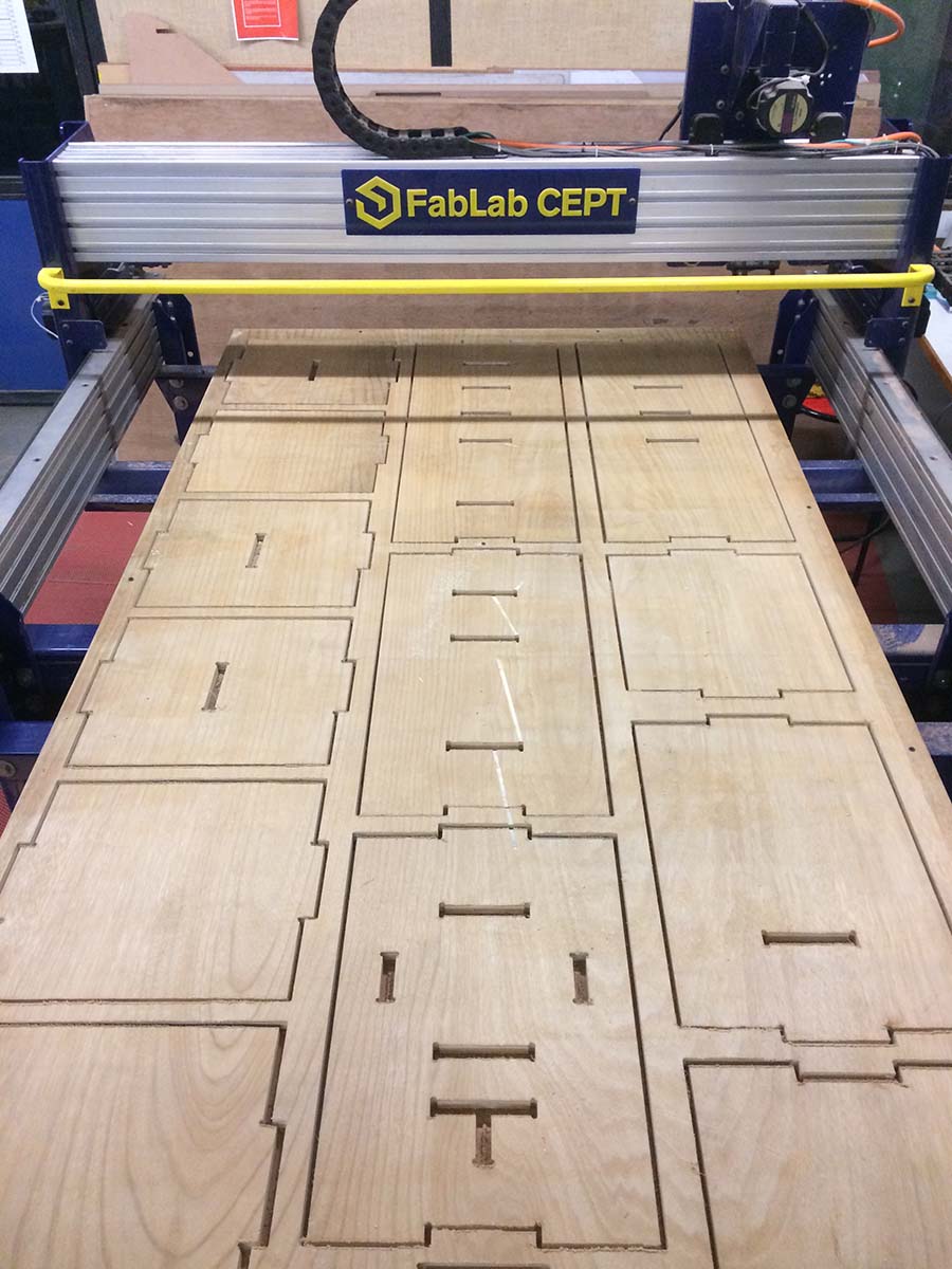
CNC Milling
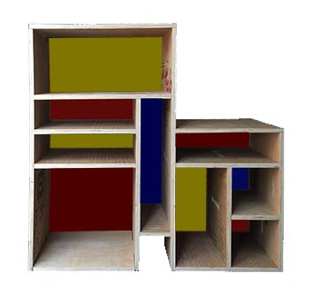
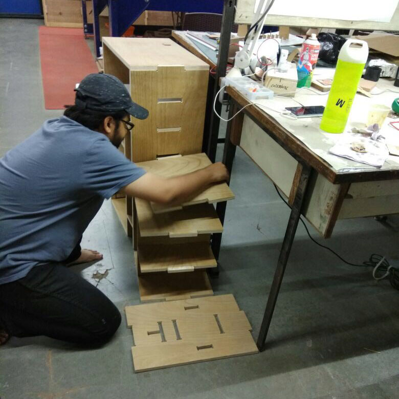
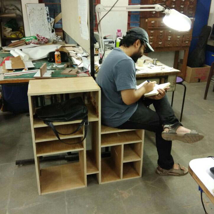
Final Object

Links
Week 7 FilesAutoCAD
PartWorks
Shopbot Tutorial