Week 15: Networking and Communications
Tasks for the week:
- Design and build a wired &/or wireless network connecting at least two processors
This week, I wanted to try networking using the Asynchronous serial communication network.
For me, my first step was to understand what is asynchronous serial communication. My fab-mate Gautam Prakash helped me with this.
As per what I understood, Asynchronous communication is basically transmitting data between two micro-controllers without using external clock signal in a steady stream.

In simple words, it is like the sequential conversation between two humans, where one asks and the other responds. Here, the communication happens between the words spoken by one and heard by the other. Similarly, the communication happens by 'RX' to 'TX' and 'TX' to 'RX'.
TX
RX
Step:01
Preparing the Bridge and Node for communication:
For asynchronous, I required a bridge circuit that could transmit data to one or more nodes by serial communication. Hence, I began by preparing the schematic diagram for the bridge and node circuit. The only difference between the components of the bridge and node is that the bridge circuit has a FTDI header to recieve commands,whereas the node doesnt. The node would recieve data from the bridge circuit by the 'RX' and 'TX' pins.
I referred to the circuit on the class site for reference.
Bridge circuit Schematic:

Components required:
Attiny 45
AVR ISP 6 pin header
4 pin SMD male header
FTDI Header
SMD LED
10K Resistor
1k Resistor
1uF Capacitor
Node circuit Schematic:

Components required:
Attiny 45
AVR ISP 6 pin header
4 pin SMD male header
SMD LED
10K Resistor
1uF Capacitor
After checking both the schematics with ERC, I proceeded further at the board diagram for both.

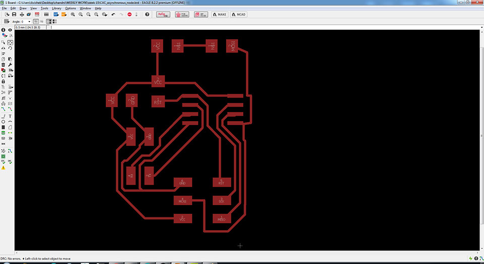
Bridge circuit Board Diagram:
I arranged the components, and autorouted the traces. Next, I checked with DRC and it showed no errors.
-crop-u51013.jpg?crc=337109901)
The parameters I followed for both the circuits in 'Net classes' can be seen above.
Node circuit Board Diagram:
I arranged the components, and autorouted the traces. Next, I checked with DRC and it showed no errors.
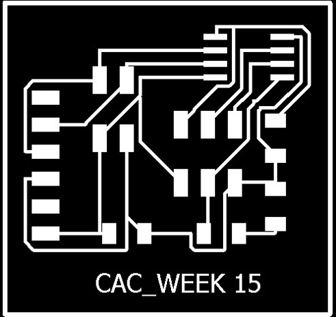

Node Circuit:
Step:02
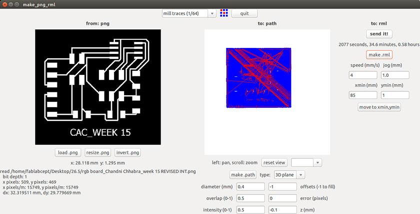
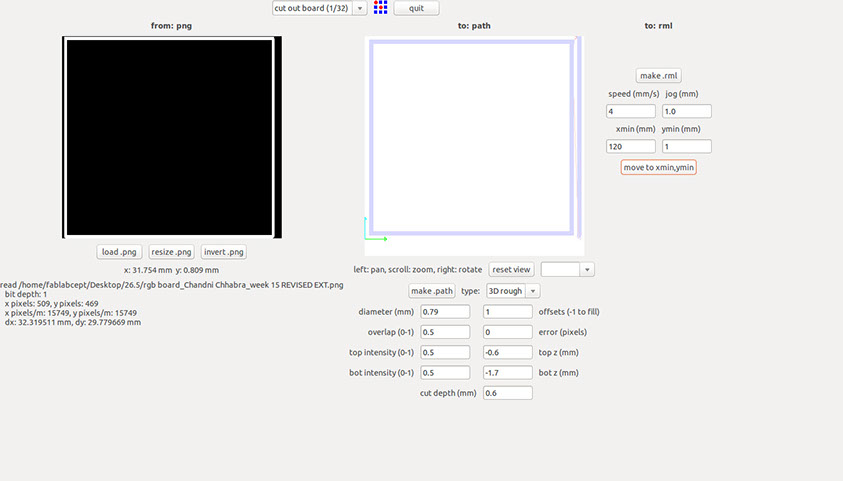
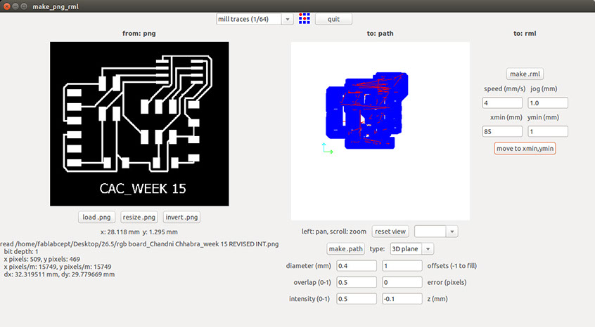
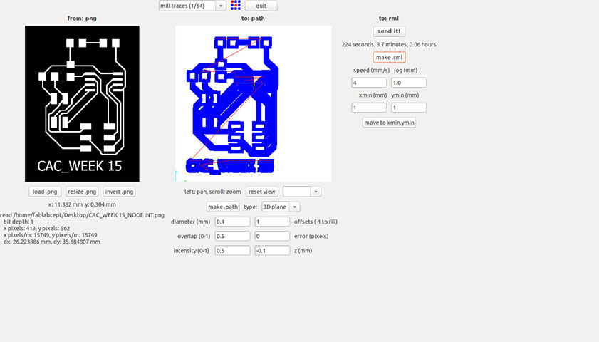
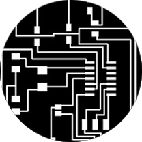
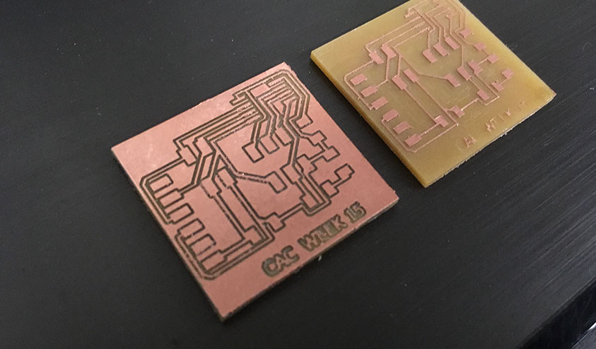
Milling the boards:
The parameters that I used for milling and the process of milling can be seen in the images below:
<
>
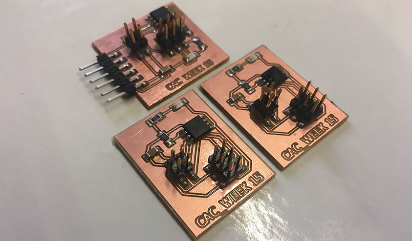
I prepared 2 bridge boards with different milling parameters and 2 node boards, just in case to avoid delay in work if one of them burns off while programming.
Step:03
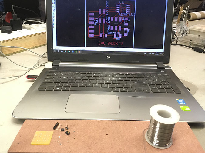
Programming the boards:
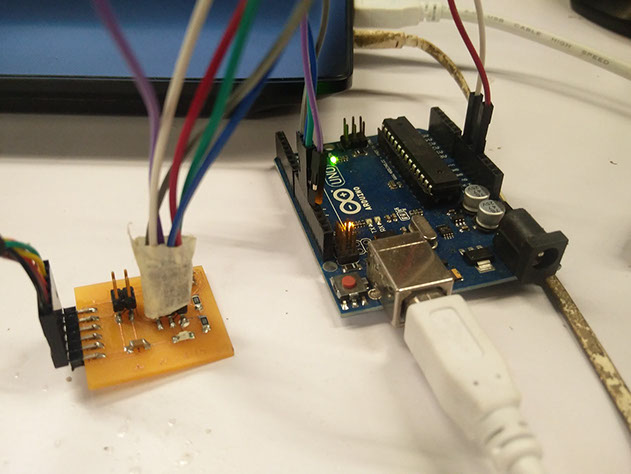
To begin with, I programmed the Arduino to work as ISP. Then, I connected my board to the arduino using the MISO,MOSI, SCK and RST pins. The image can be seen below:
Since Serial communication was required, and Attiny uses software serial to communicate, I needed to burn the bootloader. This can be done as shown in the GIF image below:
After successfully burning the bootloader, it showed me the message as seen below:
I followed the same process for the Node circuit, by burning the bootloader on it to ensure that the clock cycles match on both boards. The video below shows the same:
burning bootloader from chandni chhabra on Vimeo.
Before moving forward, I decided to check both the circuits by uploading a basic blink code form arduino examples. The video below shows the working. The codes used can be seen beside the video.
int led = 0;
void setup() {
// put your setup code here, to run once:
pinMode (led, OUTPUT);
}
void loop() {
// put your main code here, to run repeatedly:
digitalWrite(led,HIGH);
delay(1000);
digitalWrite(led,LOW);
delay(1000);
}
After this, I modified the simple blink code such that it can be uploaded on the bridge circuit to send 'H' and 'L' signal to the node circuit via Software Serial as RX-TX based on which the LED on the node circuit would turn on and off. Similarly, I uploaded the modified code that would help recieve the 'H' and 'L' signals from the bridge board on the node board.
Code for BRIDGE Circuit:
#include <SoftwareSerial.h>
#define rxPin 3
#define txPin 4
SoftwareSerial myserial(rxPin, txPin);
int ledPin = 0; // the pin that the LED is attached to
int incomingByte; // a variable to read incoming serial data into
void setup() {
//Serial.begin(9600);
myserial.begin(9600); // initialize serial communication
pinMode(ledPin, OUTPUT); // initialize the LED pin as an output:
}
void loop() {
if (myserial.available() > 0) { // see if there's incoming serial data:
myserial.println('H');
//Serial.println("H");
delay(1000);
myserial.println('L');
//Serial.println("L");
delay(1000);
myserial.println('o');
//Serial.println("H");
delay(1000);
myserial.println('k');
//Serial.println("L");
delay(1000);
}
}
Code for Node Circuit:
#include <SoftwareSerial.h>
#define rxPin 4
#define txPin 3
SoftwareSerial serial(rxPin, txPin);
int ledPin = 0; // the pin that the LED is attached to
int incomingByte; // a variable to read incoming serial data into
void setup() {
serial.begin(9600); // initialize serial communication
pinMode(ledPin, OUTPUT); // initialize the LED pin as an output:
}
void loop() {
if (serial.available() > 0) { // see if there's incoming serial data:
incomingByte = serial.read(); // read the oldest byte in the serial buffer:
if (incomingByte == 'H') { // if it's a capital H (ASCII 72), turn on the LED:
digitalWrite(ledPin, HIGH);
}
if (incomingByte == 'L') { // if it's an L (ASCII 76) turn off the LED:
digitalWrite(ledPin, LOW);
}
}
}
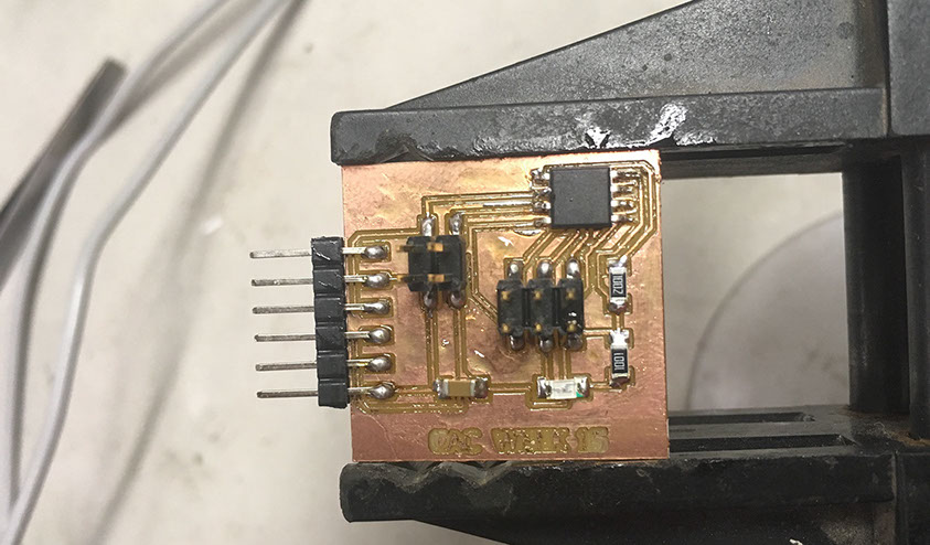
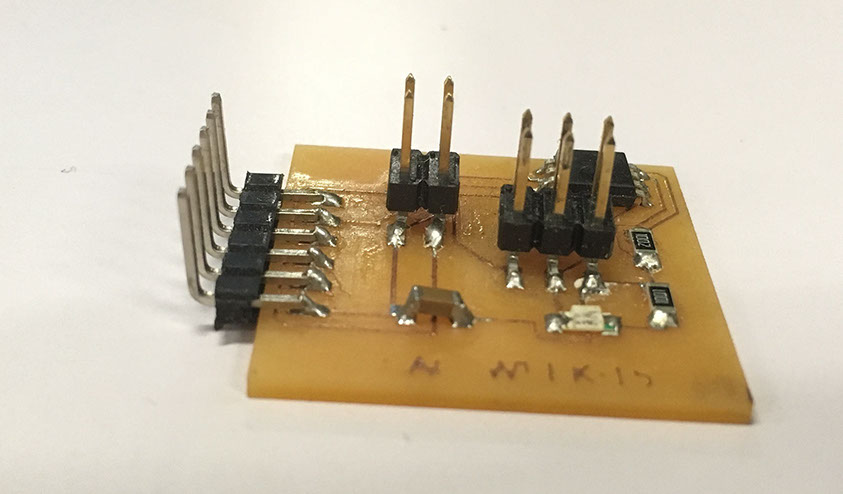
After uploading respective codes on both the circuits, I connected the Bridge circuit to power source using FTDI cable and connected the RX pin from bridge circuit to the TX pin on node circuit. Similarly, connected the TX pin from bridge circuit to RX pin on node circuit. Since, the code was uploaded and power was connected, my bridge circuit was successful to send the 'H' and 'L' signals to my node circuit, hence the LED on the node circuit blinked on the node board. The video below shows the same.

EX-TERRA-DUR by Chandni Chhabra is licensed under a Creative Commons Attribution-ShareAlike 4.0 International License.