week 15
Networking and Communication
ASSIGNMENTS:
- Design and build a wired &/or wireless network connecting at least two processors
home
networking
about me
For this assignment I have done 2 things:
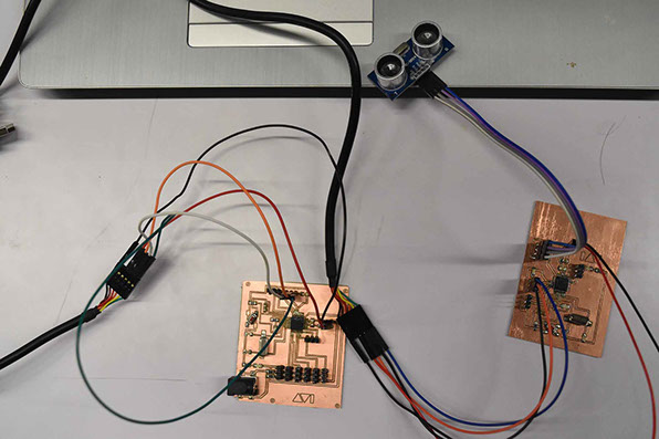
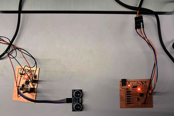
- Connecting the 2 boards (Input Device & Krab Control Board) and control the LED brightness through distance.
- For the Final Project I have used a networking setup where the Input device will act as a collision detector and shut the robot circuit if such incident happens.
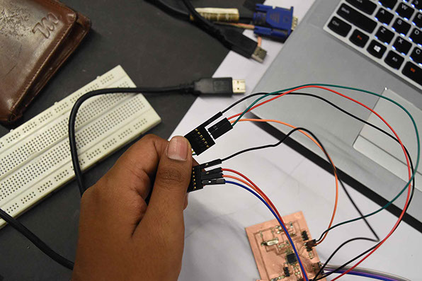
First 2 boards are connected through FTDI cable and connected to my laptop. Now, to connect the boards in between them I took the RX of input Device and connected to TX of the Krab Board and took RX of Krab board and connected to TX of the Input Device. This was absolutely experimental but it actually worked and did the purpose.
contact
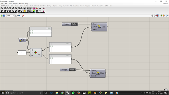
Here the Input device board acts as the Master and krb board acts as the slave board ad communicates using TX, RX and GND. And the each board is identified as their used COM port that has been flagged in grasshopper and separated using List item to identify as master and slave.
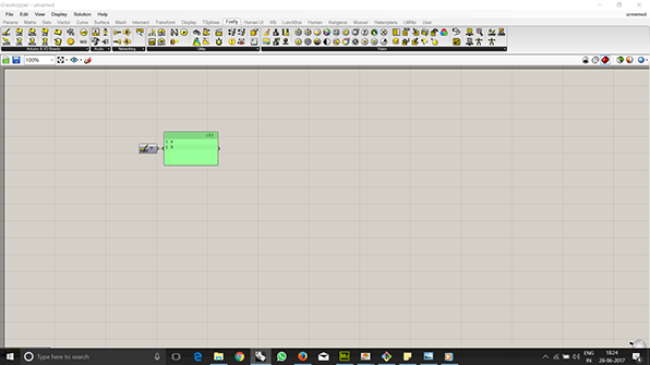
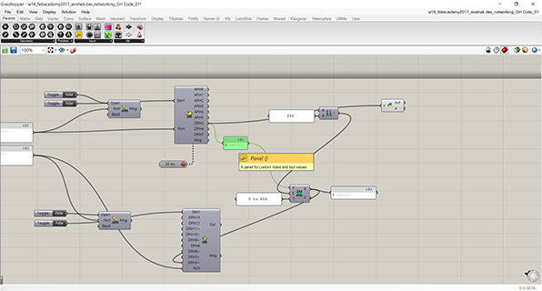
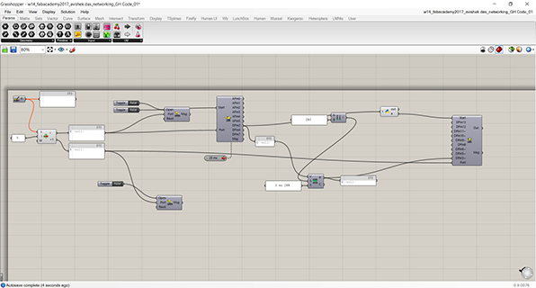
Next Grasshopper was set up to read the data from one board and transmit to the other.
Now there are 2 ports that are open. So the file will need to be written to accommodate that.
List Item was introduced to separate the ports.
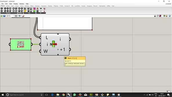
Port open and get the Uno read and Write components.
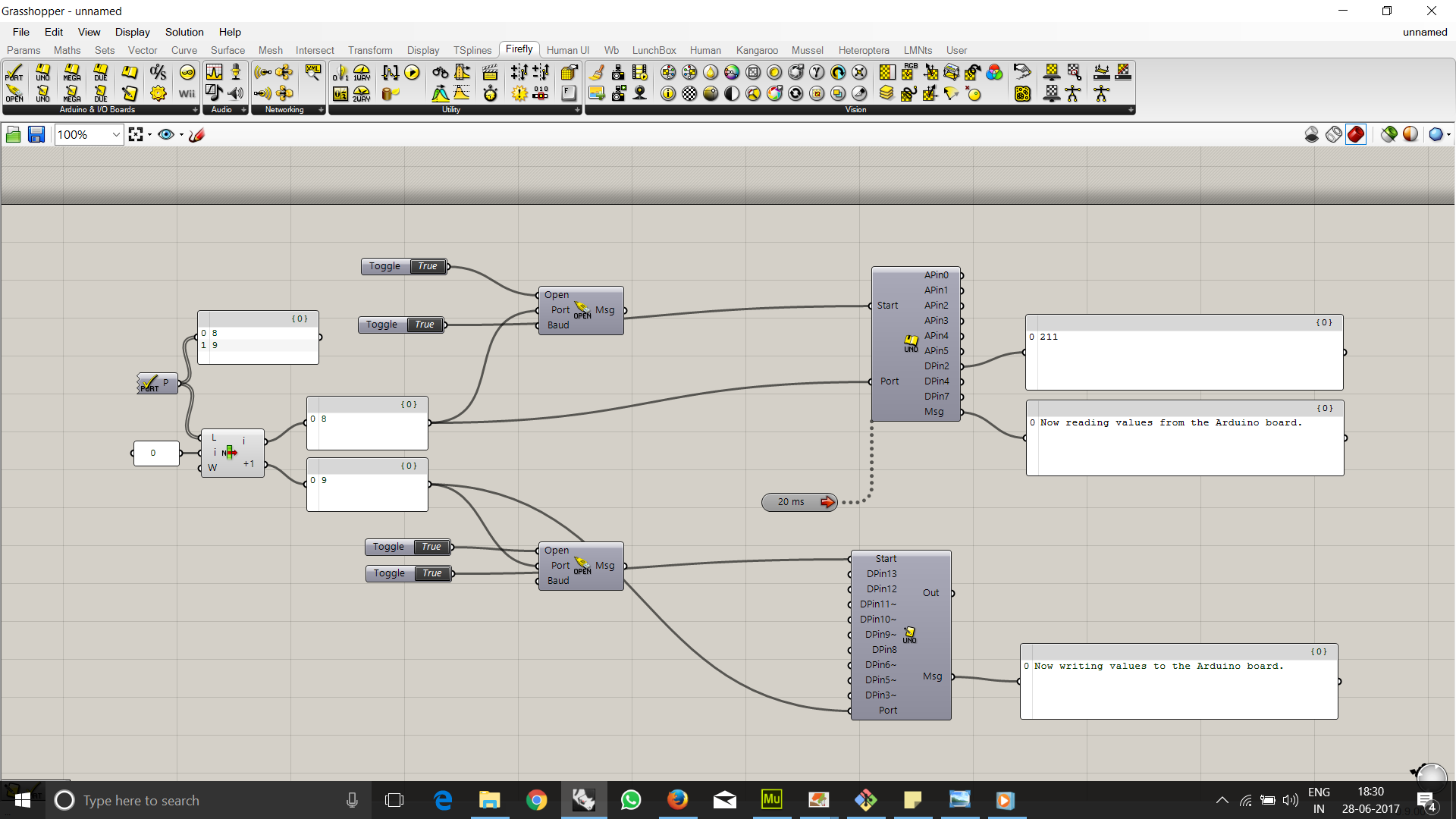
Now we can see the value being generated from the ultrasonic.
The value in this room goes maximum to 212 cm. So we set a upper limit of 300 and remap the values 0-300 to 0-255 while the 0-212 will be mapped into the new domain
This was connected to Pin 3 of Uno Write using PWM mode.
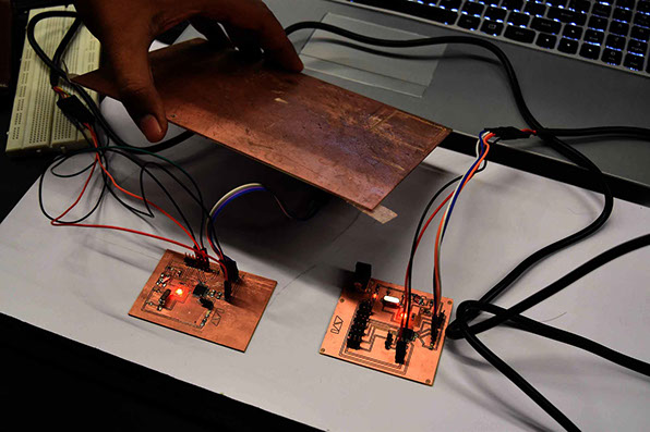
In the picture it can be seen that the brightness is clearly different.
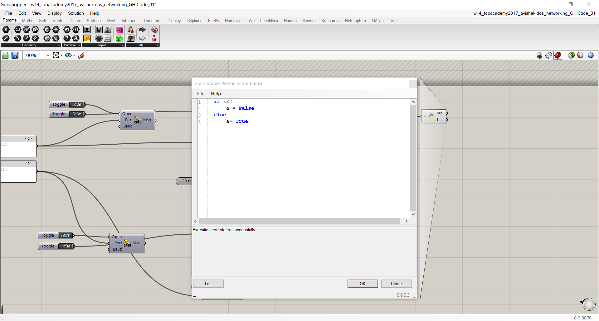
A small python code was written to detect limit of the Robot in the 2nd part. It is 2cm. If it comes near about 2cm the robot circuit will be shut of and had to be restarted manually. So far it is manually, I havent found any automated solution in this tine at least.
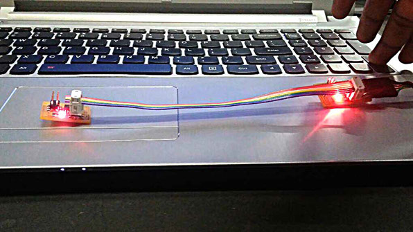
The workflow between 2 circuits can be seen in the next video:
The working files can be obtained from here.
asynchronous node
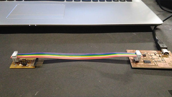
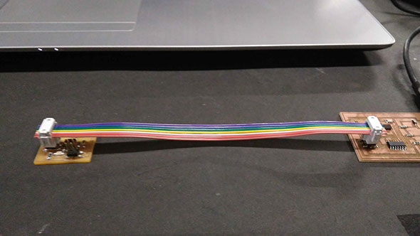
To show proper network between two I had to do Neil's example of Asynchronous Node and bridge. Using Neil's board image I have milled and soldered one Bridge and one Node .
These are ATTiny45 based boards.
As I have understood from the lecture, Its like calling name within a range of people and whose name comes up they respond and it registers the name.
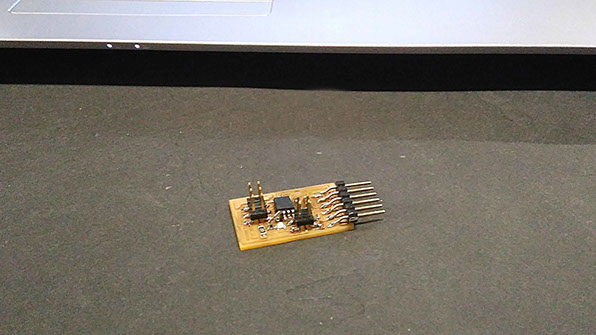
Bridge Board.
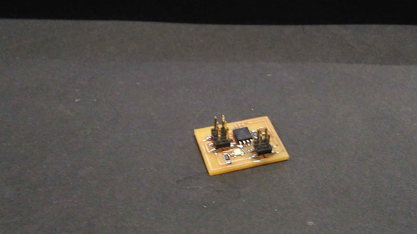
Node Board
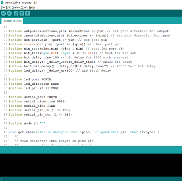
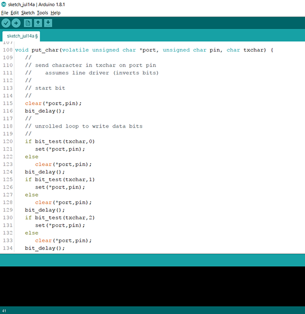
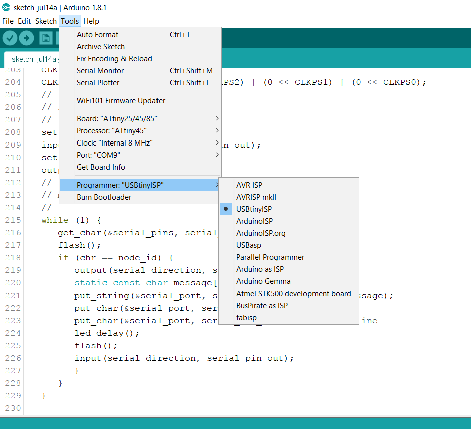
I had to program these 2 boards using the C file Neil has given. I have used Arduino IDE and FabISP to program the boards. Here I will try to explain the programming process and the code in order to understand the logic. Here we have used the same code to multiple boards but changing the values.
understanding the code
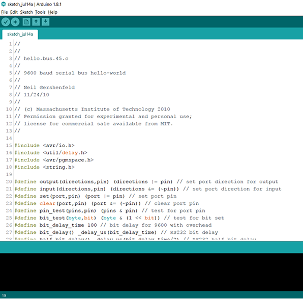
This is the most important part to understand in order to get the desired output. The desired baudrate for the serial communication is 9600.
The first part declares all the variables like which pin to use, directions for input, delay , serial input pin, serial output pin etc.
The next part acts as an address / unique name for the board. by which if we call it will respond back.
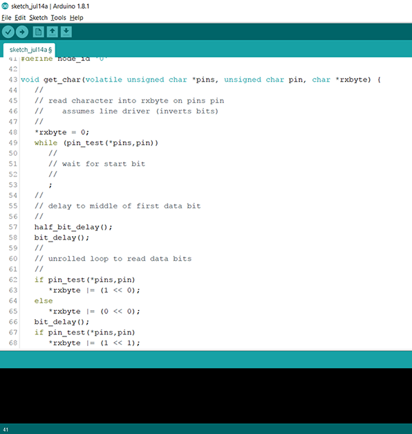
Here in this part of the code Void get char ():
the program tries to read if any data is coming in the receiving ports and checks each pin pf ATTiny.
Tests the data received against the sent data
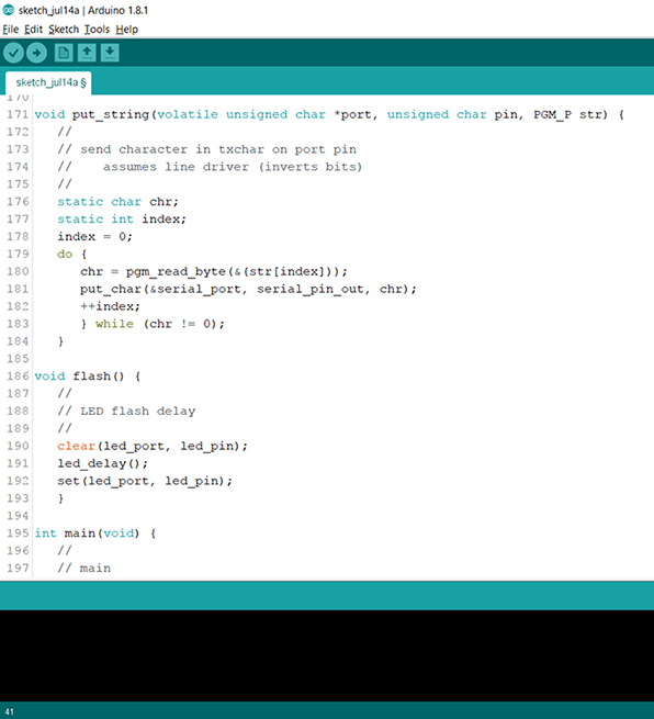
From which node its coming and reading the byte and LED blinking technique
Tests the byte, flashes the LED and sends the data back to serial port in a format "node-xxx"
Fabisp to program
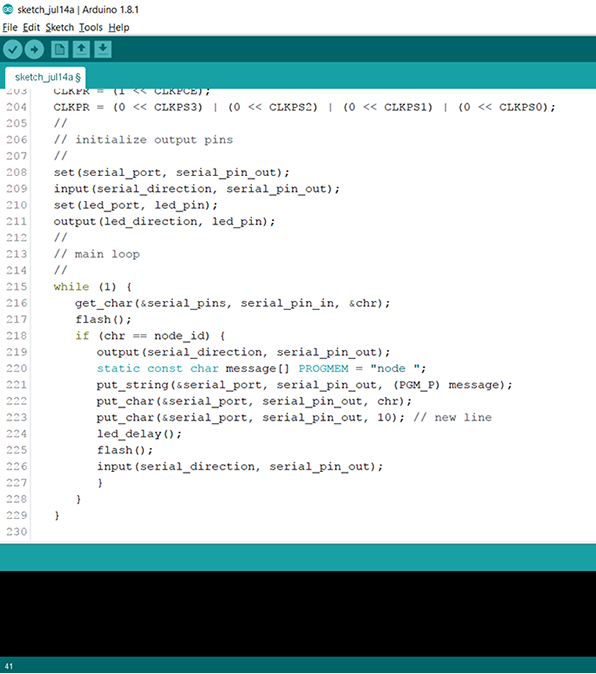
Bridge and Node are programmed in the following setting. While Bridge is 0 Node is 0.
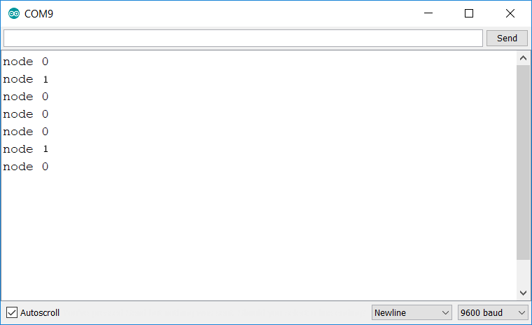
No if i open Serial monitor in arduino and put 0,1,0,0,0,1,0 it will look like following
This week's file can be accessed here.
go to WEEK 16 >>
Avishek Das | 2017 | FabLab CEPT