Mechanical Design, Machine Design machine that make machines
Presentation
Demonstration video
The proof of concept video is further down on this page.
Teamwork
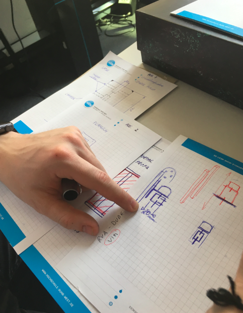
This is a group assignment. Some how we didn't divide our assignment in three proper pieces. We just went into our workshop and start working together. We were just sure about two points: CNC-Milling-Machine and trying to sketch the frame and mechanical parts with maker beams and additional technical parts and through milling, turning 3D-printing missing parts. It came out as very inspiring and effective. All of us thought about design and mechanics and started to build and draw and test together and across and helping each other. I can recommend this way of real !Design Thinking!
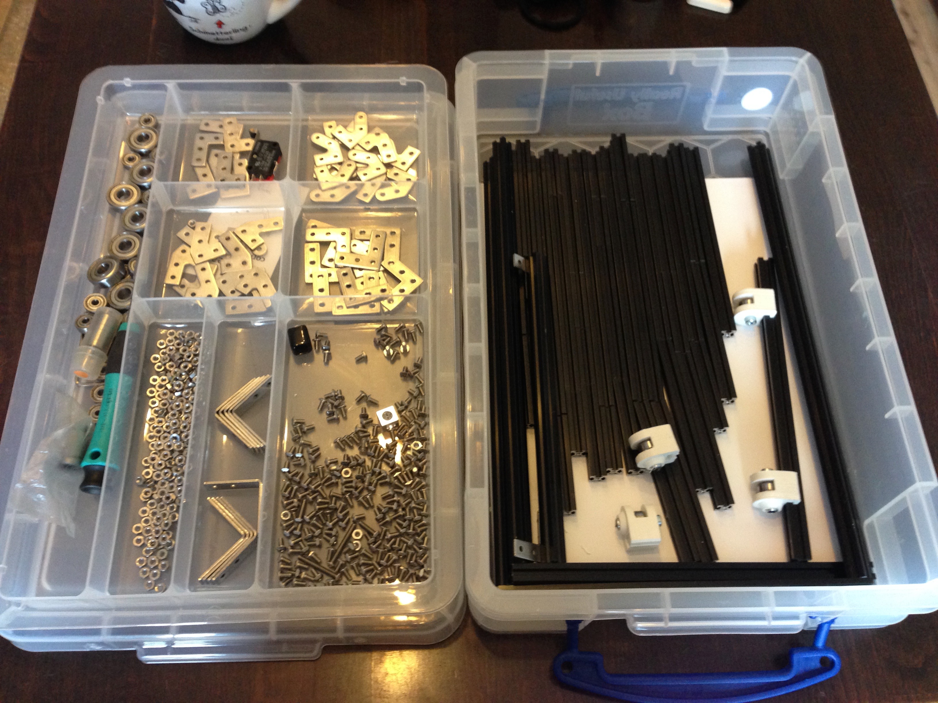
Tools what we used to fulfill the task
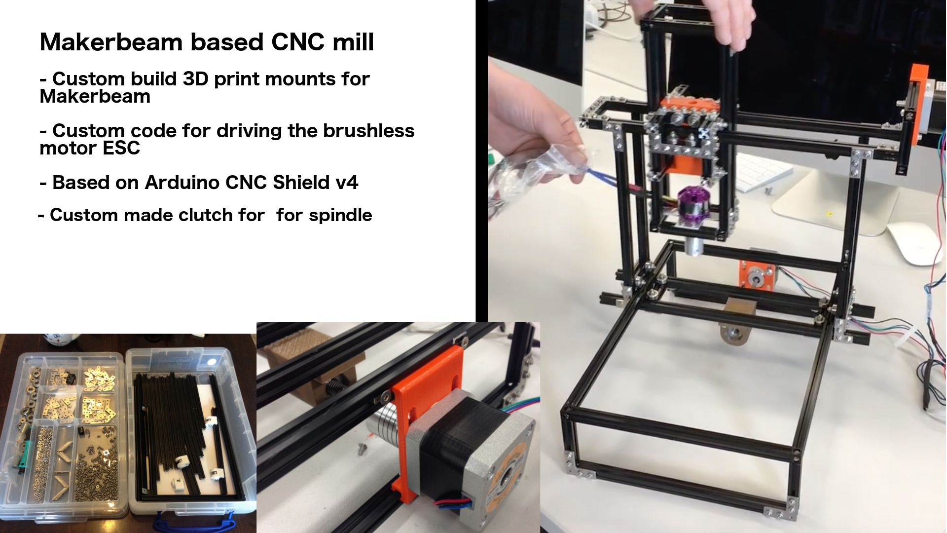
Makerbeam
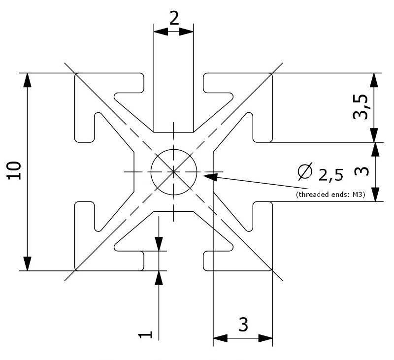
The Makerbeam project deals with the idea to be a easy to use and for its small size stable modeling option. It consists of aluminium profiles that comes in several sizes with a footprint of 1x1cm.
Fusion 360
Fusion 360 is from Autodesk. It's similar with Inventor but it's cloud based. The best advantage that it has in comparison with Inventor is, that it can be installed on my Mac. So I can use it at my Windows workstation at home and on the go on my Macbook.
Makerbeam rapid building structures
Makerbeam is a toolkit of various aluminium profiles that can be easy attached to each other by using specific screws that fit into the profiles. There are also a lot of add-on parts that can be used to build all kind of stuff. For example there a bearings, joining plates in several angles and linear bearings. All together is a very universal toolkit to build all kind of structures, machines and frames for your projects.
Starting this weeks project we were using the Makerbeam rapid prototyping dev kit. At first we were testing some methods and start a construction to become a feeling about how large the machine will be and what is possible with this kit.
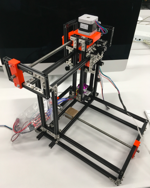
Building a moving frame for CNC milling machine First drawings and thinking through building
Here we are and do first tests with the Makerbeam dev kit. We tried multiple ways of how are the best way to realize the axis of the CNC we are building.
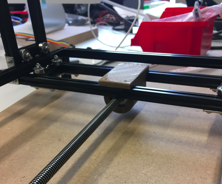
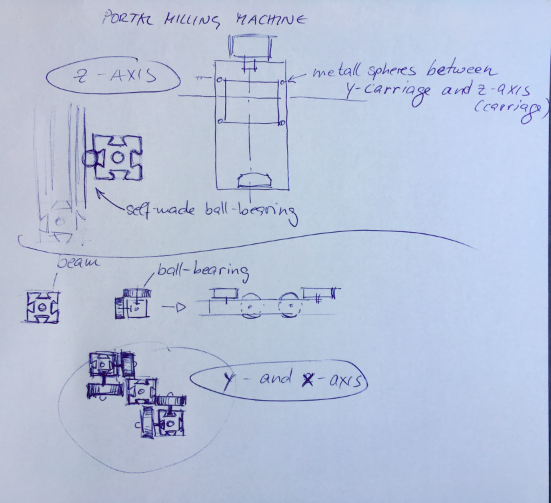
At first we try the linear rails that we had with the set of Makerbeam parts. Later we dropped this idea and build our own guiding / movement rails with a construction of bearings. We add eight bearings for every side of the rail to give the CNC only one level of freedom.

At first we set the frame and thought about our sliding system. Later we get rid of the sliding system and build our own with ball bearings that worked better and was more stable.
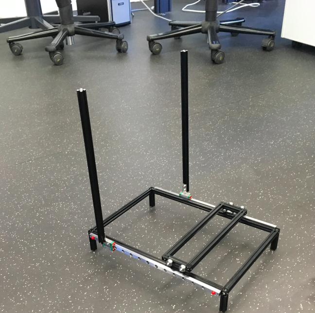
We decided to build our own sliding system with ball-bearings.

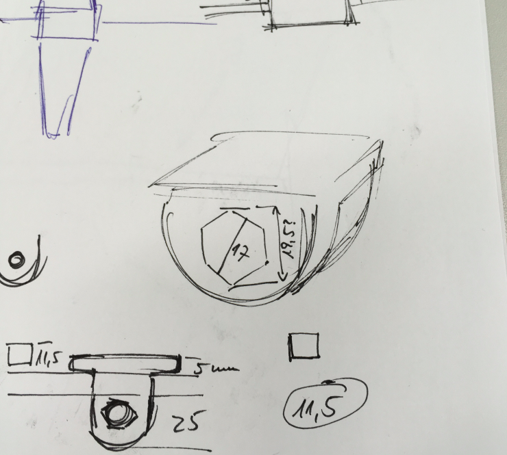
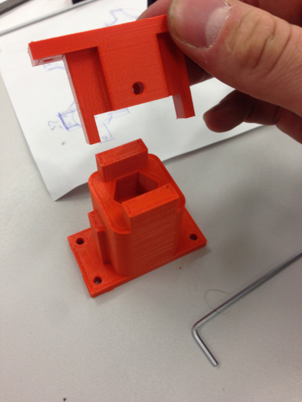
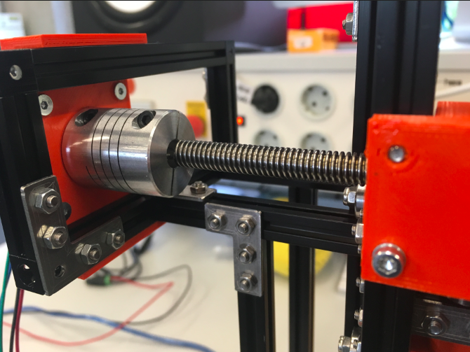
Our trapezoidal threads, which we want to use, will be fixed through individual designed 3d-printed hanger.
Objects designed in Fusion came out quite precise, only a bit of post-processing. The nuts for trapezoidal threads fit in nearly perfectly.
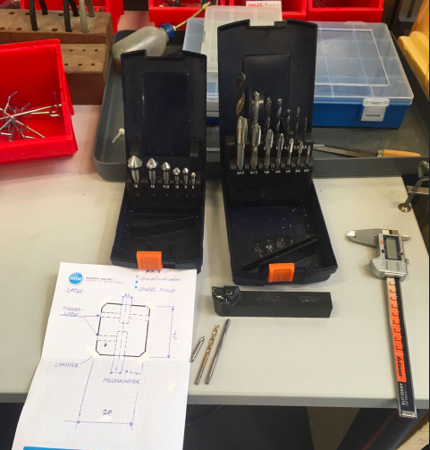
Turning a holder on a lathe for our milling cutter


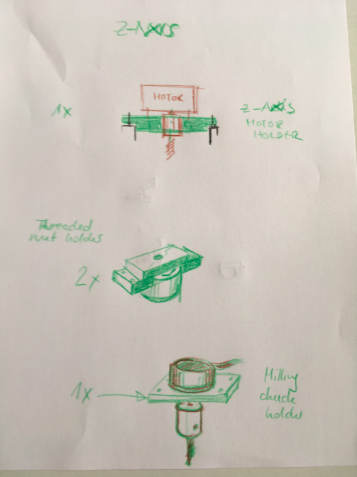
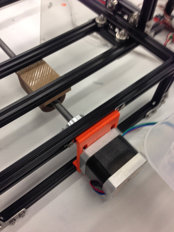
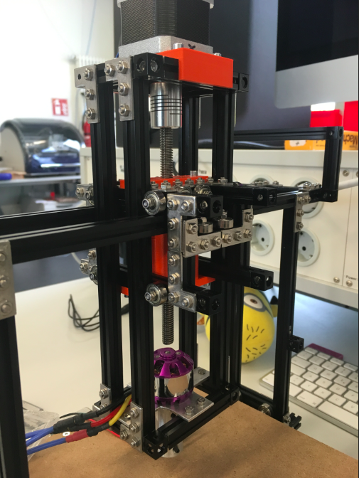
Building the z-axis. The main idea keeping the number of different components low, makes it simpler for building up but for the construction more difficult, as we had to figure out how to move the z-axis easy and save with an trapezoidal thread spindle. We decided to fix the spindle central. What happens? Now, we have a case like frame structure sliding with ball bearings on the horizontal y-tracks. Also, this case will be used as the socket for moving the z-axis.The stepper-motor for the z-axis will move not only the milling cutter but also itself up and down. Betwixt seized slides a vertikal case frame construction holding the stepper motor on the top and the spindle motor at the bottom.


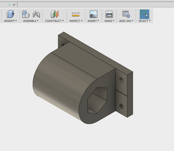
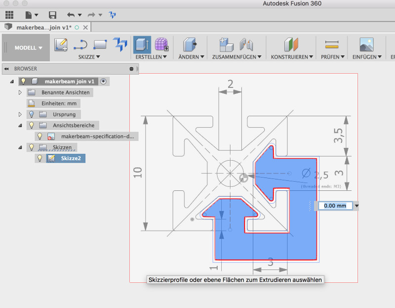
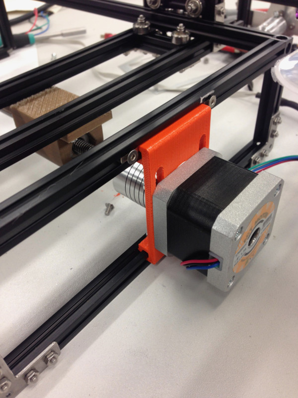
Designing the mounts using Fusion again
With the frame set up whats left are the mounts for the electronic parts like the brushless motor and and the stepper motors. I used Fusion360 again to design them. First I downloaded the footprint of the Makerbeam and and the Nema17 motors from the internet. After creating a new project I added the image of the Makerbeam footprint to the x/y plane. In the dialog that appear when adding the image I also told fusion to set the opacity of the image to 50% to be able to see through the image and to draw on it easier to the the lines I drew.
When the images is now placed on a plane Fusion add a new entry in the file browser for the construction image. Now whats left is to scale the image to it's real world size. To do so I right click on the image in the file browser and select calibrate. Now I select two positions on the image where I know the exact size of and enter this size in the dialog that appears.
The result is a image in my model where I am able to sketch on. This technique helps in the modeling process to preview the building on the footprint and see if the part is really fitting in the real world.

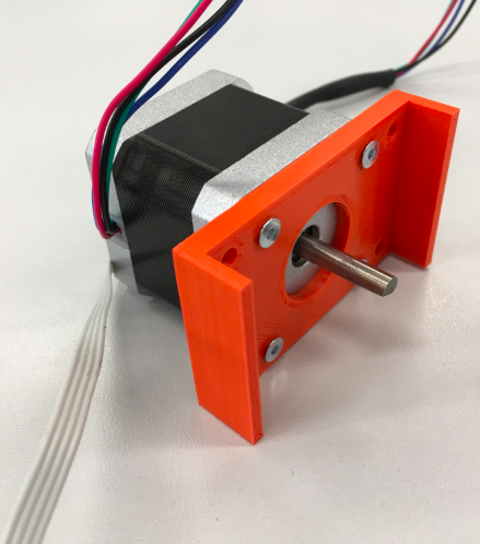
The parts I designed comes in two variants. The first one is a mount with the motor fixed in one position and the second one has larger holes for the screws so that the motor can be moved for 1cm. This is to calibrate the axis to prevent bending of the rod.
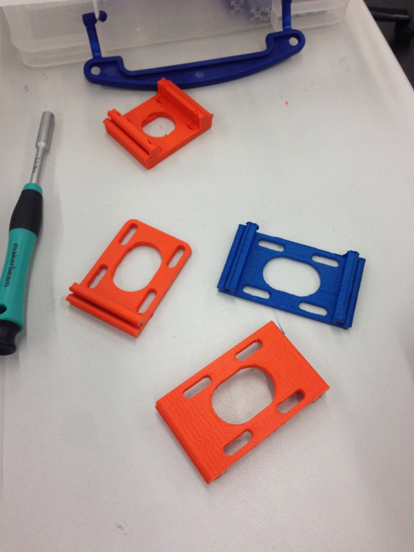
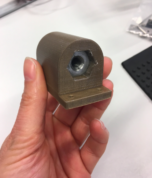
This results in several test prints. The overall problem is, that the tolerance of the printed material was often to hight and even this a modeled tolerance of 0.1mm on the teeth of the mounts. Thats why I had to reprint the model again and again and increase the tolerance of the part until it pressfit into the makerbeam profile without any space between the mount the the aluminium profile.
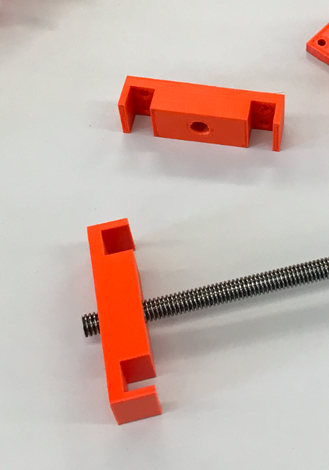
Design of the nut mount holding the nut in place

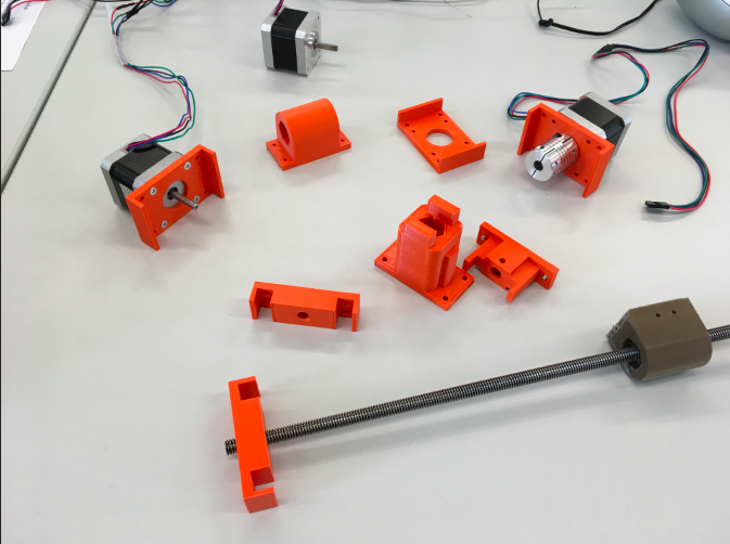
Final Design of all Holdings
The idea for the above motor holdings was very nice but somehow the 3d printing output was not satisfying to much waste. We had 4 printed holdings and only one really fit in the makerbeam system with both sides. So we decided to design a simple and easy to install mount. Please see below all 3d printed elements for our machine:


Please, see below some assembling details:
Vernier Adjustments and final assembling
As we developed two different types of ball bearings it was very important to adjust the whole frame suitable to the ' maker beam' system. It was very easy to adjust everything. Just squeezing in the small metal spheres for the z-axis was a bit tricky, but not too much. You can see below two drawings. One about the construction with ready made ball bearings and one about the idea squeezing metal spheres between z-axis beams and the head beams of the y-axis.
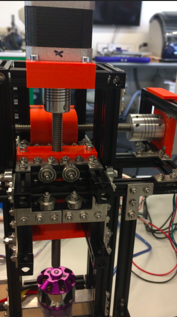
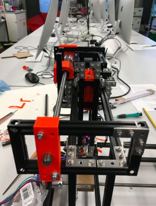
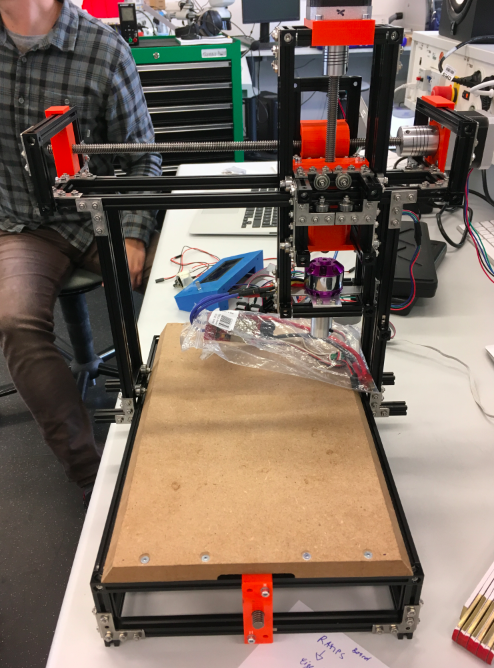
Different perspectives show the assembled machine and the wooden plate mounted as milling ground.


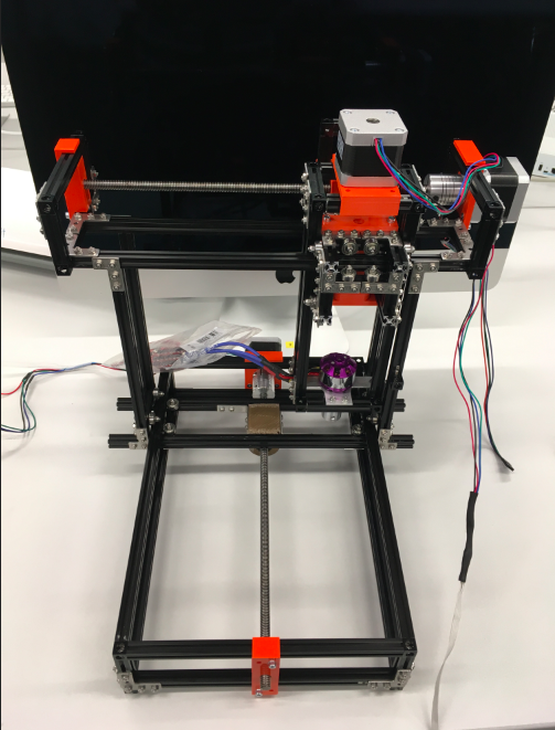
Testing stepper motors for XYZ and clearance of the trapezoid threads
Setup the motor Arduino and ESC board
In our project we want to use a brushless motor to drive the mill. Because the motor is controlled by an ESC controller I first want to give the motor a test drive to be sure that it can be handled later in the project.

Below is the test code the initialize the ESC of the brushless motor. I hooked up a Arduino to a potentiometer and a brushless motor.
#include  <Servo.h>h;// include the servo library

Servo servo;  // create servo object

unsigned long starttime;
unsigned long interval = 100000; //Intervall in Mikrosekunden
int val = 25; // Current value

void setup(){
  Serial.begin(115200); // initialize the serial connection for debugging
  starttime = micros(); // remember the start time
  servo.attach(3);  // init the pwm on port 3
  servo.write(25); //Is used to init the ESC
  delay(2000);  // wait the seconds
}

void loop(){
  if ((micros()- starttime) >= interval){
    servo.write(val); // set the value of the motor
    Serial.println(val);
    starttime = micros();
  }
  val = map(analogRead(A0), 0, 1023, 30, 110);
  servo.write(val);
}
Download section stuff to download
| ESC init script (Arduino) | download |
Setting up the CNC board firmware and software
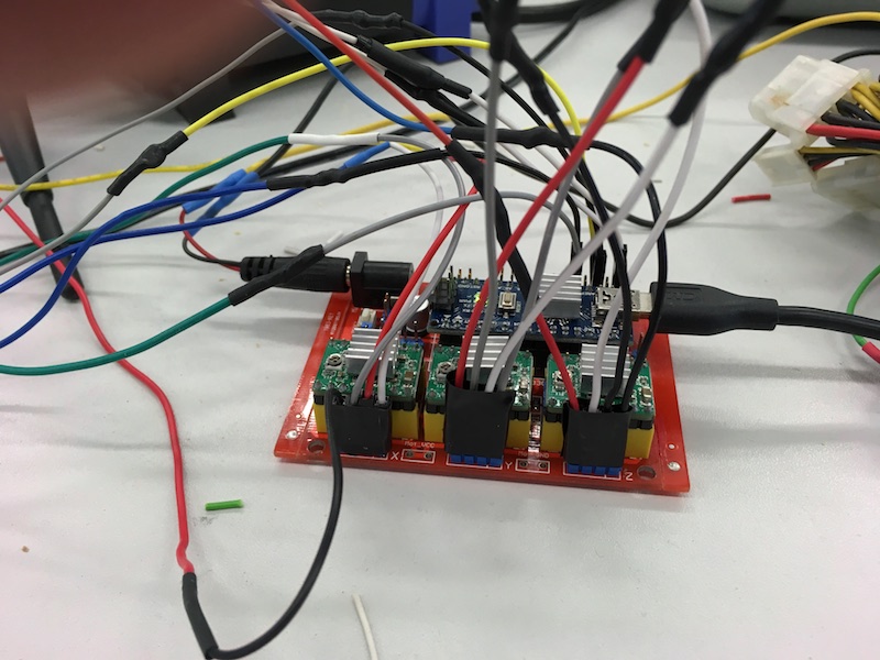
To control the machine movement we are using a Arduino CNC shield with the GBRL firmware installed. The the software on the computer is Universal gcode sender. We ordered a cheap CNC shield from amazon. The heart of it is an Arduino Nano. The Arduino uses a firmware that translate the commands that are send to it by the Universal Gcode Sender. The firmware on the Arduino is GRBL. Is opens a serial connection in bandwidth 115200. The Universal Gcode Sender can connect to the Arduino with a USB cable. After it is connected the Universal Gcode Sender is able to send commands to the firmware to move the stepper motors with help of the stepper motor driver.
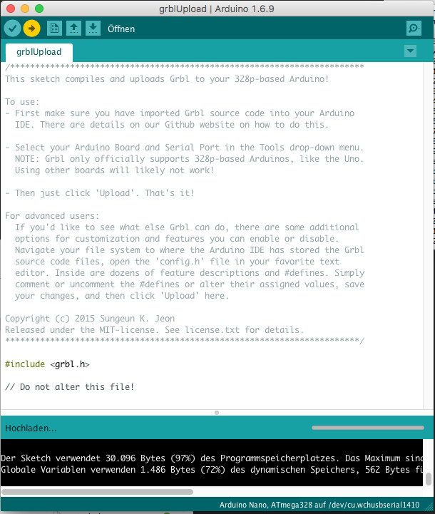
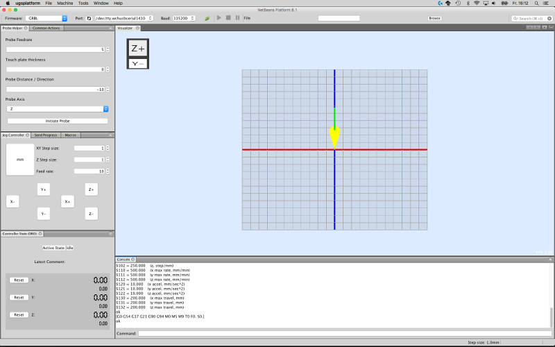
The images above shows the flashing process and the Universal Gcode sender connected to the Arduino.
Moving the axis with gbrl studio
Here we move the the axis and set the machine to zero with gbrl studio
Motor speed control
The result was that after the initialization I can be control the speed of the motor by the potentiometer. I also opened the serial monitor to plot the current value of the motor speed.
Proof of Concept
Here we mill a simple circle g code file into a 4mm wood-plate
Download section parts we made
| Nema17 Makerbeam mount f3d (Fusion360) | download |
| Nema17 Makerbeam mount (stl) | download |
| Nema17 Makerbeam mount 1cm versatile f3d (Fusion360) | download |
| Nema17 Makerbeam mount 1cm versatile (stl) | download |
| MTM partlist ods | download |
| Thread-holder | download |
| Motor-mount | download |
Setting up the CNC board firmware and software
To control the machine movement we are using a Arduino CNC shield with the GBRL firmware installed. The the software on the computer is Universal gcode sender. We ordered a cheap CNC shield from amazon. The heart of it is an Arduino Nano. The Arduino uses a firmware that translate the commands that are send to it by the Universal Gcode Sender. The firmware on the Arduino is GRBL. Is opens a serial connection in bandwidth 115200. The Universal Gcode Sender can connect to the Arduino with a USB cable. After it is connected the Universal Gcode Sender is able to send commands to the firmware to move the stepper motors with help of the stepper motor driver.
The images above shows the flashing process and the Universal Gcode sender connected to the Arduino.
Possible Improvements
Four main aspects:
- Security
For general security it would be good to build up a protective panel in the hight of the vertical travel distance. This aspect leads to the next point: - Housing
It would be nice and good to have housing around the machine and controller because of dust formation. - Screw Locking
This maker beam system needs a lot of screws and nuts. Even if we screwed the nuts very tight, it is too dangerous to run the machine for a long time without any security fixations. The nuts tend to loose themselves. To prevent this there are two possibilities:
First, using lockwasher with double-sided radial fins or locking springs or clip washer. This is advisable for detachable connections.
Second, screw locking by spezial adhesives like 'Loctite'. - Vibration damper
The high frequency of the rotating cutter head should be cushioned by vibration dampers like appropriate muffling material. For example vibration depressing tape from '3M&'. Or just very thin foam rubber.