03. Computer Controlled Cutting
Assignments
- Cut something on the vinylcutter
- Design snap fit joint design & cut it using laser cutter
Vinyl Cutting
I decided to cut the sticker which I have designed last week (2D design) using Inkscape. Here is the sticker image..

Our local instructor taught us how to operate the vinyl cutter. Then, using the .dxf file generated in last week I started the vinyl cutting.
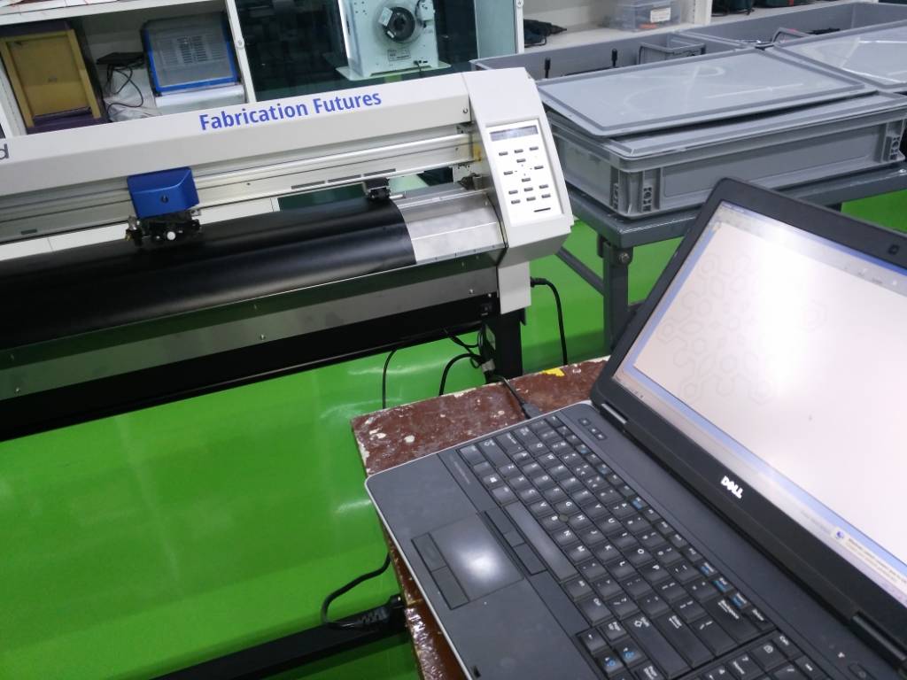
Here is the image of vinyl cutter which we have i our lab.
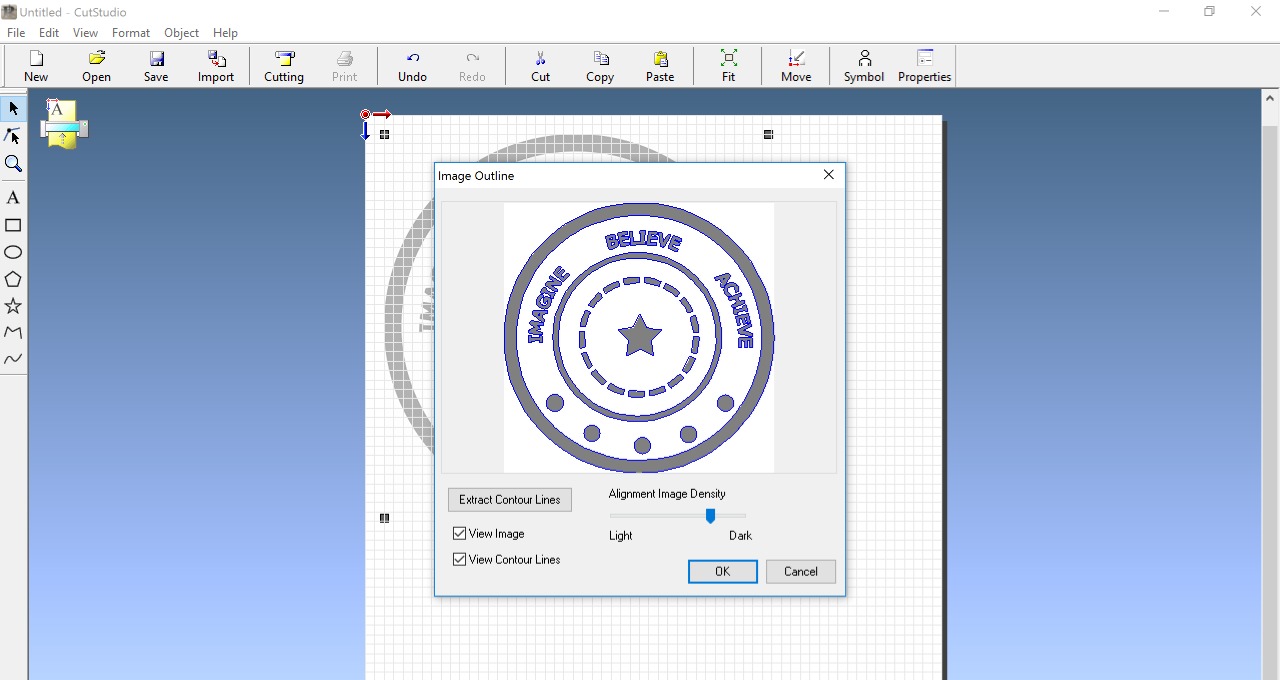
We used cut studio to convert the image into vector format. (i.e. to trace the outlines of the image). The cut studio converts image into g-code format which is then given to vinyl cutter.
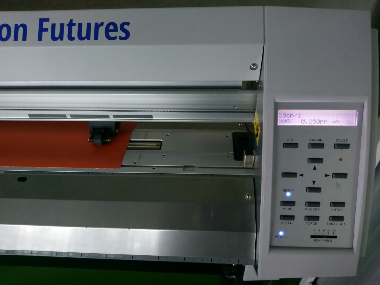
Then I kept following settings for vinyl cutting :
1. Cutting speed = 20cm/s
2. Force = 90gf
3. Width of cutting edge = 0.250mm
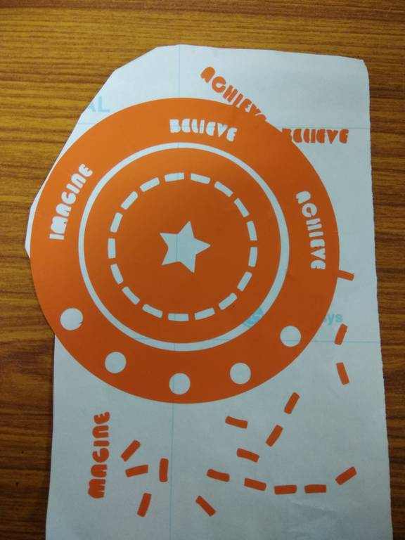
While cutting I had kept force less, so few shapes were not cut properly. Hence I had tough time while removing the unwanted parts. (specially the letters) I used tweezer to remove those unwanted parts.
Here is the sticker...
Laser Cutting
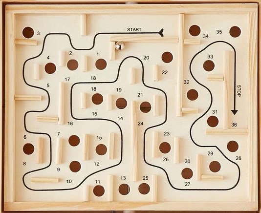
I decided to design a labyrinth maze for lazer cutting assignment.
I tried to use equations for dimensions whereever possible. This provides flexibility to change the dimensions & design will be updated automatically. But I could not succeed in making it fully parametric. I am still working on this part.
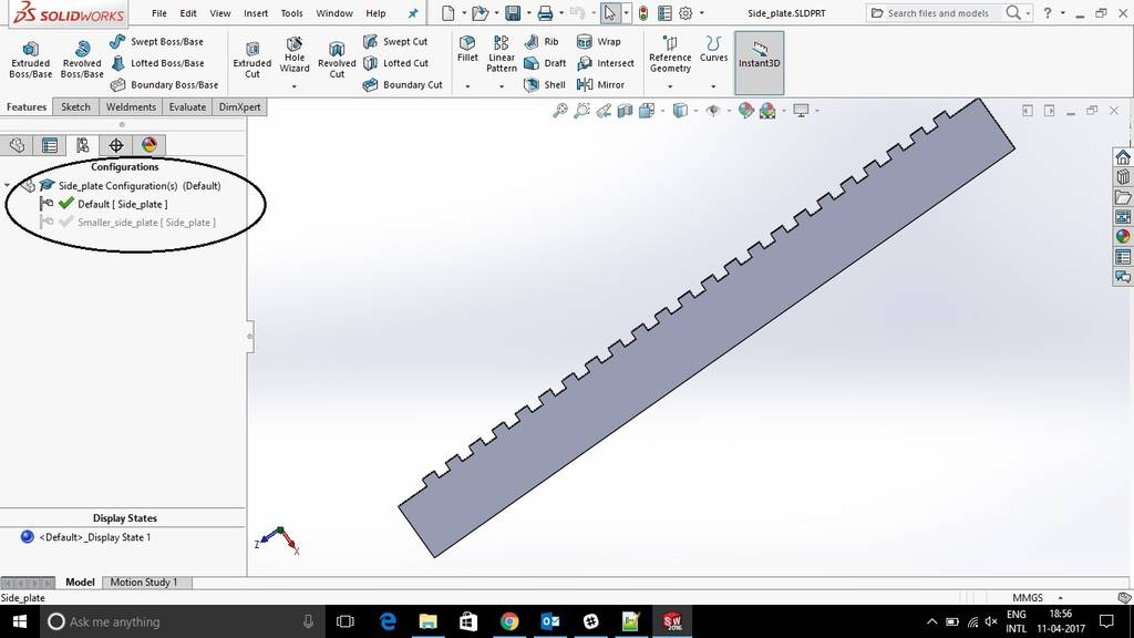
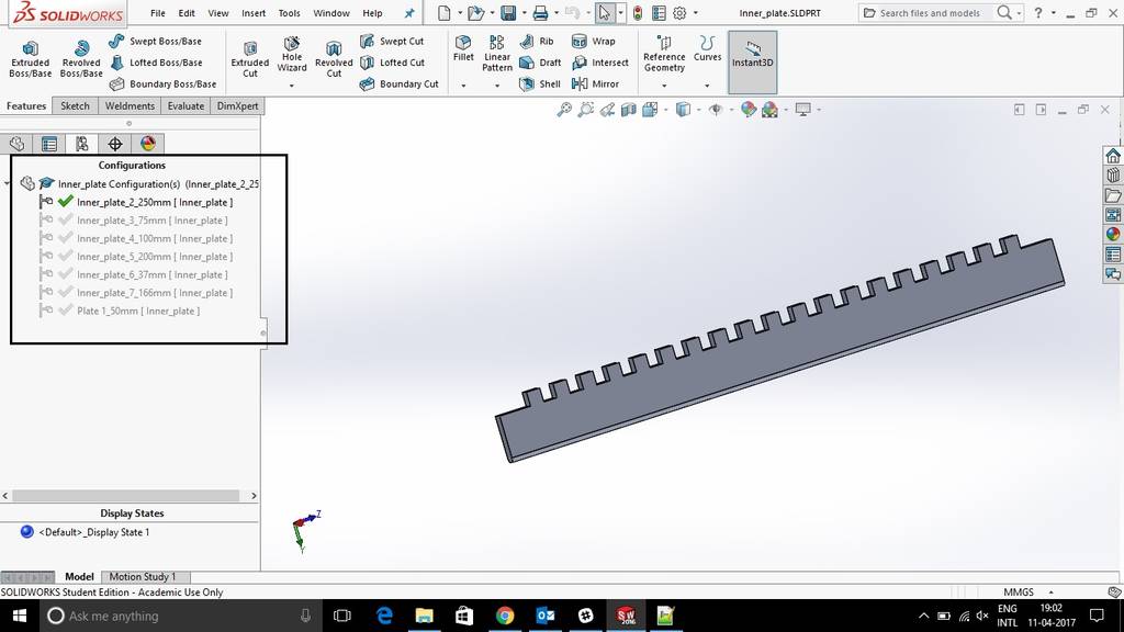
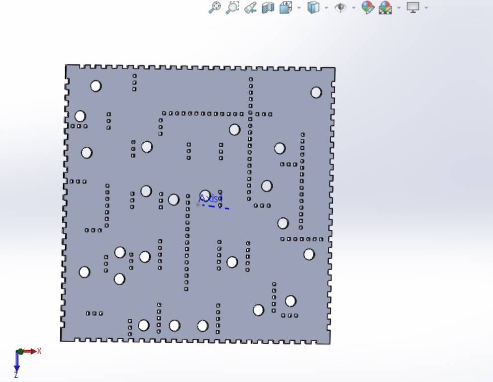
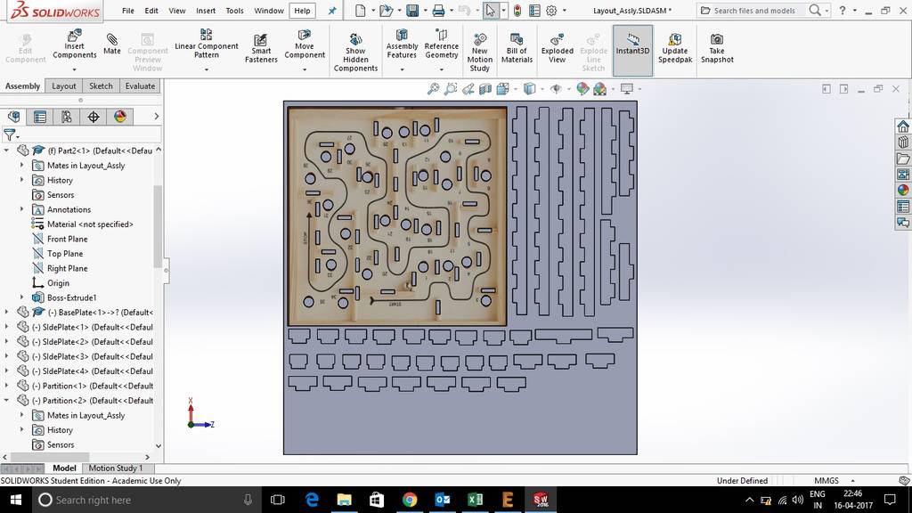
I designed the different parts required for the design as shown below. I used configuration feature of solidworks to create similar plates having different lengths.
Here is the final labyrinth maze assembly in solidworks.
Tolerance to ensure proper fitting
To ensure proper fitting between different parts, I kept tolerance of 0.3mm. This value of tolerance was decided by using trial and error method
Creating Layout File
Here I created a plate of 5 feet x 5 feet and then put all parts on this plate. Using this method we can create layouts in solidworks assembly
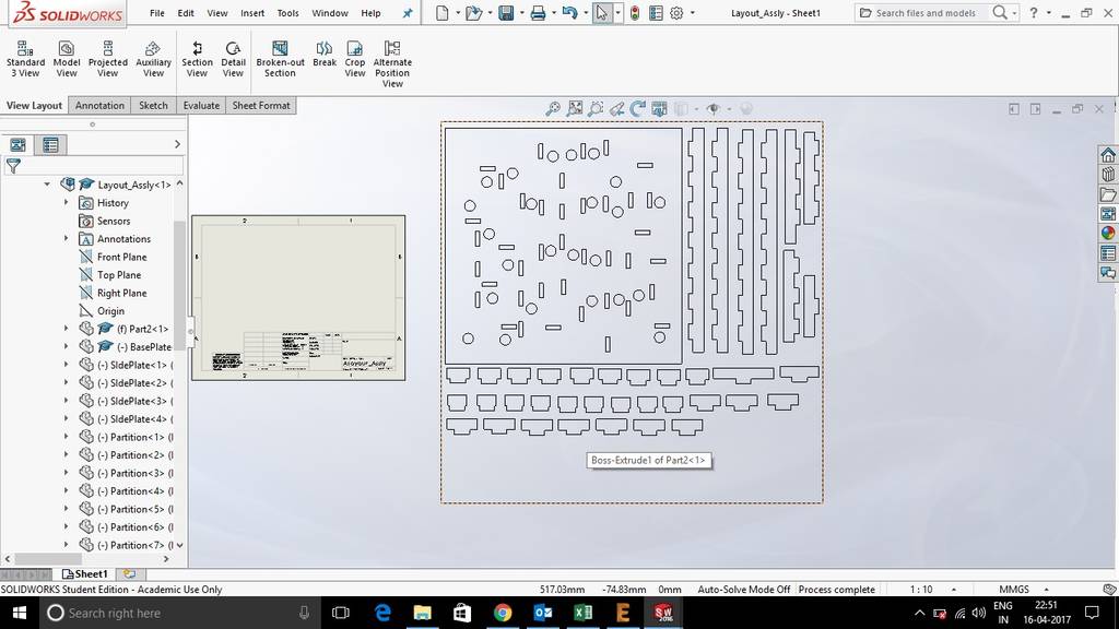
Creating DXF file
In solidworks, we cannot export assembly directly into dxf file. However, it is possible in part mode.
Hence I have created Drawing file (.SLDDRW) then exported it to dxf from drawing file.
Here is the dxf file..
Cutting the parts using laser cutter & assembling them
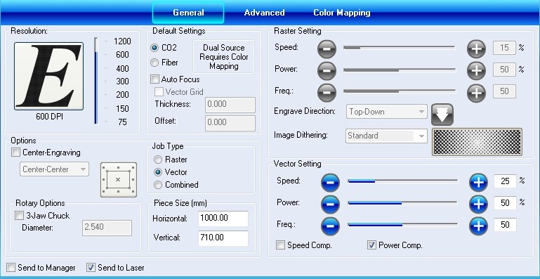
Then, we cut the parts using laser cutter. These are the settings which I kept for laser cutting -
1.Resolution = 600DPI
Our was CO2 laser, hence selected CO2
Job type = Vector (Since all cuts were straight lines, so selected vector)
Vector Settings -->
Speed = 25%, power = 50% & Frequency = 50%
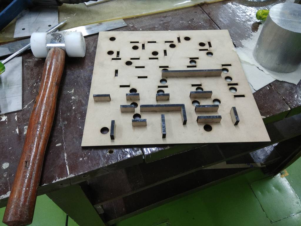
Here are the parts received after laser cutting...
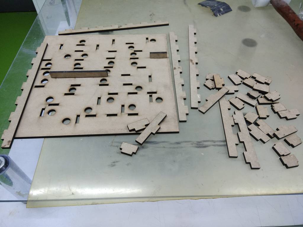
Then, I assembled the parts. THe fitting was proper. I have used 0.3 mm clearance.
Here are the images during assembly..
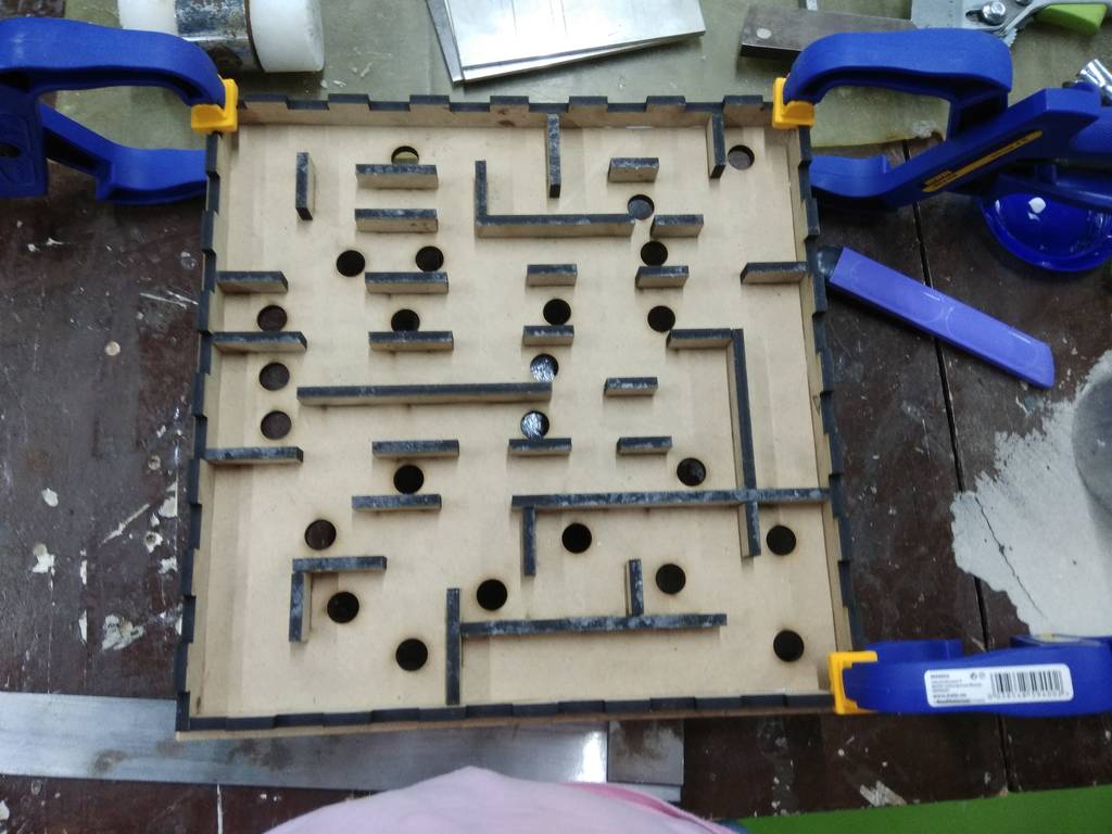
Here is the finished product...
You can download files here...
- BasePlate.SLDPRT
- Partition.sldprt
- SIdePlate.sldprt
- BaseBoxAssly.SLDASM
- Final Maze.SLDASM
- Layout_Assly.SLDASM
- Layout_Assly.SLDDRW
- Layout_Assly.DXF
- equations.txt
- Sticker_design.dxf
- Sticker_design.svg