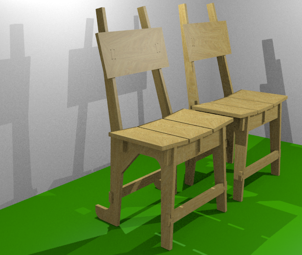
This is what planned
Model made using solidworks. Rendering done using blender.
Files for download
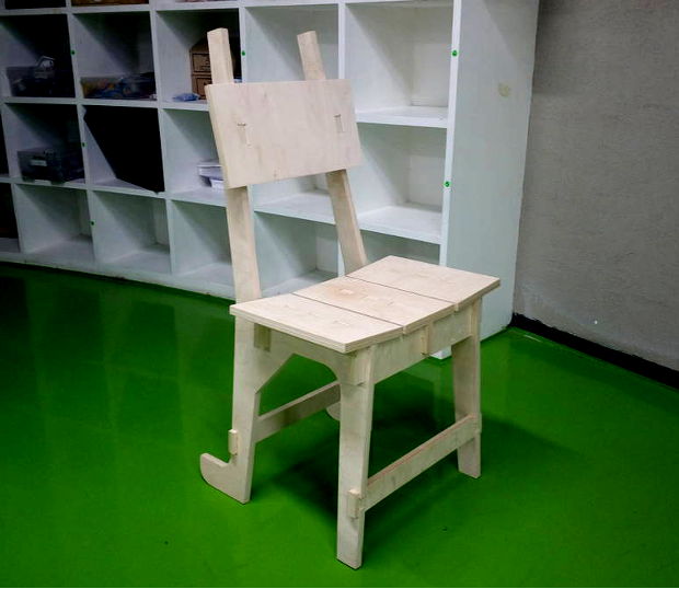
What is achieved
A chair with all snap joints
Created model and assembly using solidworks
What is different this time?
This time I have created all models in assembly mode. It helps to visualise fittings of all models
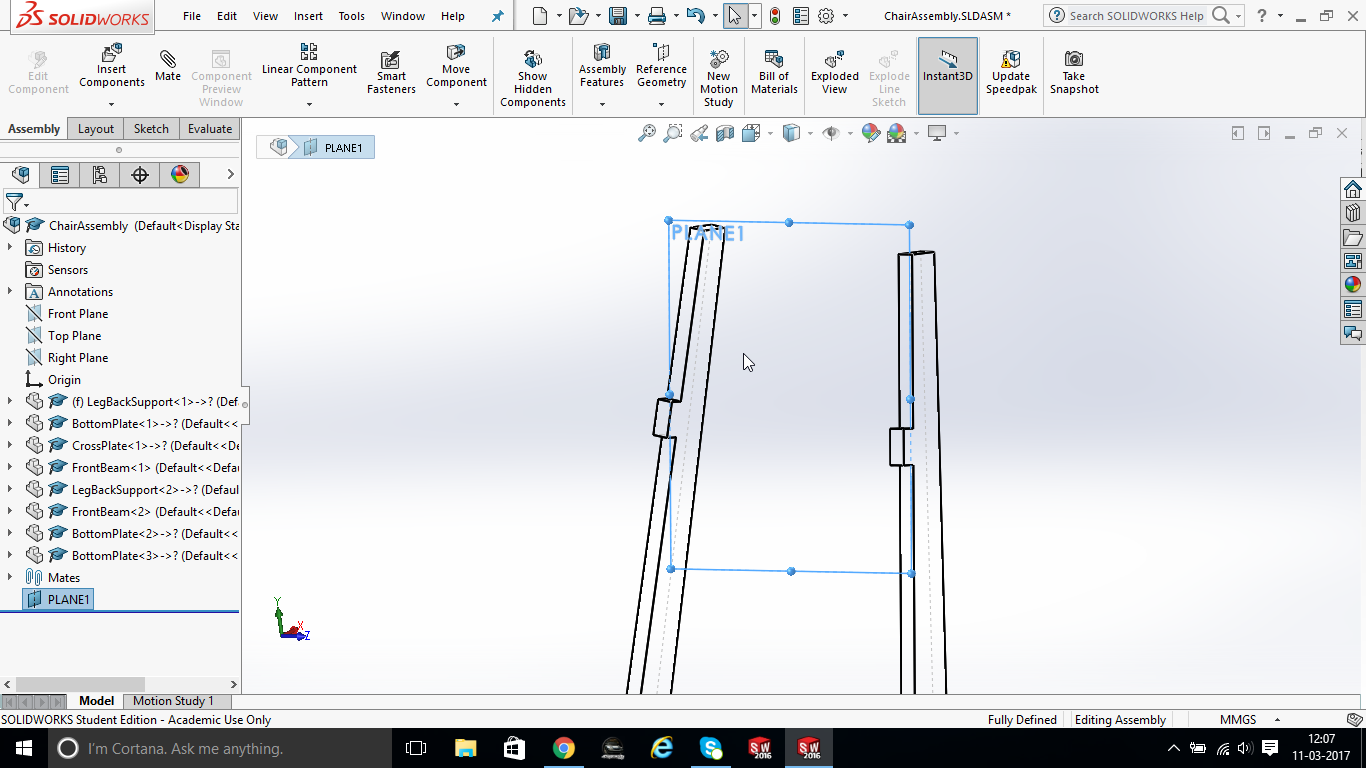
Creation of reference place
Back rest which is not exactly on single plane. But its drawn on reference plane derived from two lines as shown in image
Rough assembly model created
This assembly is created for visualisations. Then I have deleted this assembly keeping part models intact
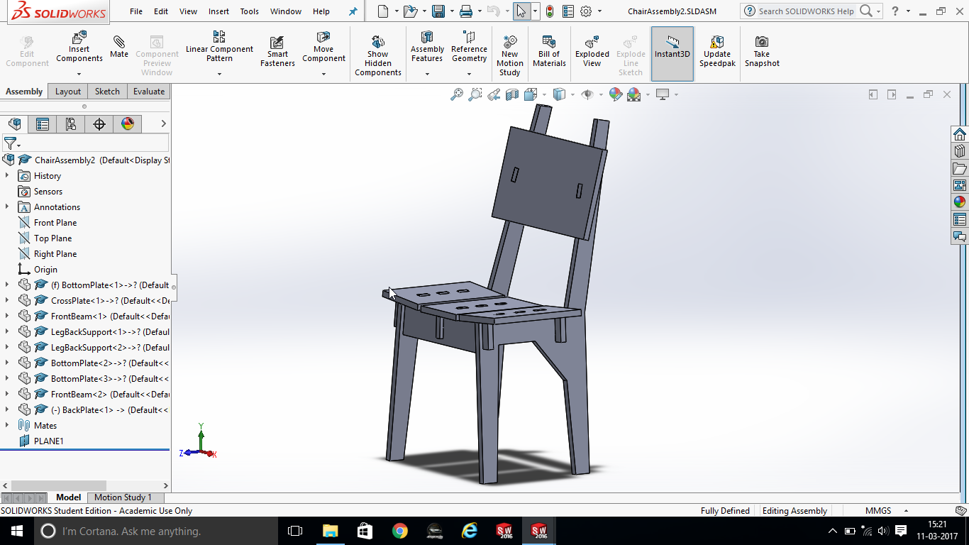
Why?
- Simply its clean and makes it more managable
- It groups mates. So you have less number of mates to manage
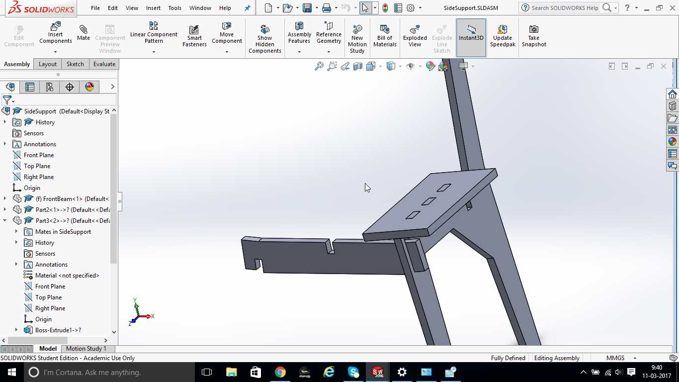
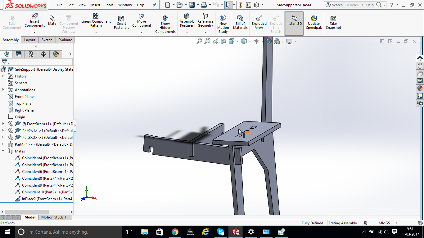
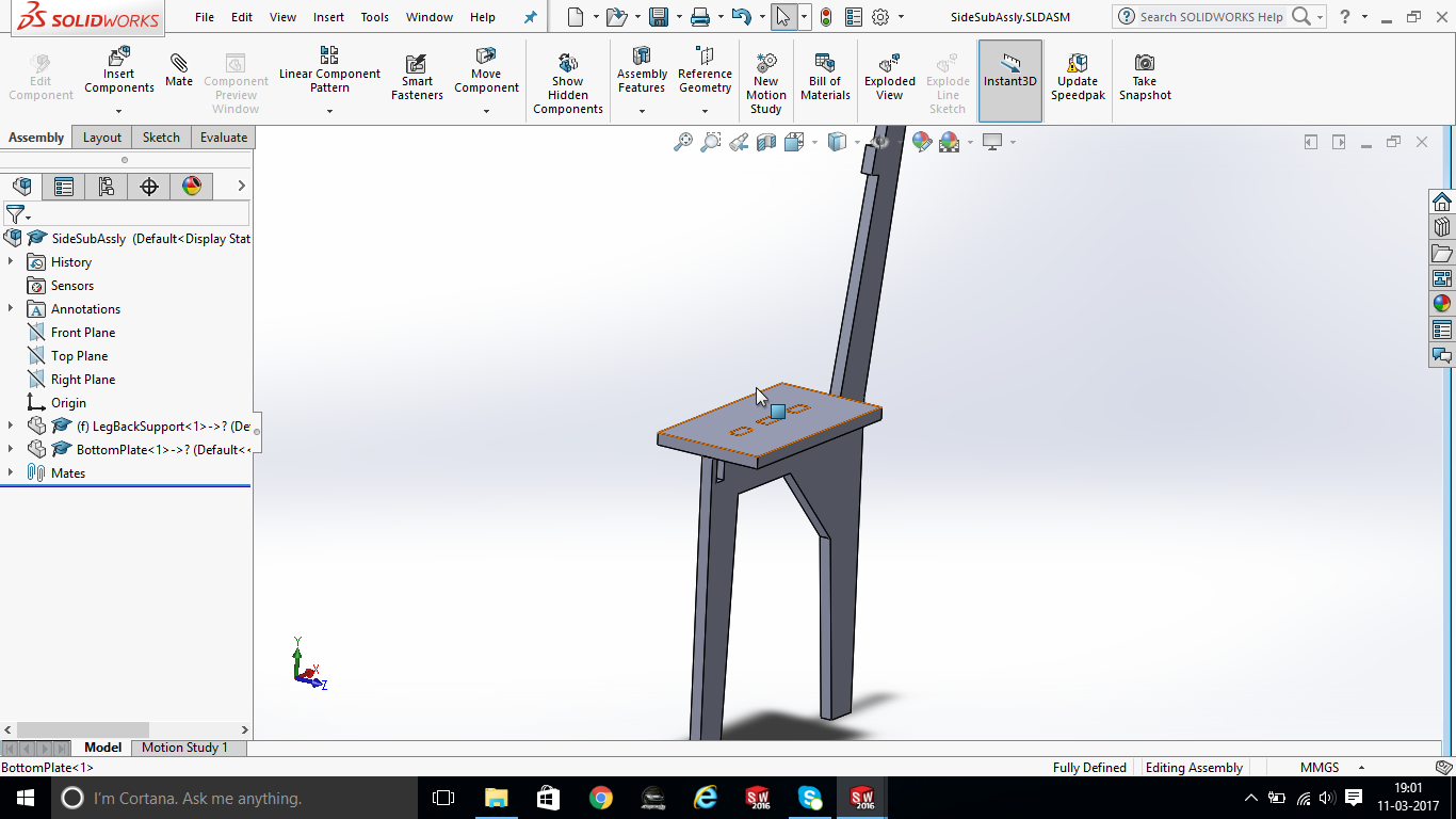
Side sub assembly
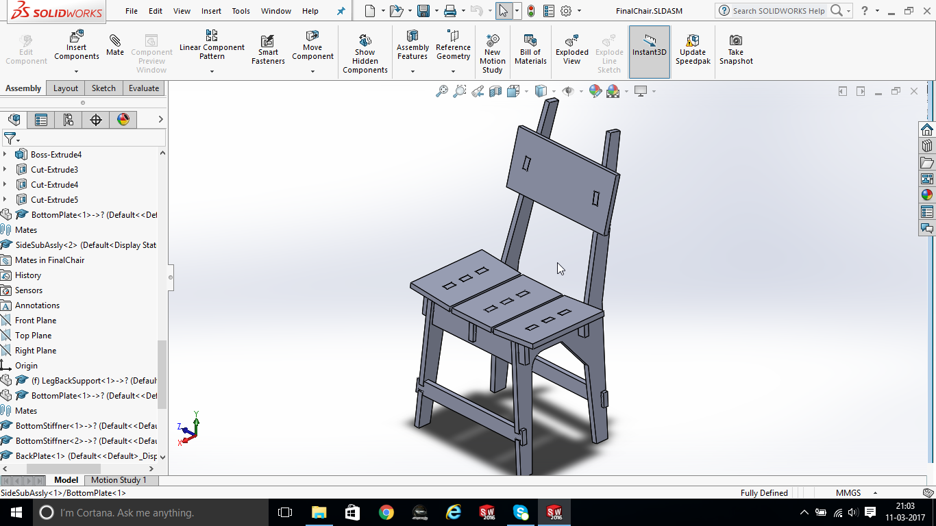
Final main assembly
Its a combination of three different assemblies and parts
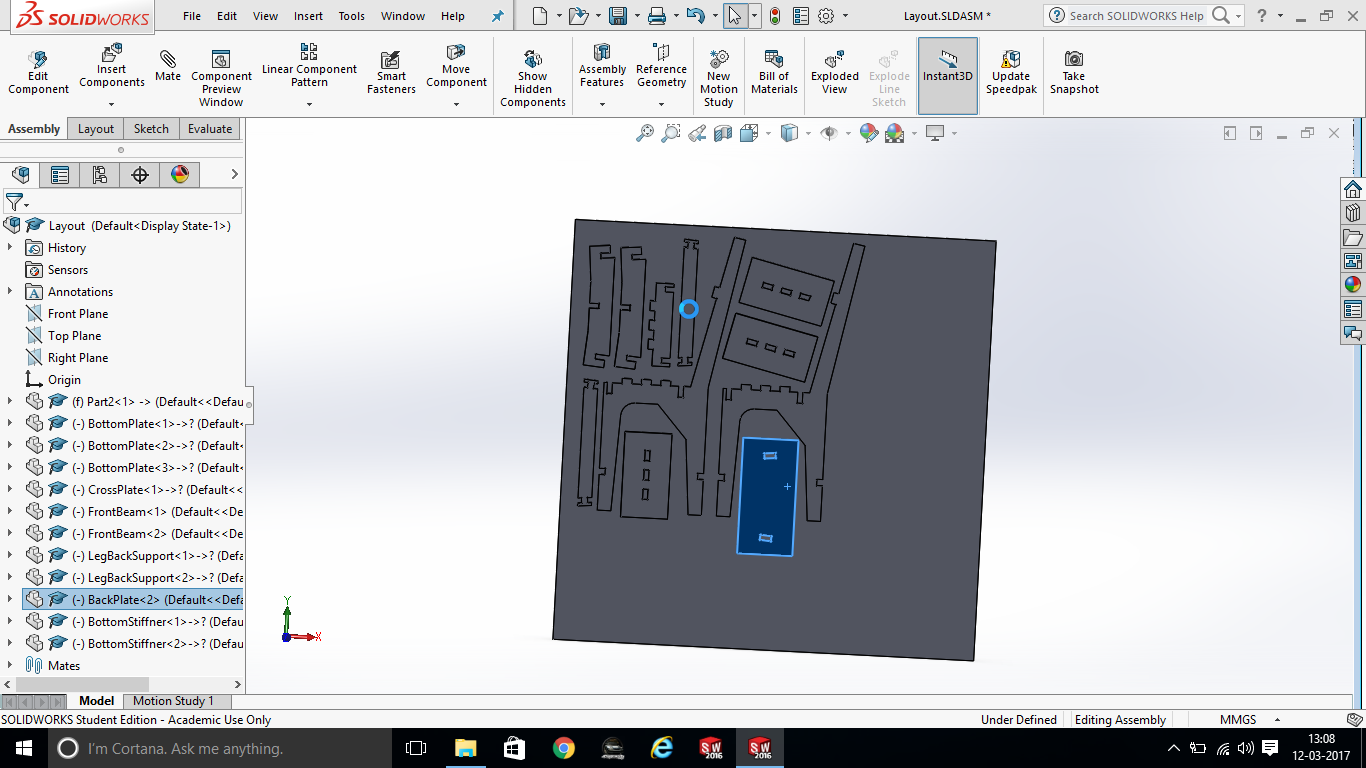
Layout assembly
Here a plate of 5 feet x 5 feet is created and component is placed. Using this method we can create layouts in solidworks assembly
Created drawing file and then exported to dxf
Direct exporting assembly model to dxf seems not available in solidworks. Whereas in part mode it is available. Hence I have created Drawing file (.SLDDRW) then exported it to dxf from drawing file
Files for download
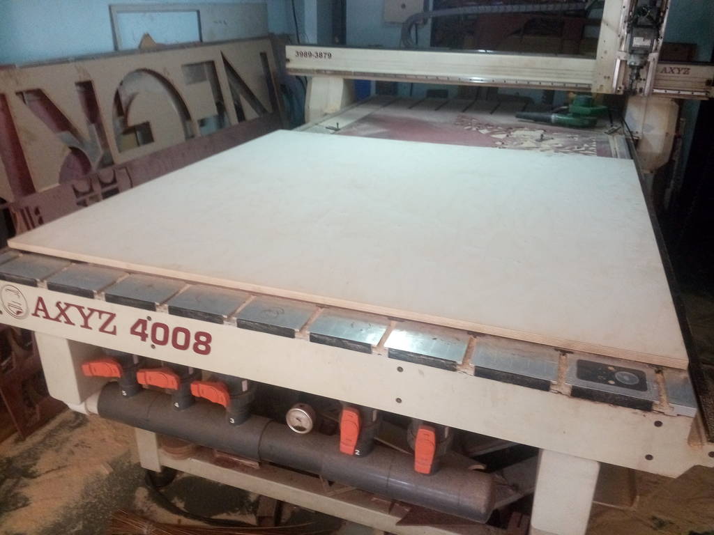
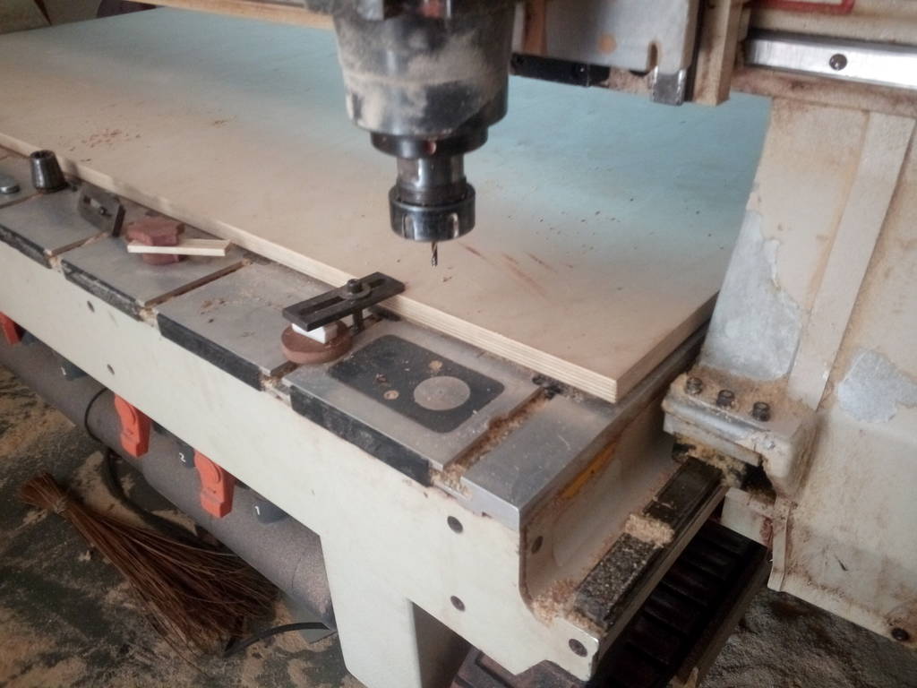
CNC router
Its canadian make router with following specifications
- Bed size : 5 feet x 8 feet
- Spindle power : 27 KW
- Spindle Max Speed : 25000 RPM
- Cam Software : Artcam
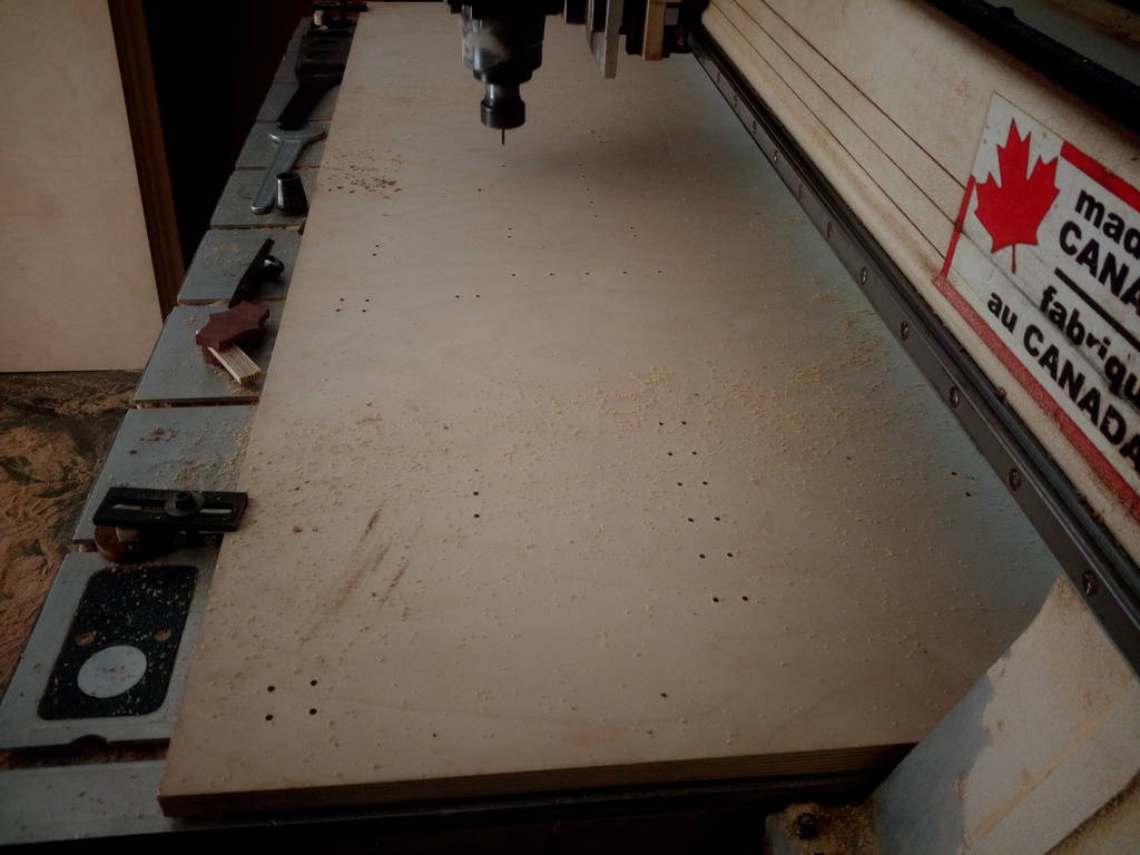
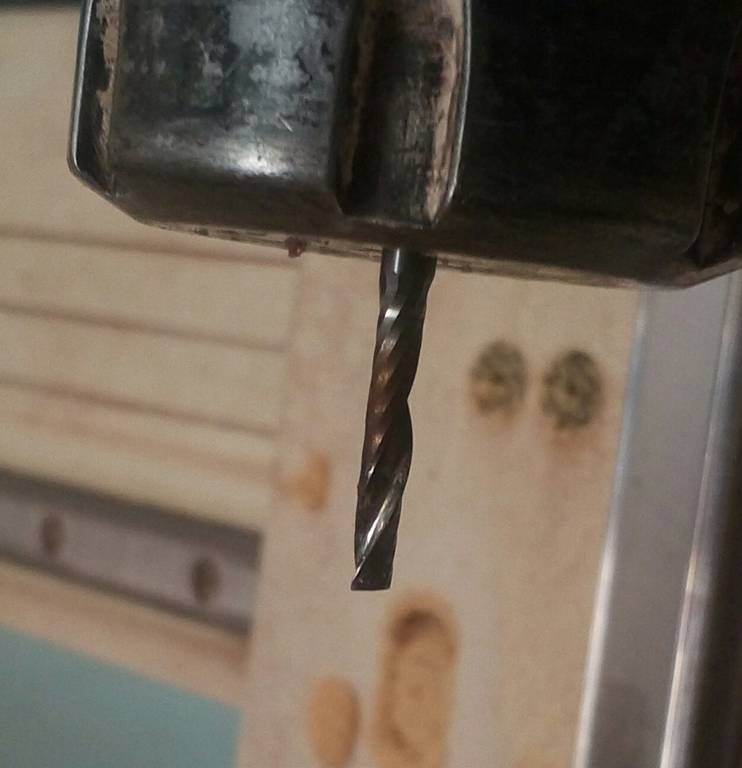
Collet chuck for holding Drill
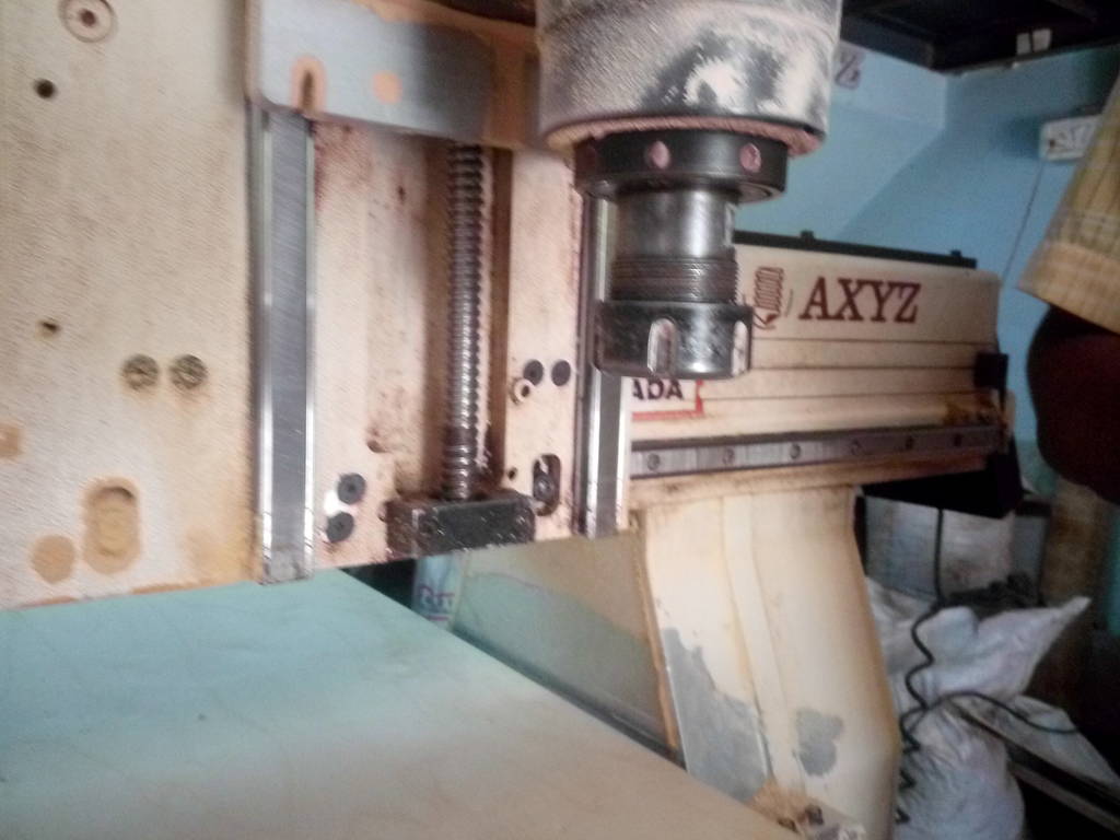
Drill bit loaded and ready to take Z zero reference
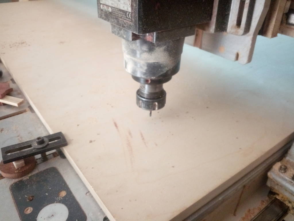
Machine moves down and takes reference
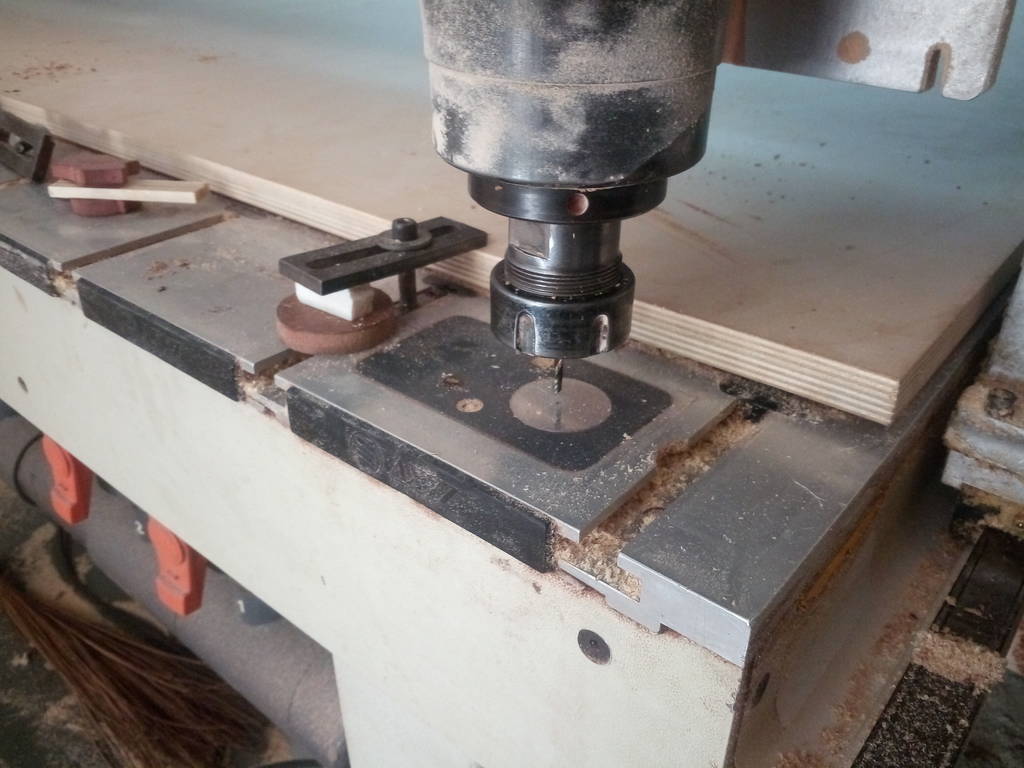
Measure start height. It is the maximum height from where cutting will start
Using artcam for creating tool path for CNC router
Following are settings for CNC program
- Spindle RPM : 18000
- Depth of cut in single path : 9.5 mm
- Feed rate : 2500 mm/min
- Cutter diameter : 6 mm (Side cutting endmill)
- Drill diameter : 4 mm
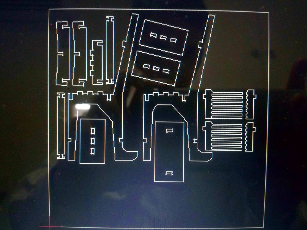
Artcam screenshot
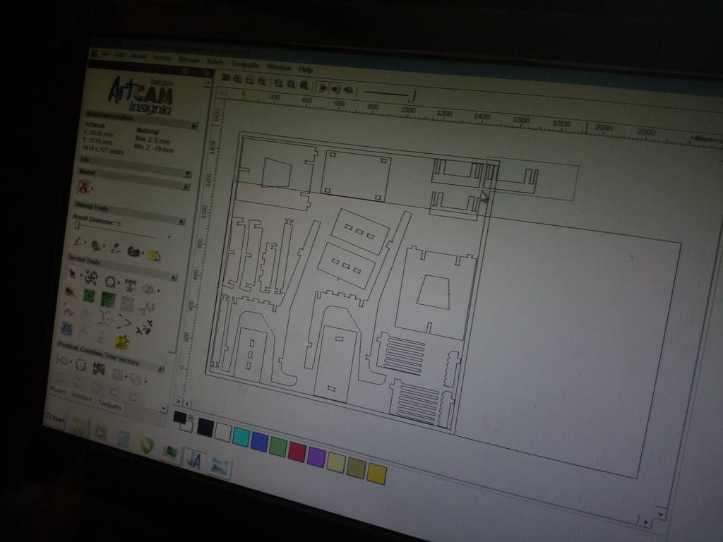
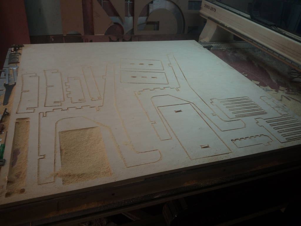
Drilling pass done which has created relief drills wherever required
Endmill dia 6 mm
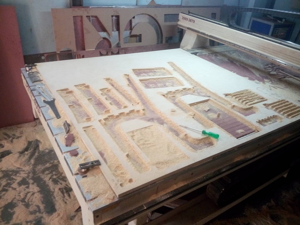
Cutting completed
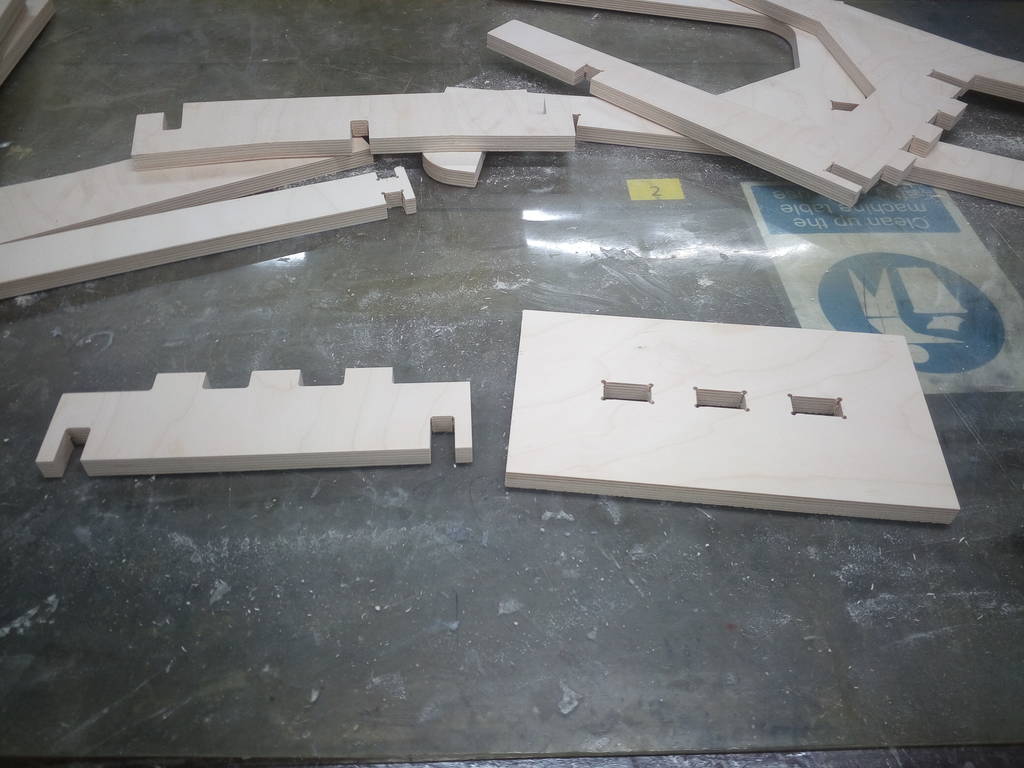
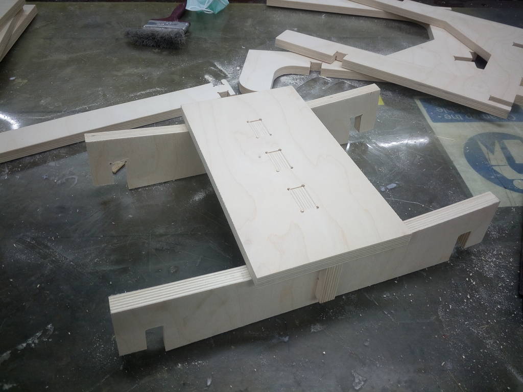
Components removed for doing assembly
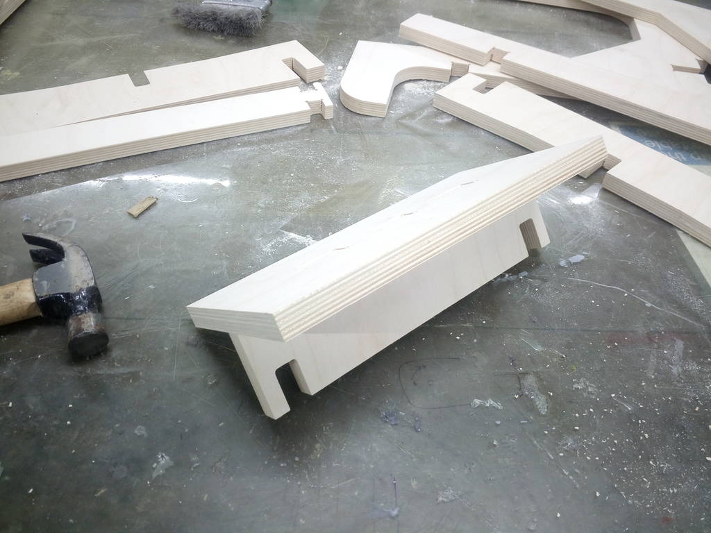
Assembly sequence
All of the above cut components are assembled in a sequence as shwon below
Following correct assembly sequence and planning for it at design stage is very crucial. This will prevent us from designing something which we cannot assemble
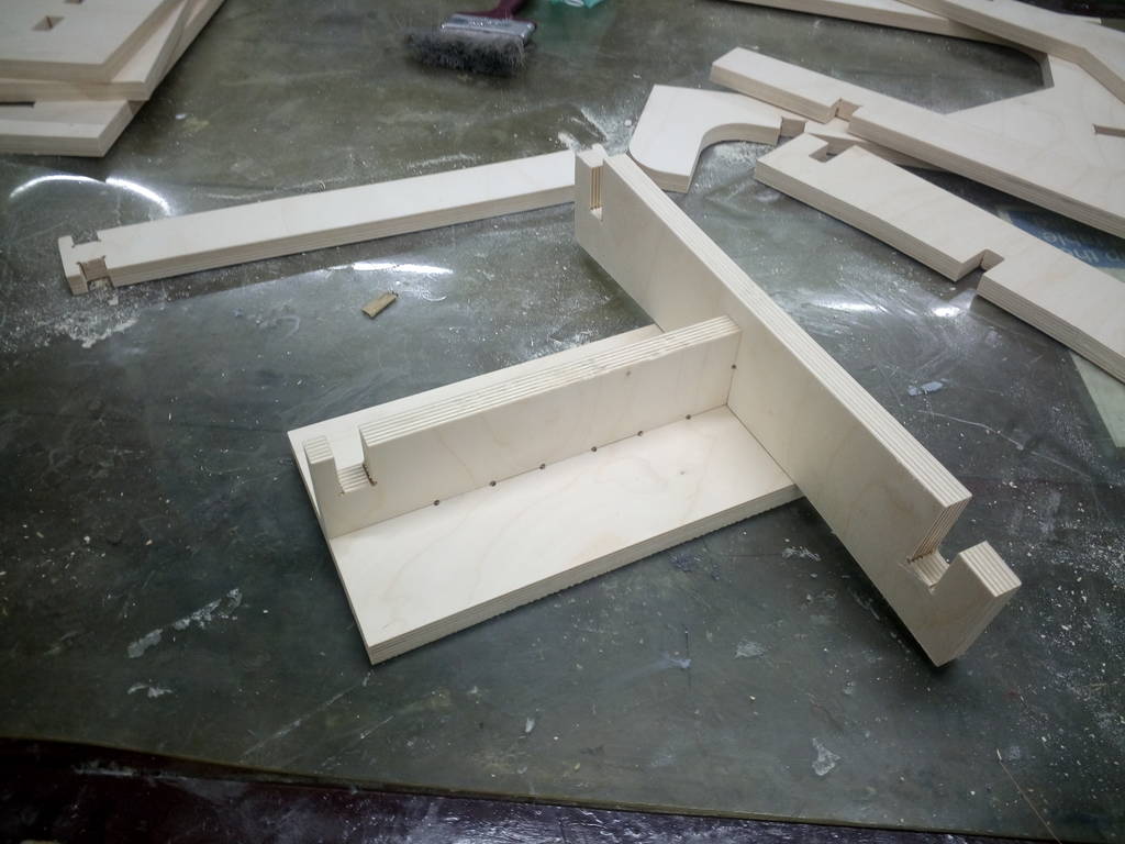
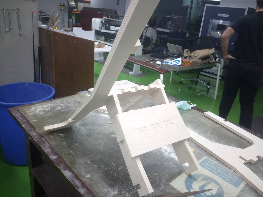
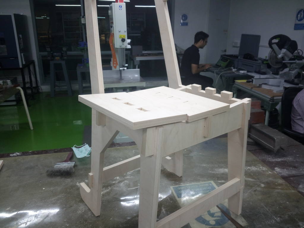
Creating middle assembly
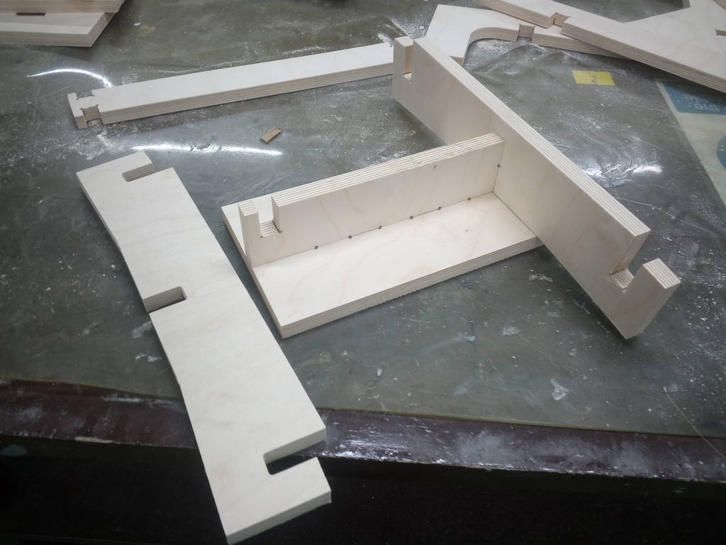
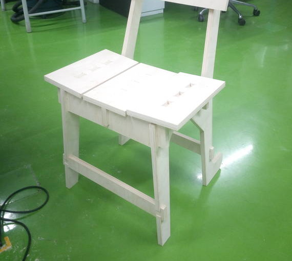
Finally
