Designing model to be moulded
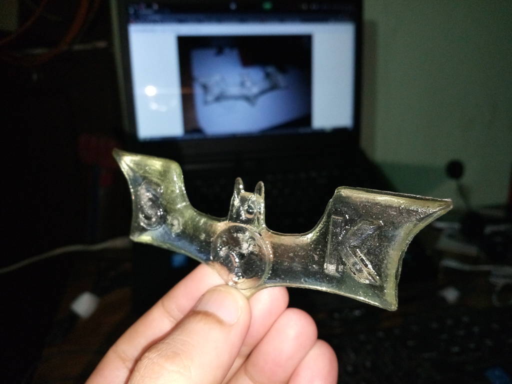
For this week I have decided to make a batman symbol casting as referred to this in image.

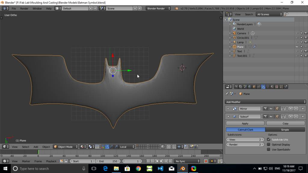
Batman Symbol Modelled
Started in Blender
I have started with Blender 2.78
Blender cheatsheet
Blender comes with a very useful shortcut keys which makes you model very fast. This is a best chearsheet which I can find on net
https://i.imgur.com/E42hJ7I.jpg
https://i.imgur.com/E42hJ7I.jpg
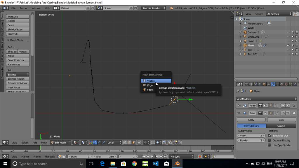
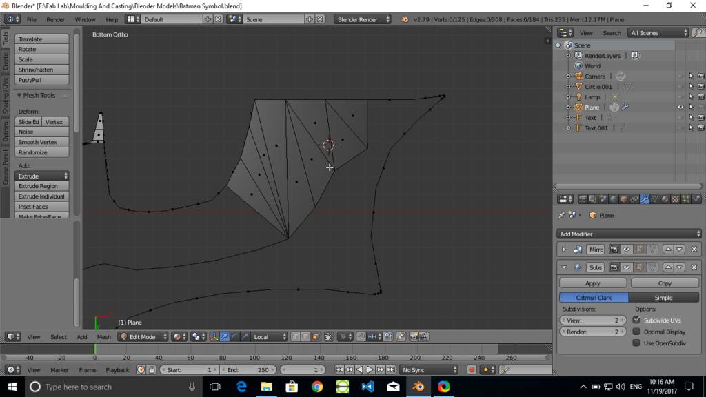
Designing batman symbol in blender
Use Numpad 7 Key for top view
Numpad 5 toggles between perspective and ortho mode.
Press numpad 5 to be in ortho mode.
Insert line and press Tab to enter in edit mode.
Press ctrl tab and select vertex select mode.
Select vertex and press E to extrude.
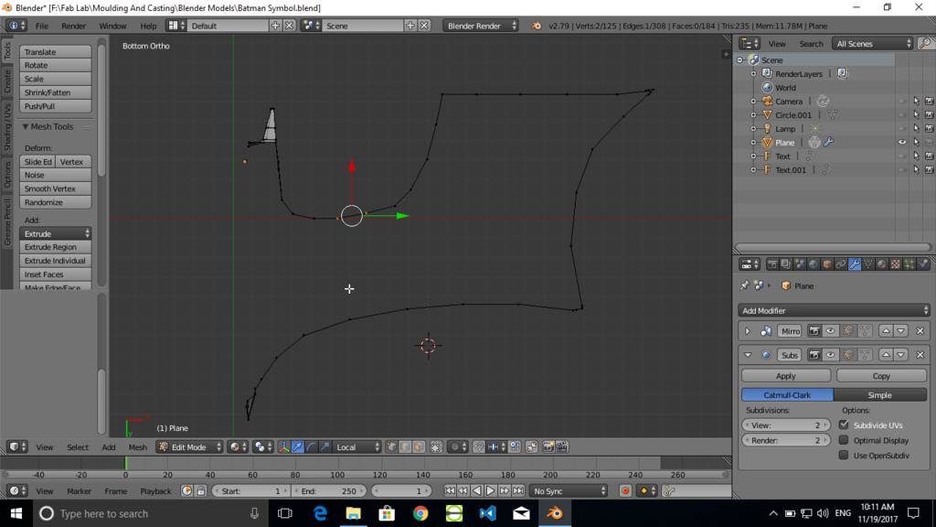
Make a shape as required. as shown in screenshot
Press numpad 5 to be in ortho mode.
Insert line and press Tab to enter in edit mode.
Press ctrl tab and select vertex select mode.
Select vertex and press E to extrude.
Make a shape as required. as shown in screenshot
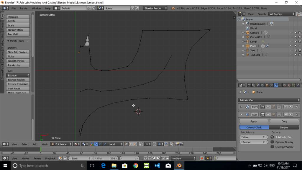
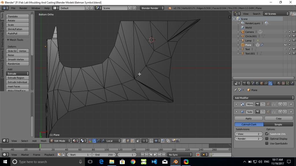
Extrude vertex to form a required Shape
Add more points at curve and less points at straignt edge.
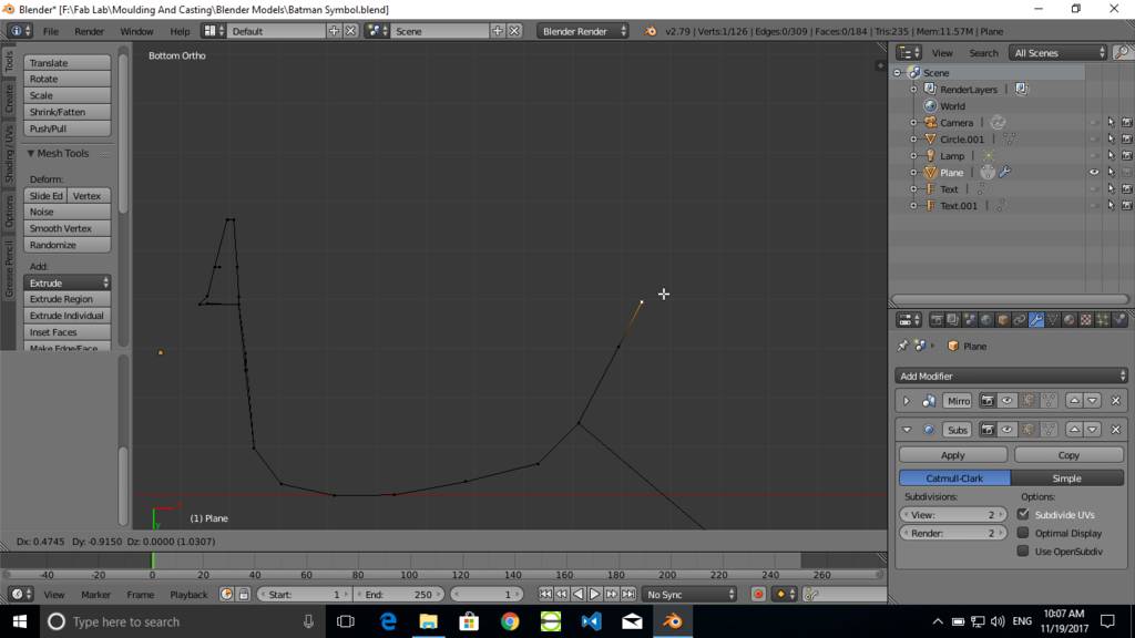
Draw complete outline as required
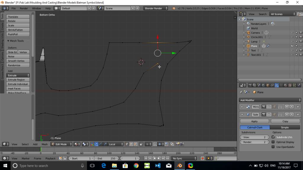
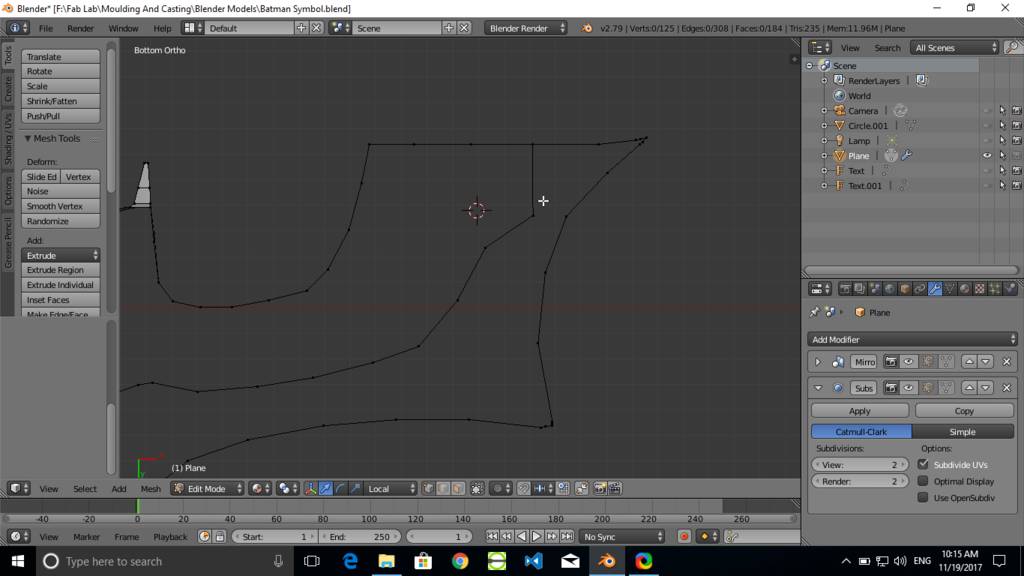
Add another line geometry
Add another line at the middle which is used for generating required geometry. This line is then raised up to make emboss effect
Join two points
Select two vertice points and press F to join those points by line.
Created line joining two vertrice points
Create faces
Select two Edges and press F to create a face joining two Edges
Create remainaing faces to form a geometry
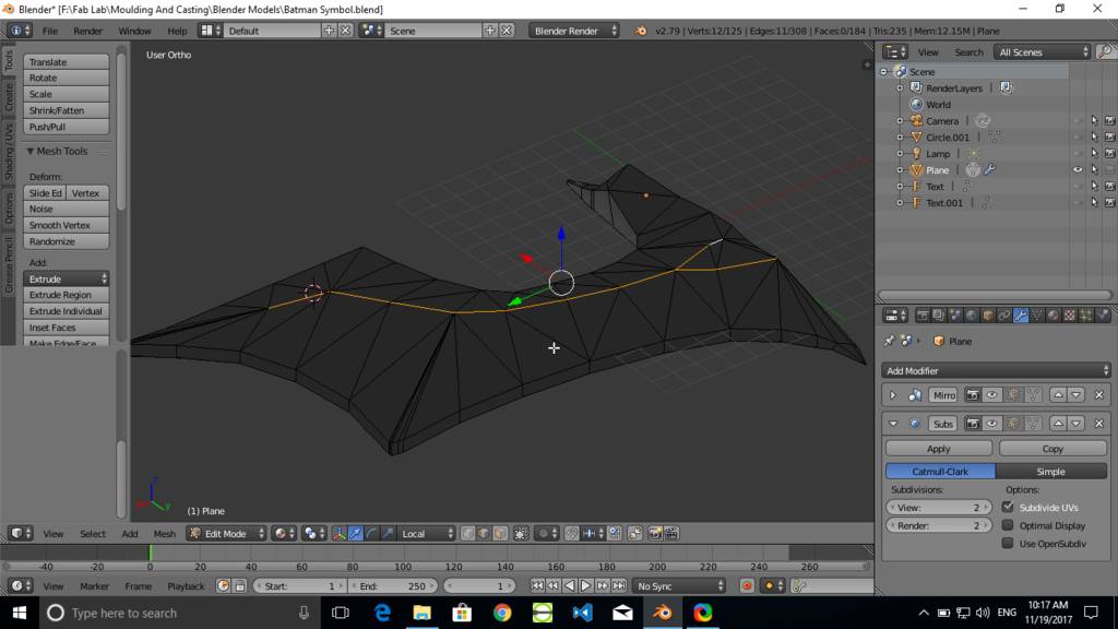
Create thickess to model
Select a set of edges and press G to grab and move edges. Press Z to constraint movement to Z axis only.
Manually move edges up to form required thickness and geometry
Manually move edges up to form required thickness and geometry
Use modifiers
- Add mirror modifier to create mirrored geometry
- Add subsurf modifier to create smooth surface of geometry
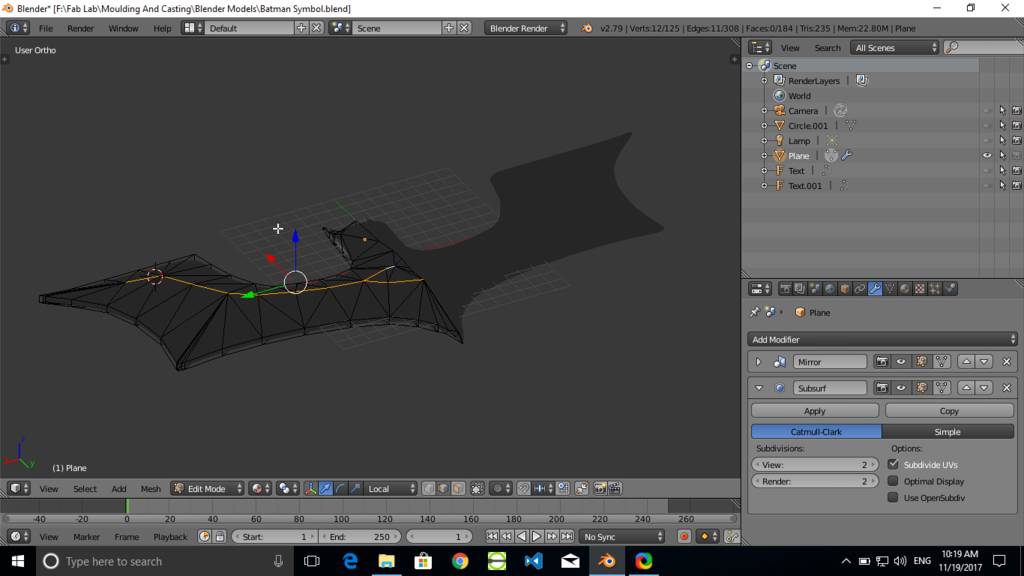
Basic completed model for batman symbol
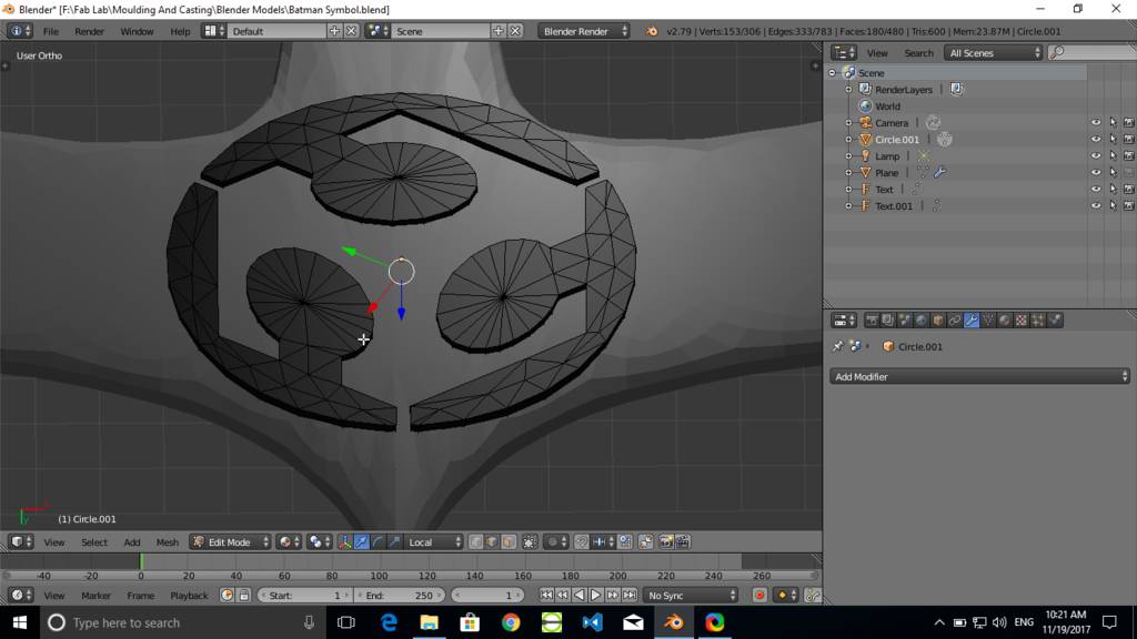
Created fabacademy sumbol
Using same technique where I had extruded vertrices and joined edges with faces. I have created this symbol. Selected all vertrices and extruded to form a thickness to it.
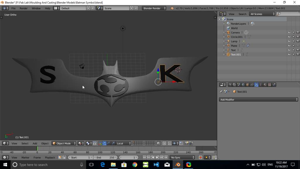
Creating letters
Created characters S and K using text tool of blender
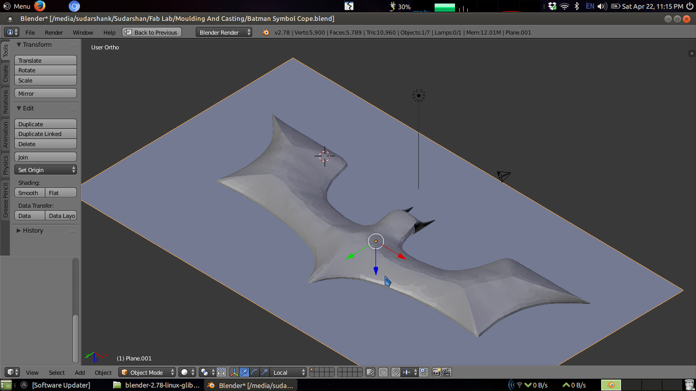
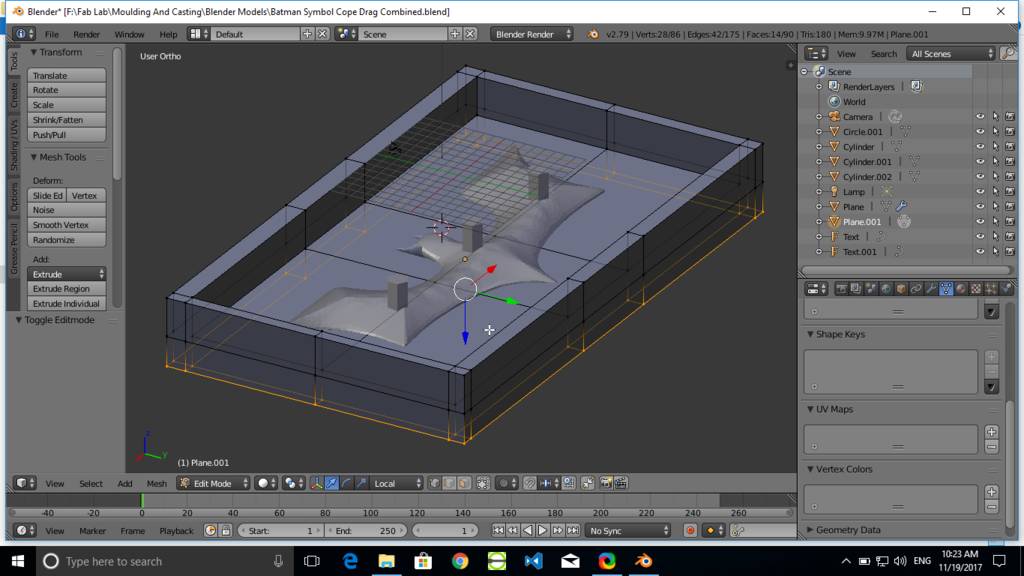
Crerated parting plane
Created parting plane at the center of model. SO as to create cope and drag can be created
Form a rectangular mould cavity
Risers are also created. Same are used for pouring of casting material
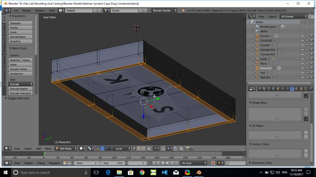
At the bottom it looks like this
Bottm part is a cope and top part is a drag. At this point I had made another copy of this file and removed all unnecessary geometries and formed cope and drag.
Final Batman symbol designed
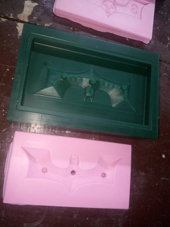
Bottom Part Mould
Top Part Mould
Preparing Mould for Mould using milling operation
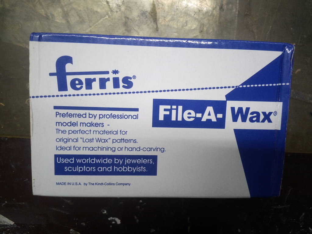
Freeis Wax to be milled
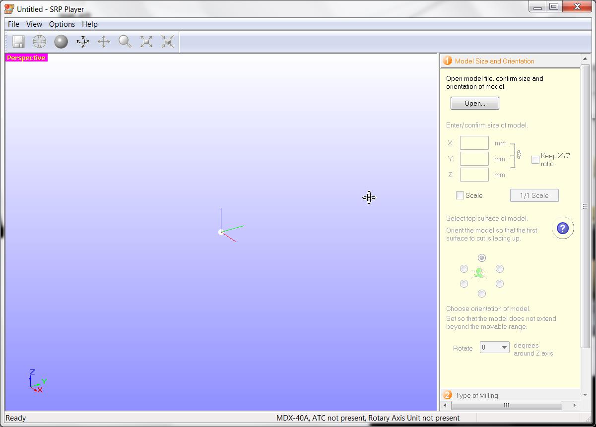
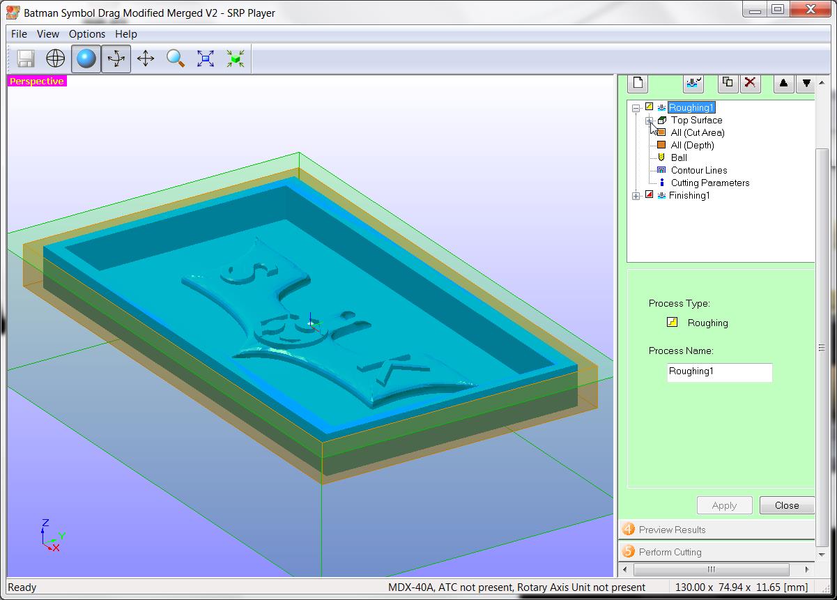
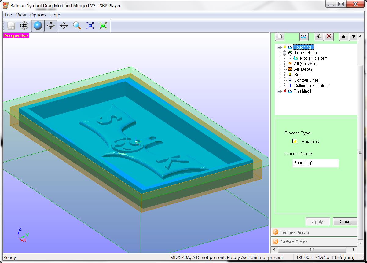
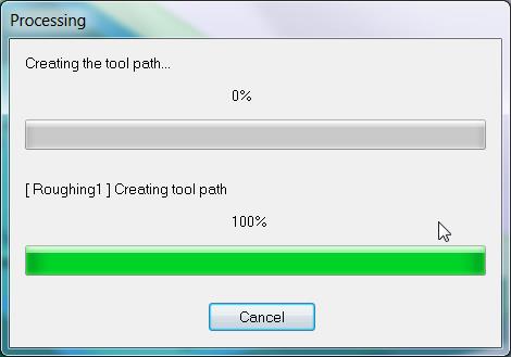
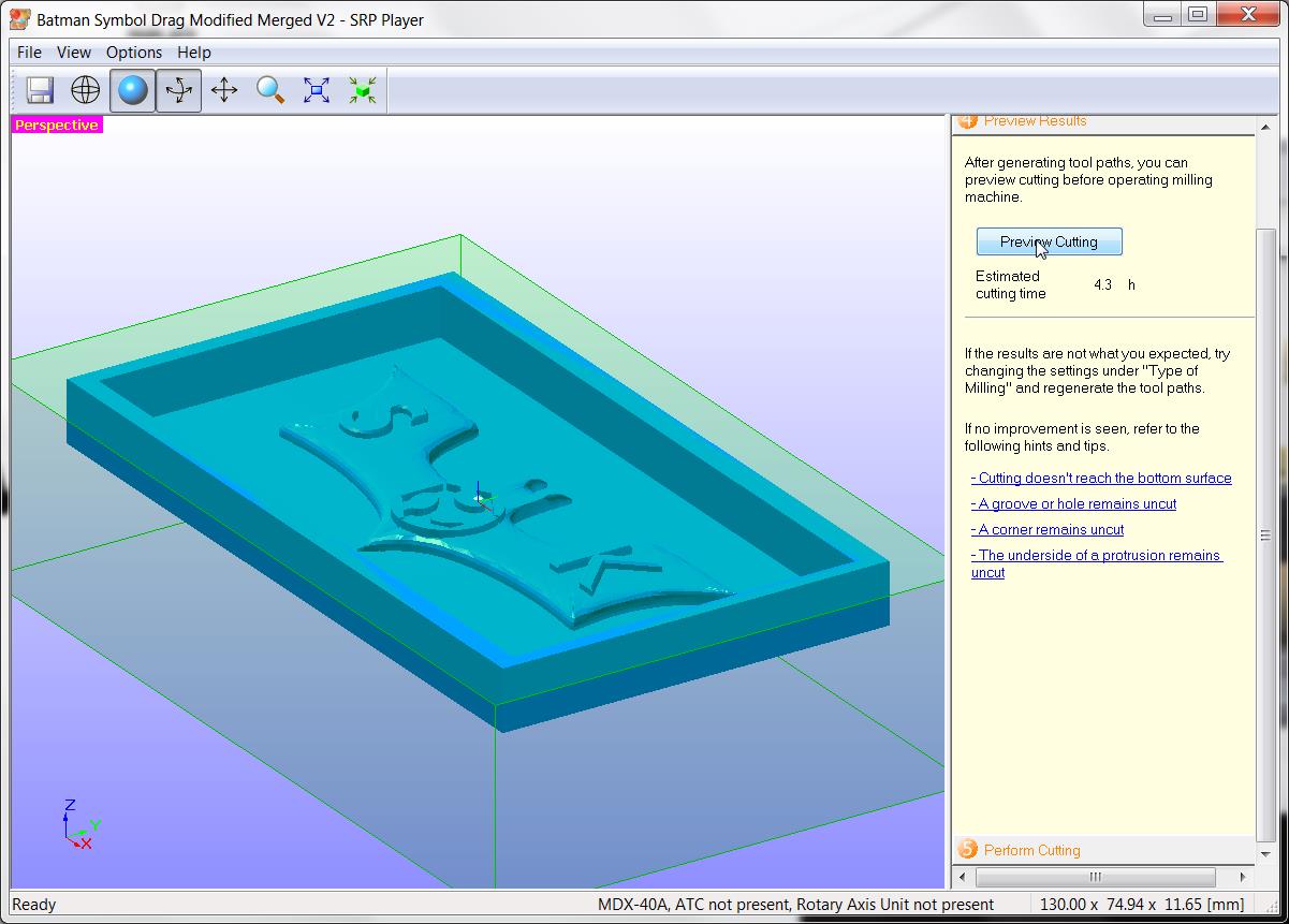
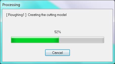
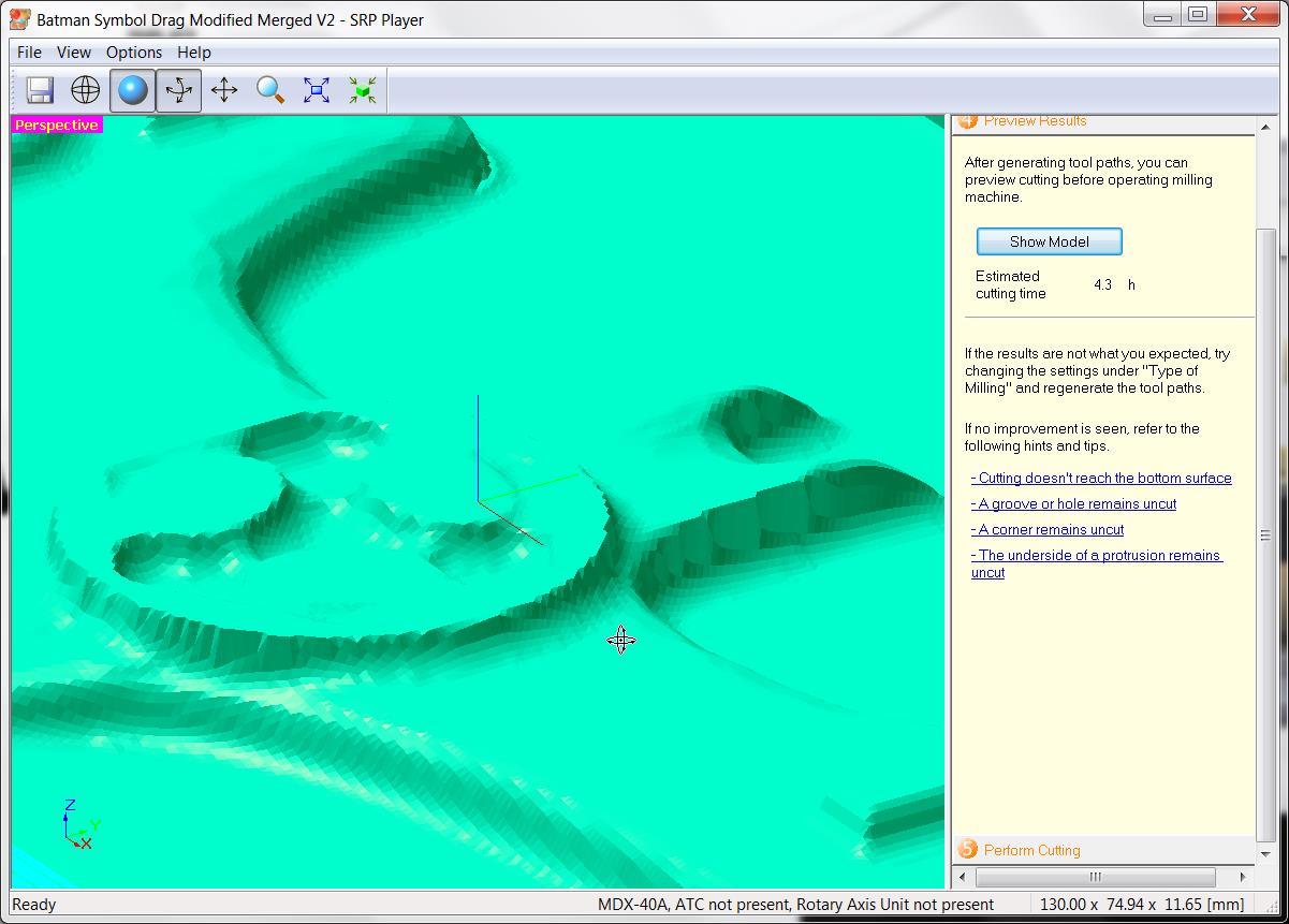
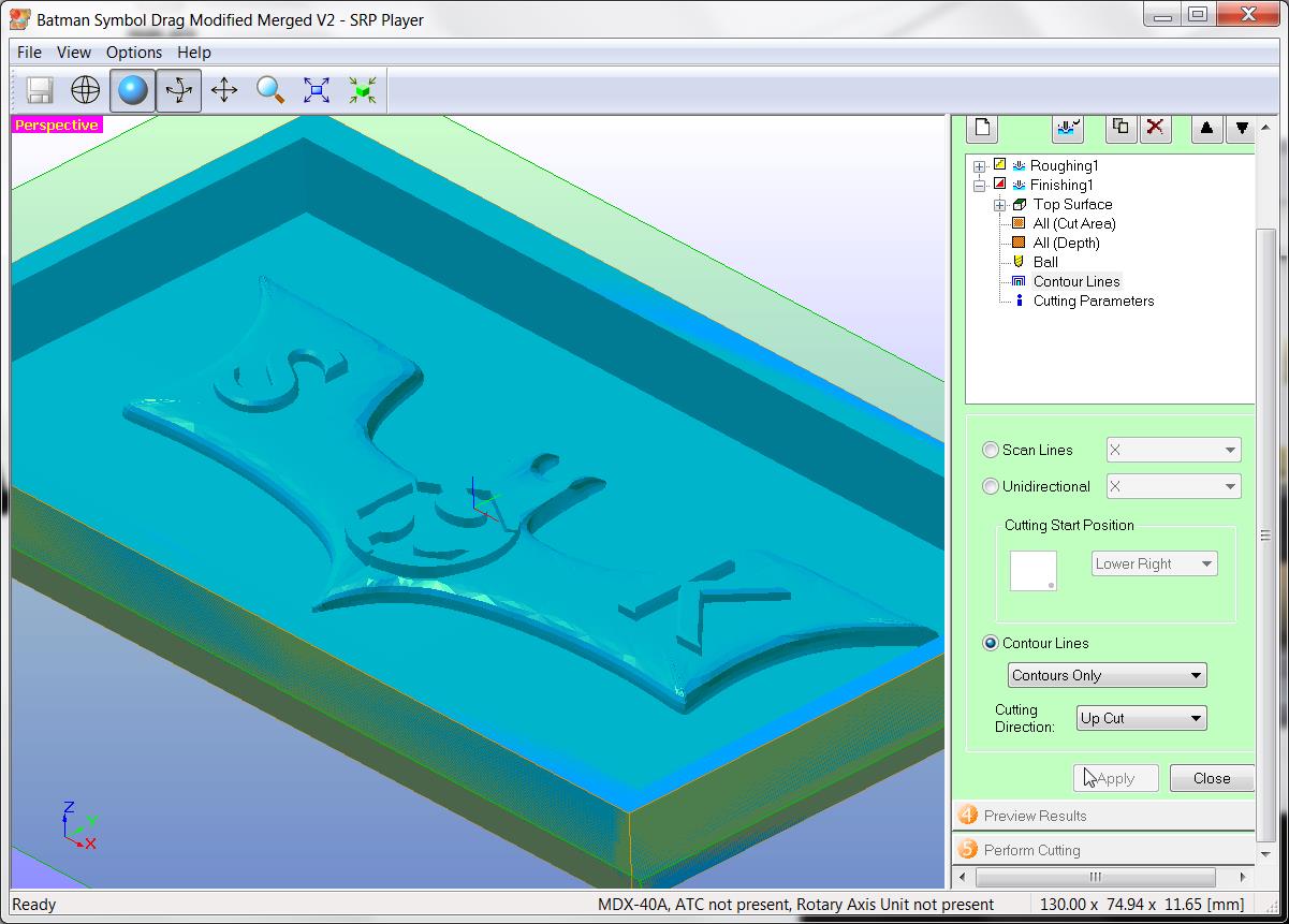
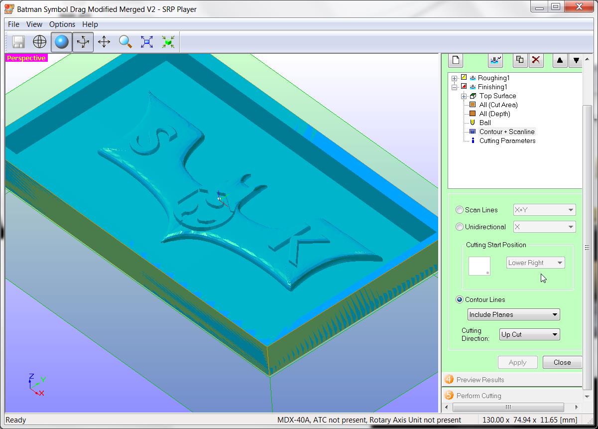
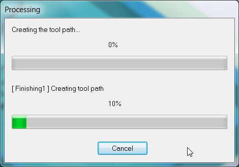
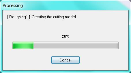
Creating toolpath for milling using SRP Player (Subtractive Rapid Prototyping)
Using SRP player software which comes with MDX-40 milling machine
Below is a screensequence of how toolpath is generated using SRP Player

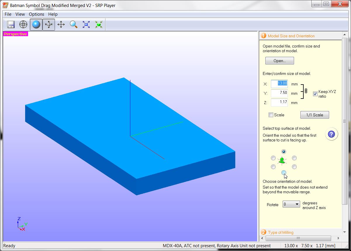
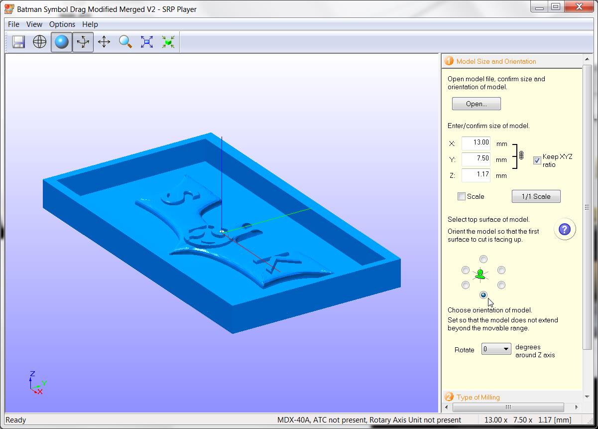
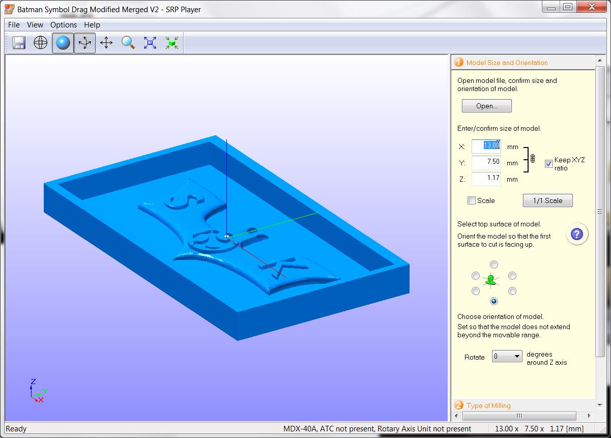
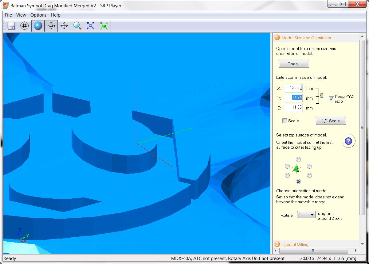


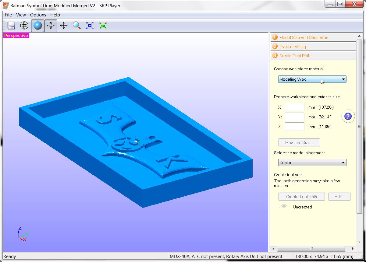
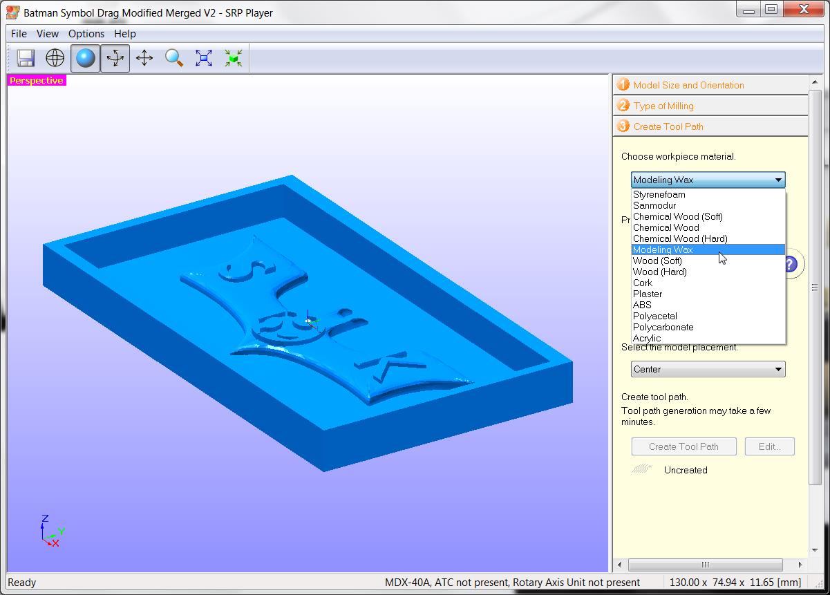


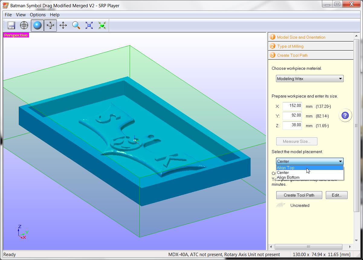
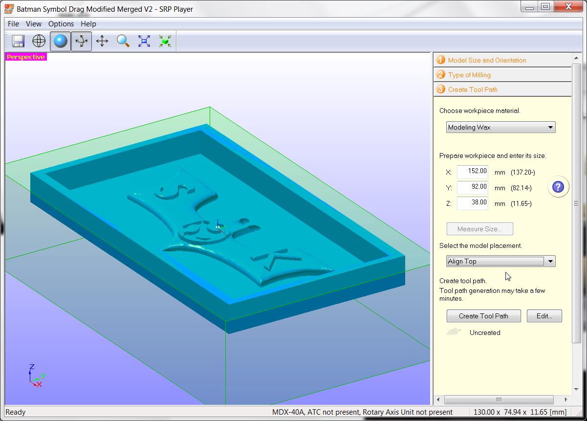


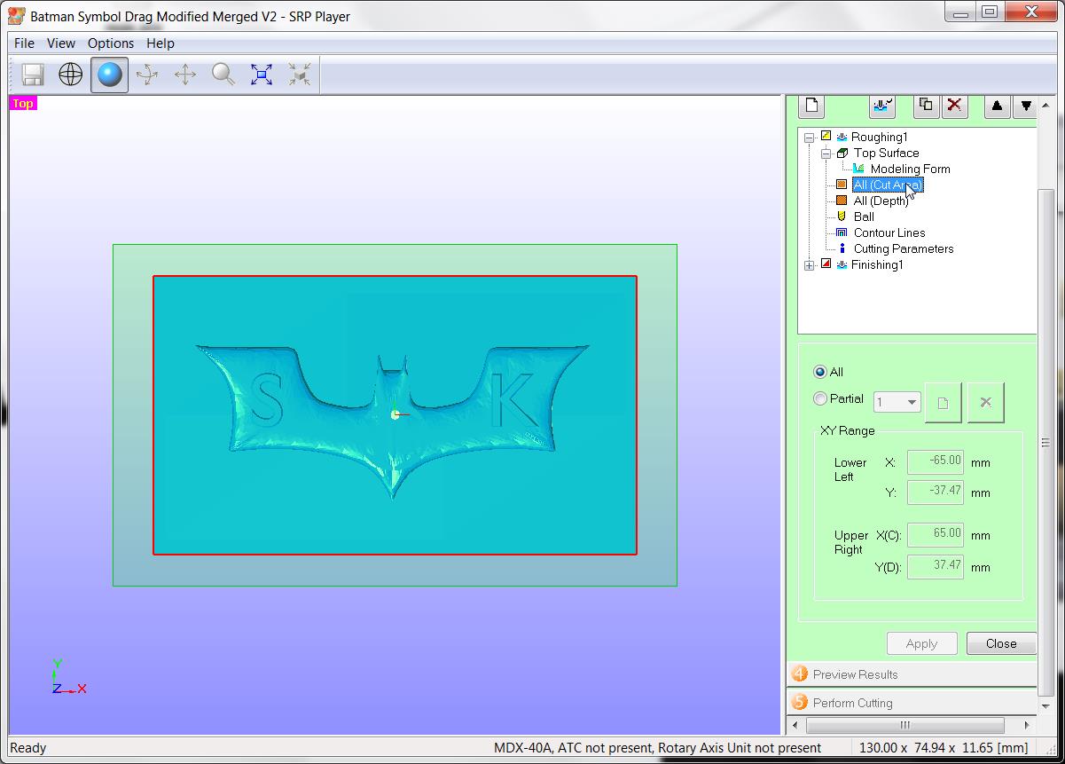
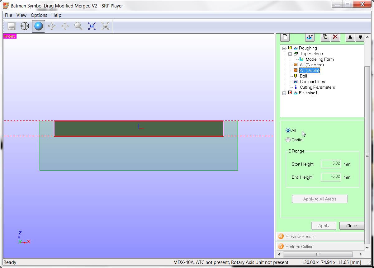
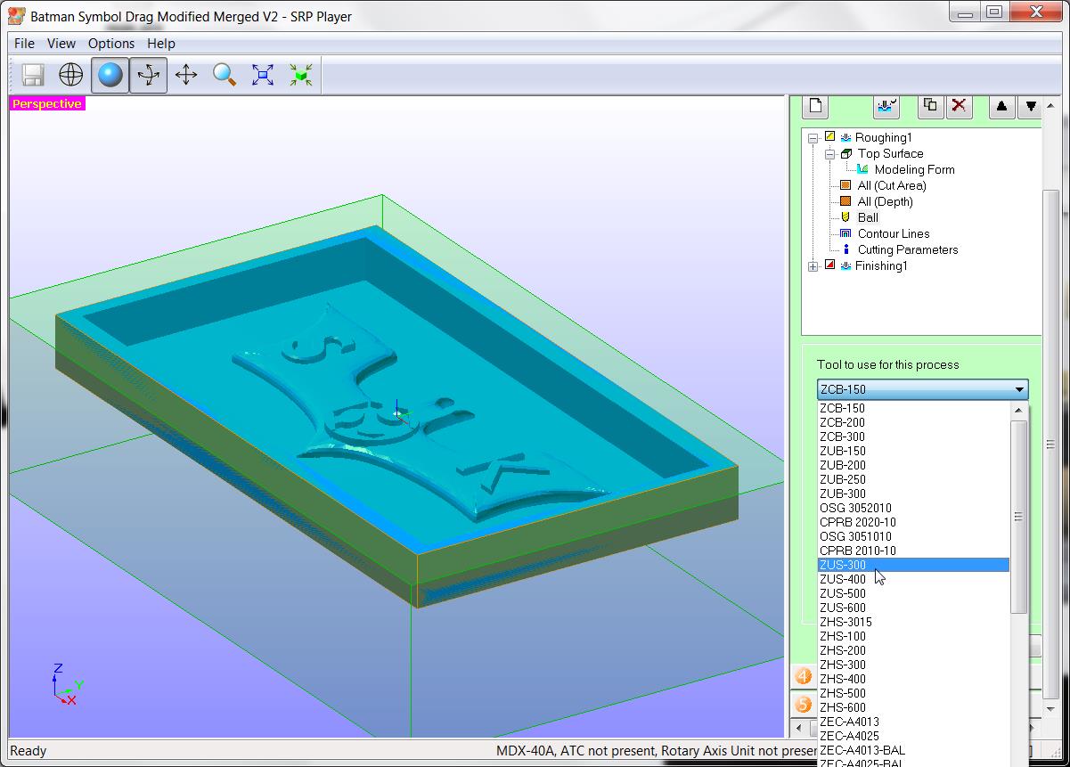
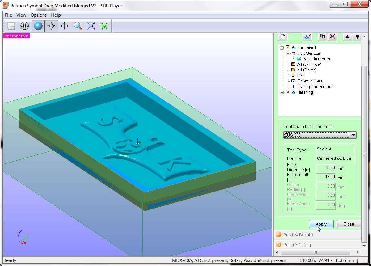


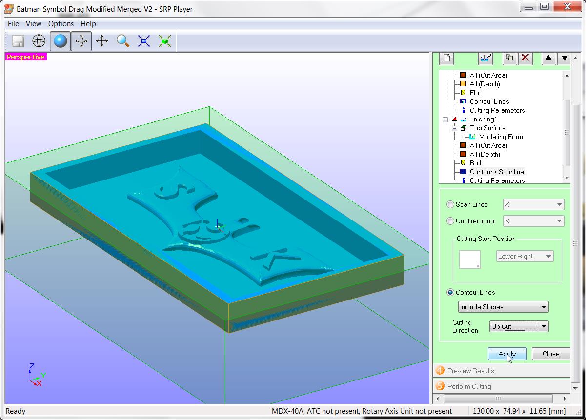


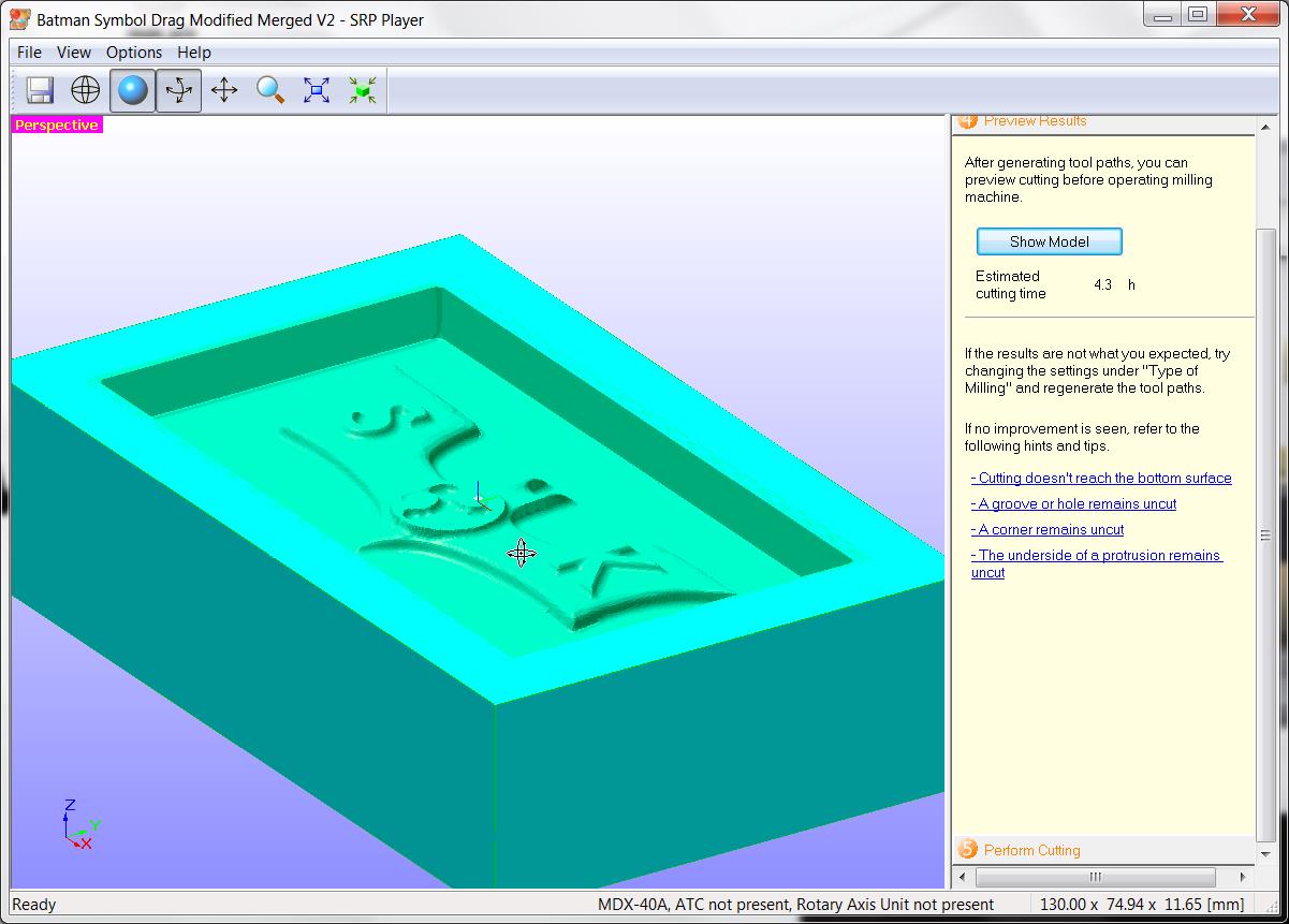
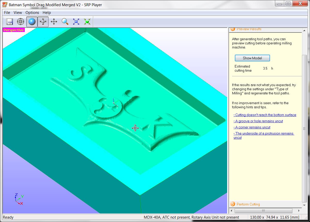


Setting of SRP player
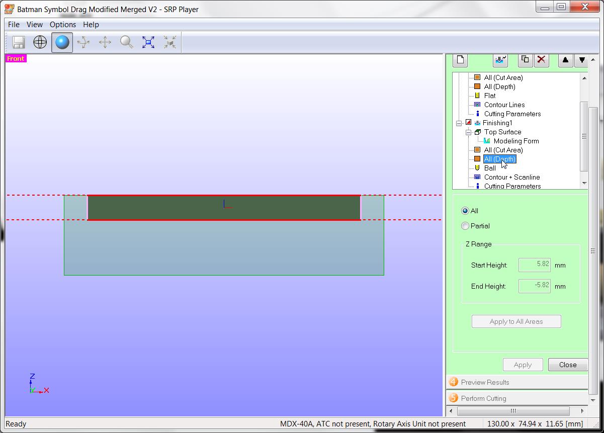
- Size of Model : X = 130.00 mm, Y = 75 mm, Z = 11.6 mm
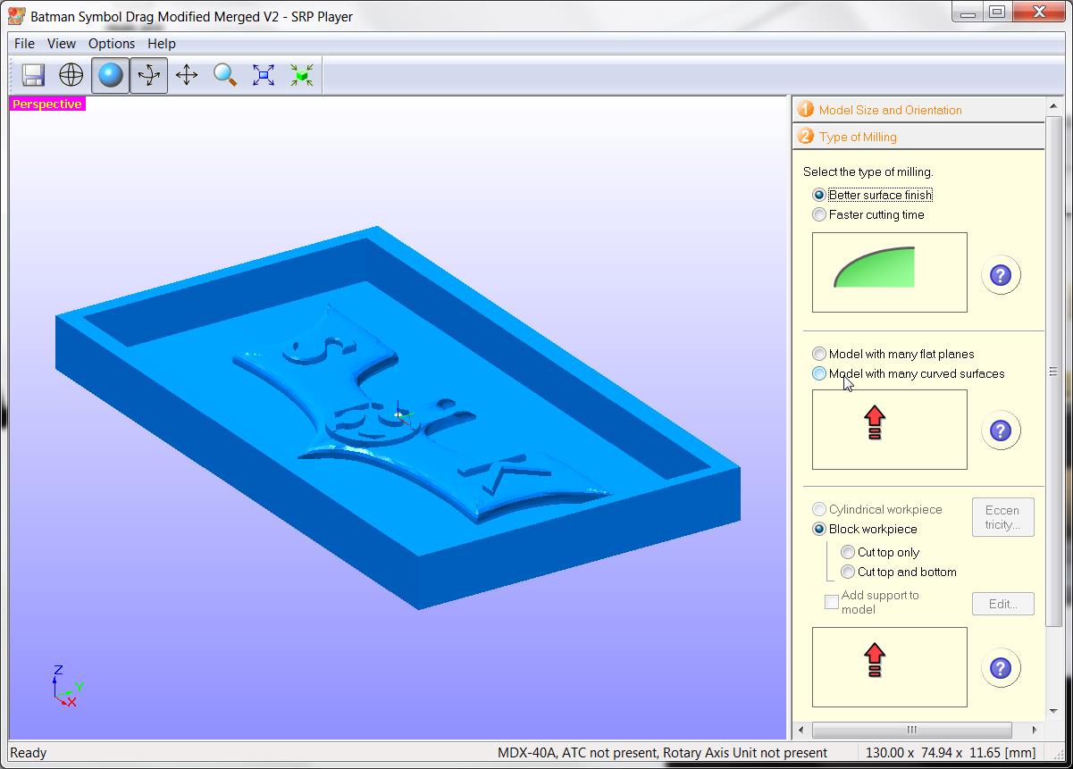
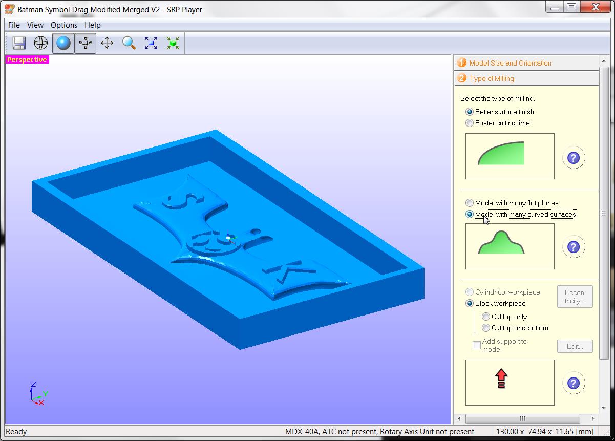
- Type of milling : Selecting for better surface finish
- Workpiece : Block workpiece
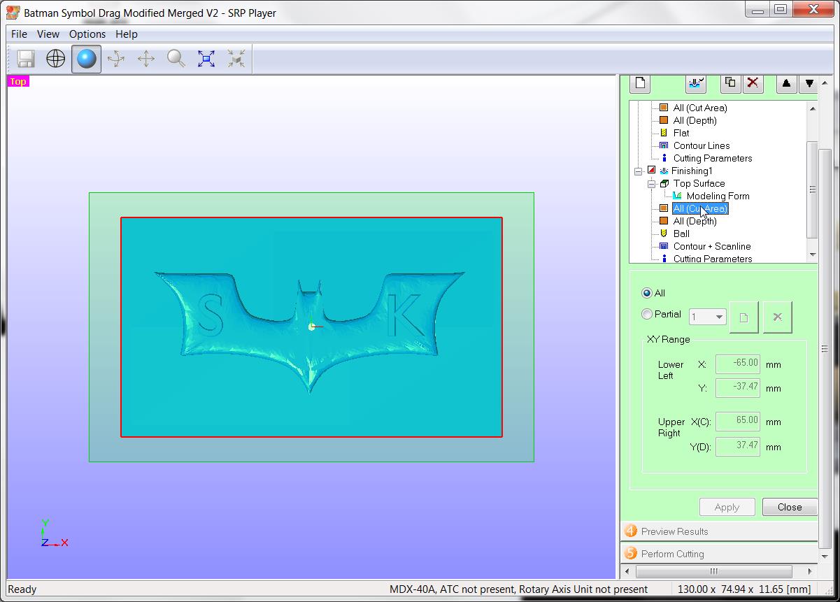
- Selected model with many curved surfaces
- Workpiece material : Moulding wax, Size X = 152 mm, Y = 92 mm, Z = 38 mm
- Model placement : Align top
- Removed all margins
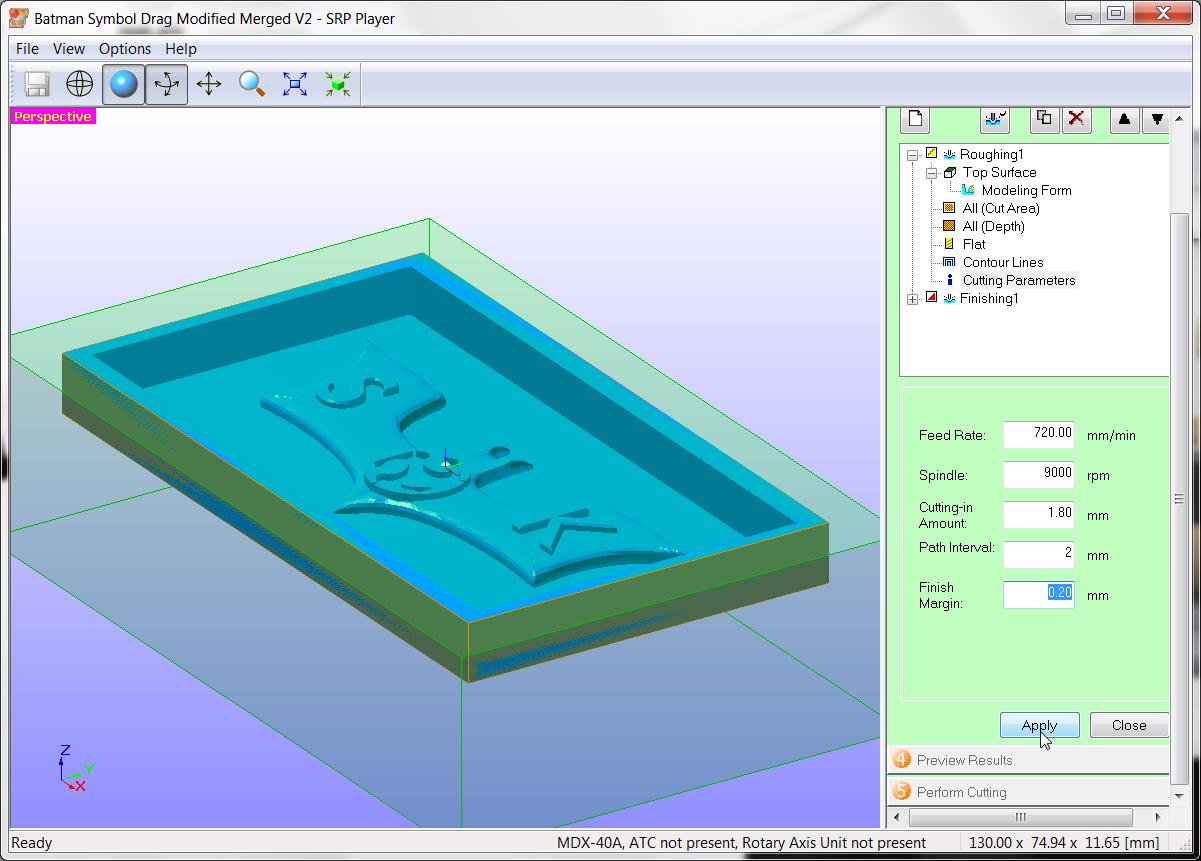
- Roughing Cutter : Straight 3 mm dia cutter
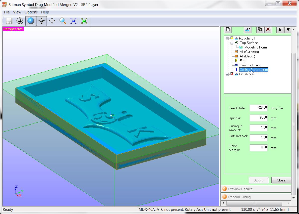
- Roughing Feed : 720 mm/min
- Spindle speed for roughing : 9000 RPM
- Cutting in amount / Depth of cut : 1.8 mm
- Path Interval / Overlap : 2 mm
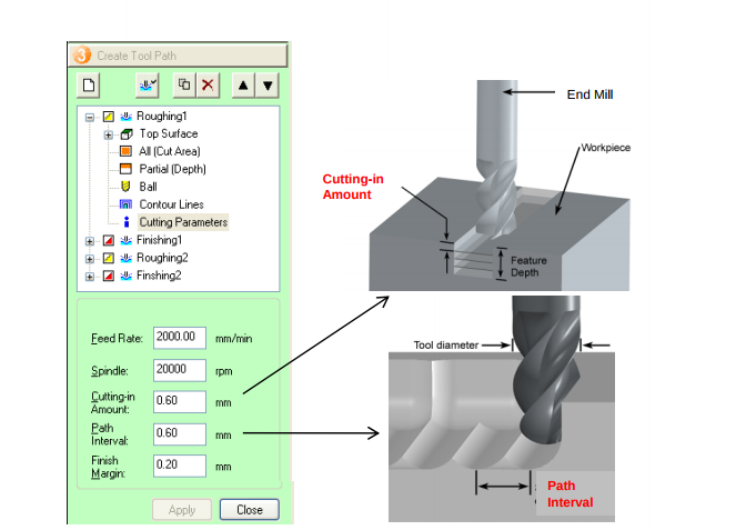
Reference : Roland Manual. Download PDF from here
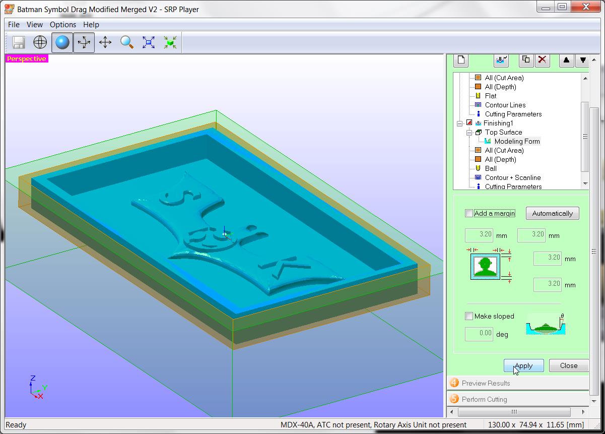
- Finish margin : 0.20 mm
- Finishing cutter : Ball nose cutter of dia 3 mm
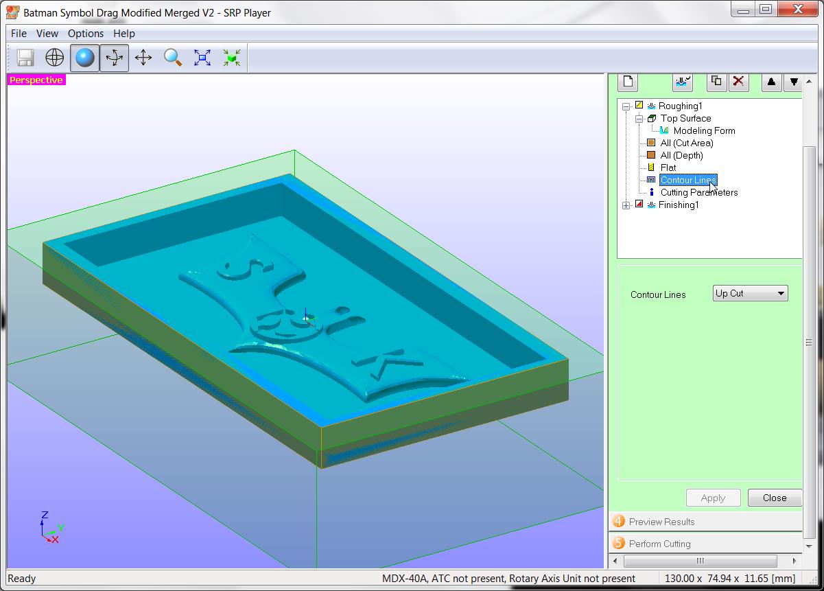
- Finishing Contour lines : Include slopes
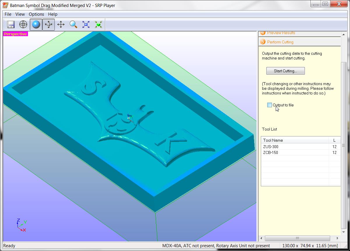
Output toolpath to file and send to machine
Toolpath is now created. Then milling started
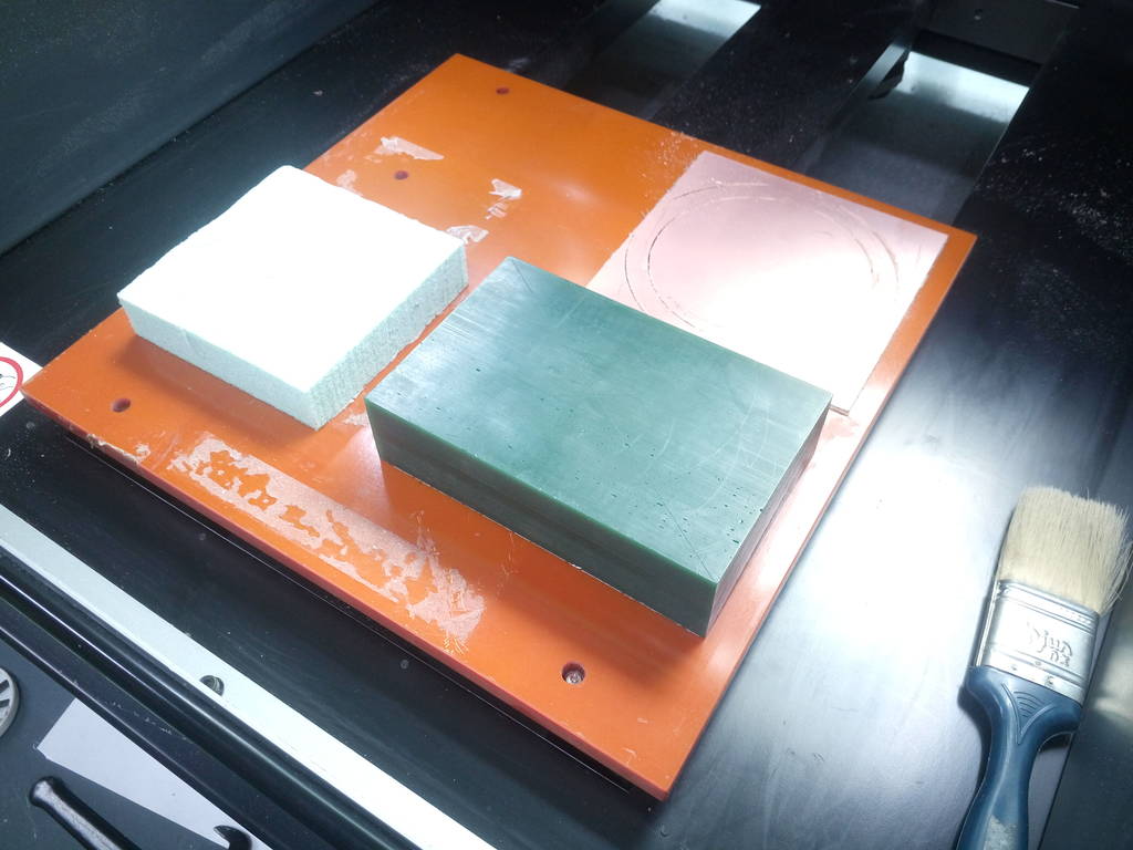
IMG_20171002_144652.jpg
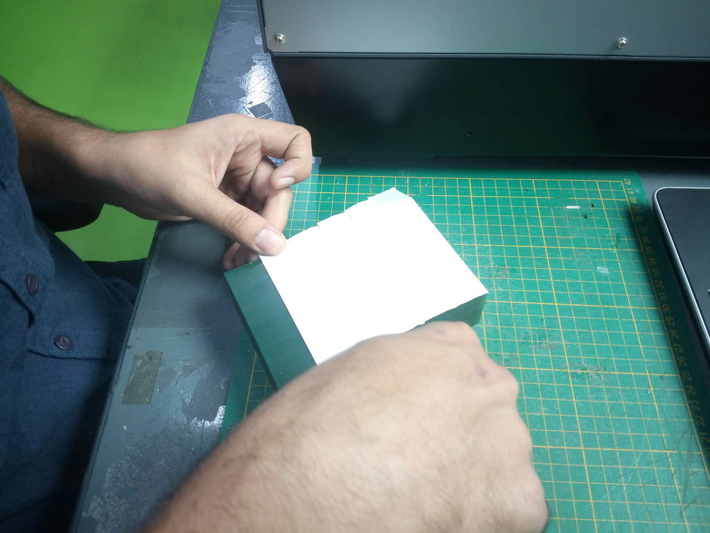
Double sided adhesive tape stick to bottom side of wax block
IMG_20171002_144655.jpg
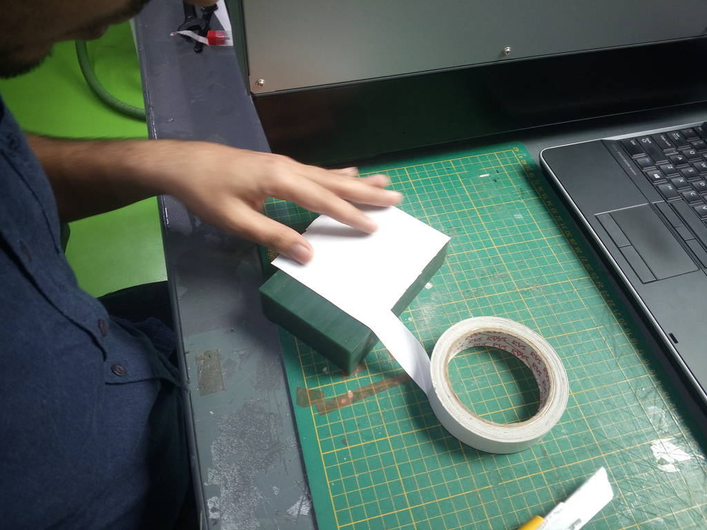
Double sided adhesive tape stick to bottom side of wax block
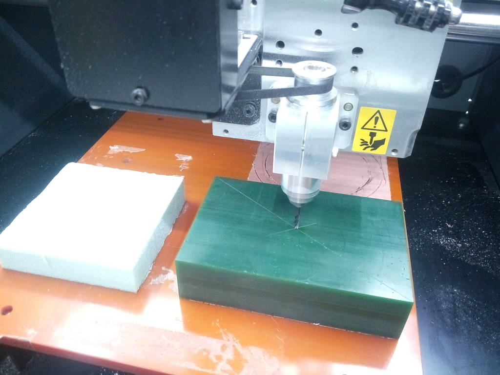
IMG_20171002_145316.jpg
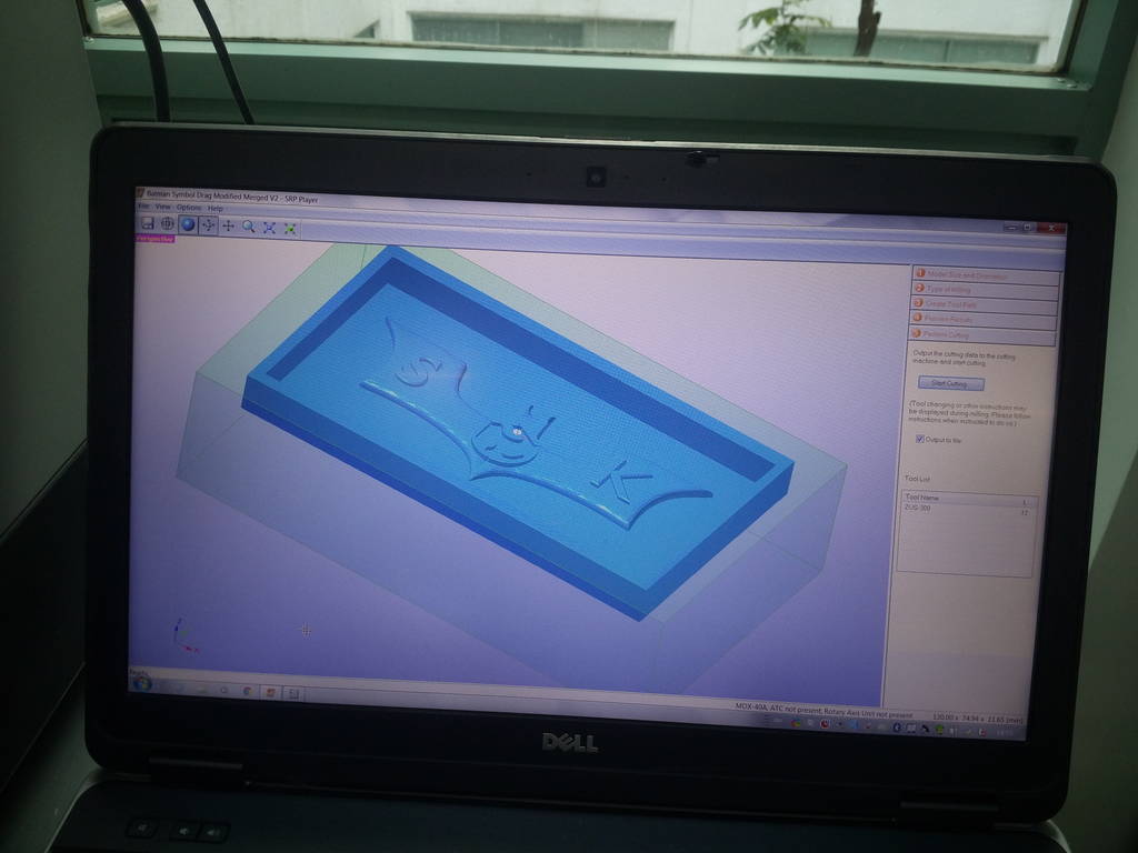
Model is loaded in SRP player and program made as shown in slidshow above
IMG_20171002_145321.jpg
Wax box is placed on machine table. Due to double sided adhesive tape wax block will stick to machine table firmly
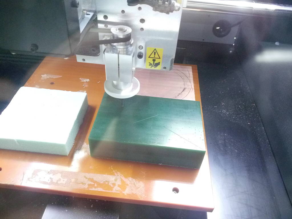
IMG_20171002_145706.jpg
Diagonally markings done to establish center of wax block. This is to take XY origin for MDX-40 milling machine
IMG_20171002_145858.jpg
Z axis origin set on top surface of wax block but slightly besides XY origin
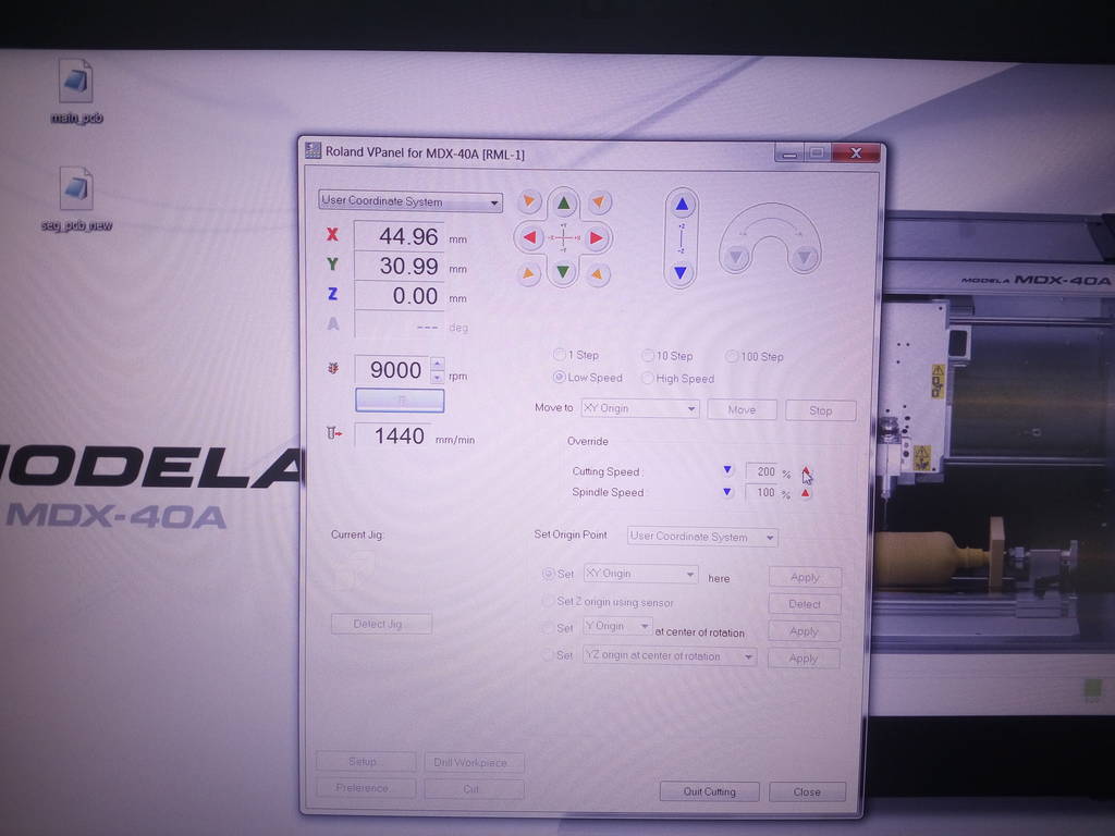
IMG_20171002_150140.jpg
Roland Vpanel is used to position machine spindle and run program generated by SRP Player
IMG_20171002_150154.jpg
Milling started with first cut as a clean cut and then first ramp to take a depth of cut on 3 mm
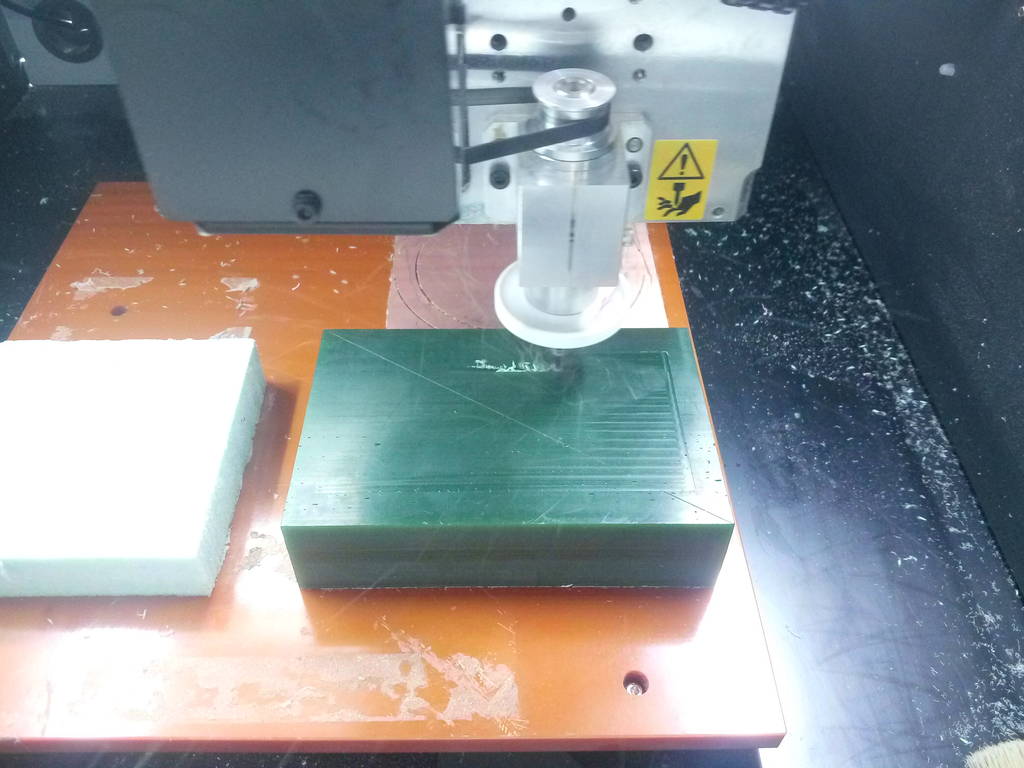
Roughing cut progresses
After few cuts of 1.8mm each its seen that material removal is normal without any issues.
At some places machine had drilled holes wherever there are cavities
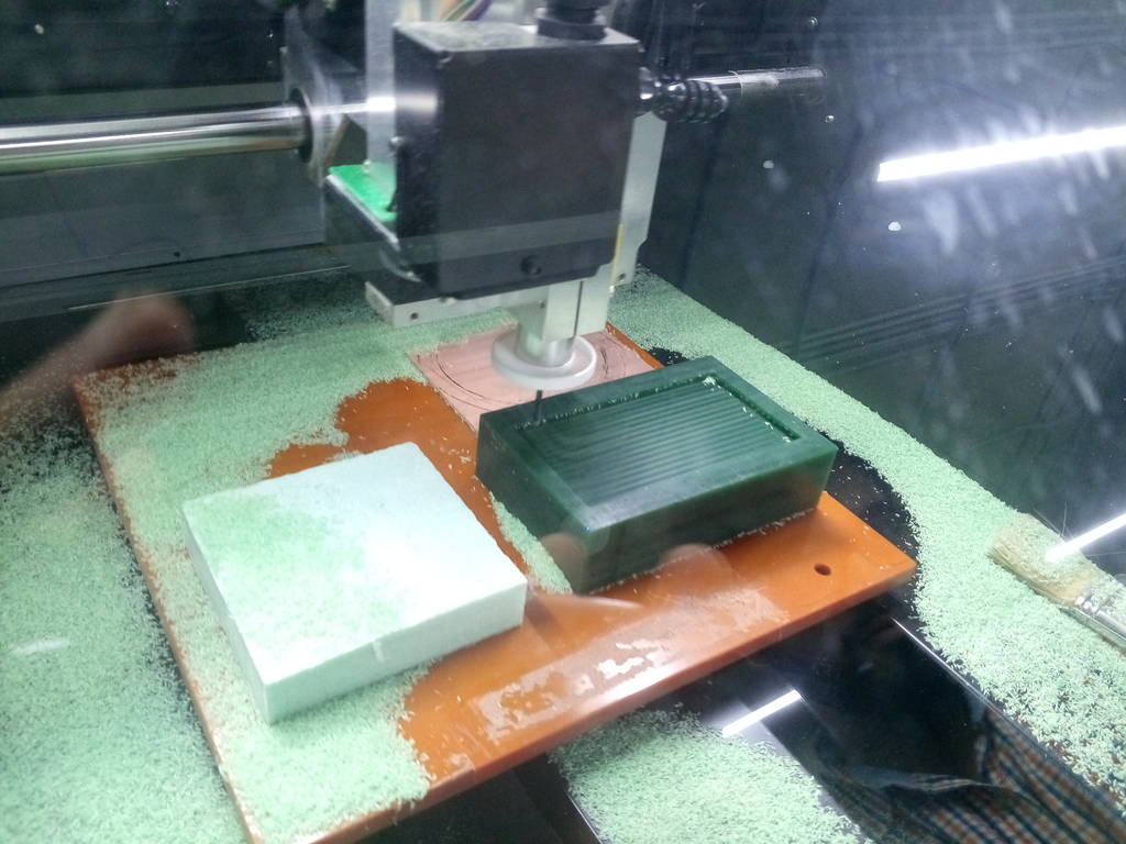
After several minutes
Top letters and central symbold started appearning
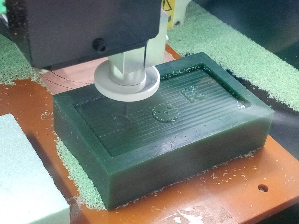
Symbol letter and shape can now beclearly visible
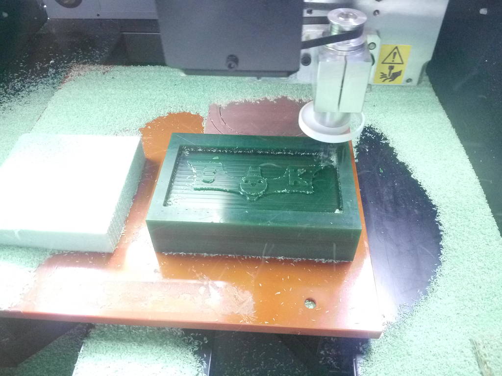
IMG_20171002_151659.jpg
Roughing final
IMG_20171002_152155.jpg
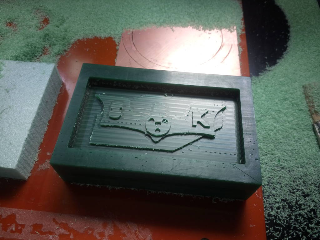
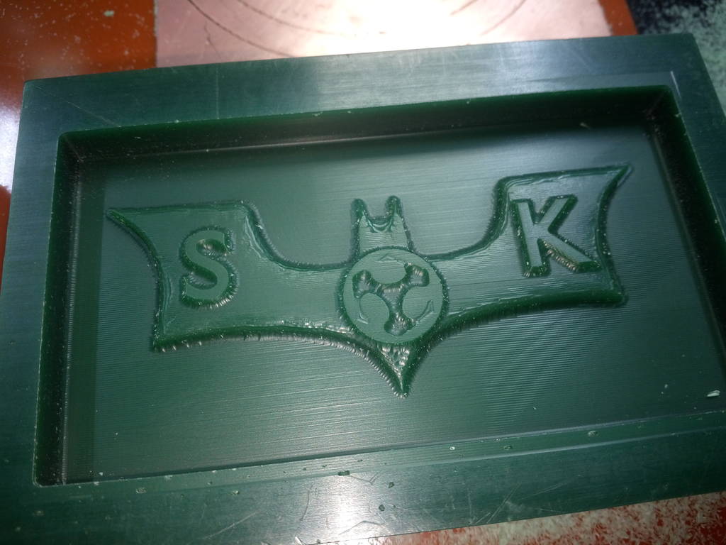
Final roughing cut is completed
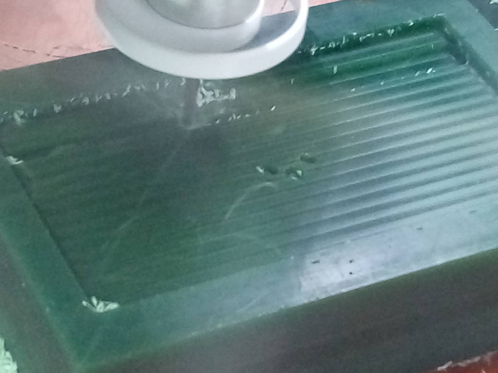
IMG_20171002_163435.jpg
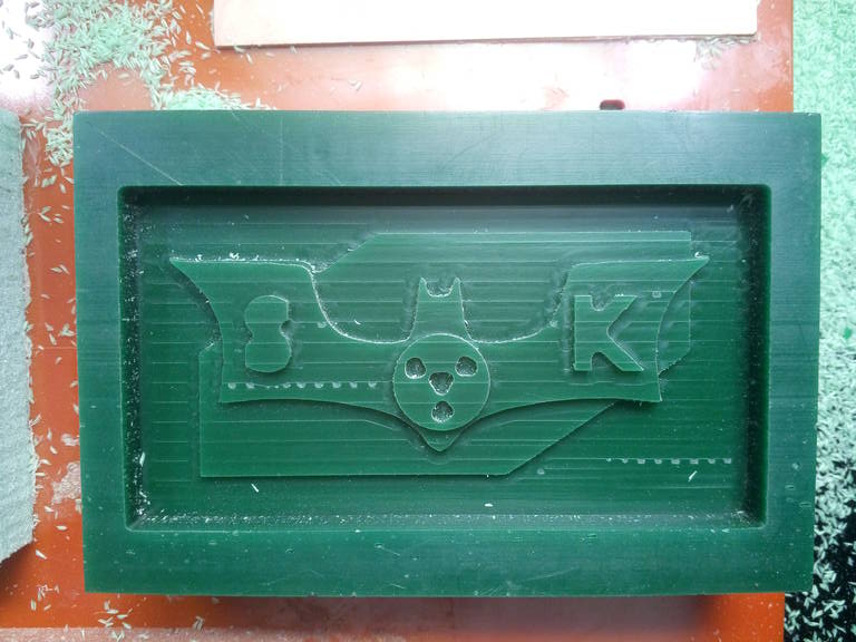
After finishing cut is completed
IMG_20171002_163605.jpg
Surface finish good enough and acceptable
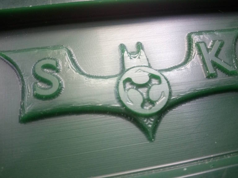
IMG_20171002_163823.jpg
IMG_20171010_182255.jpg
Using mould max 30 Silicon Rubber compound to create mould out of mould
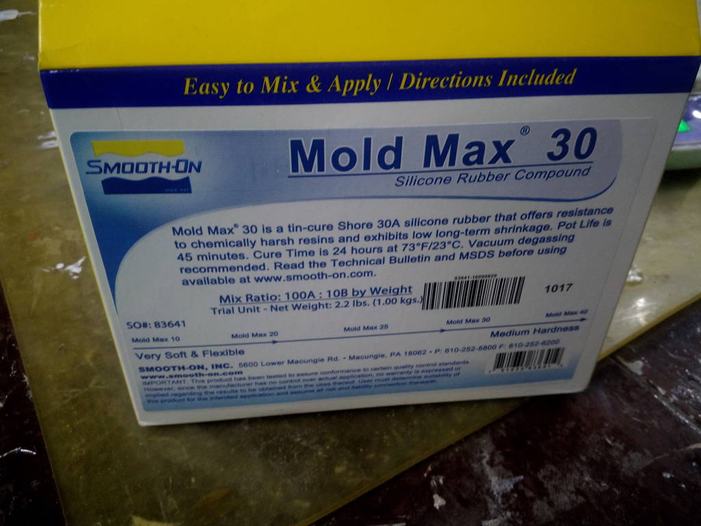
Find Material safety data sheet here Download MSDS Sheet for Mold Max
Mold max 30 is poured in mould cavity
This is kept for 24 hours. There are two such parts made. One for top and one for bottom
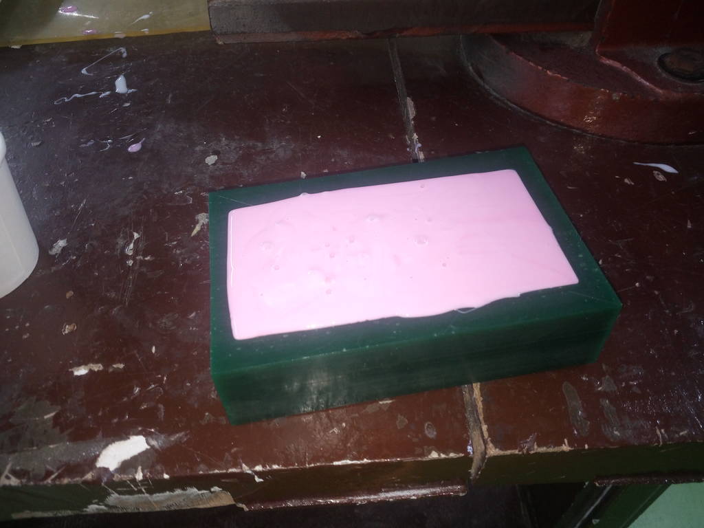
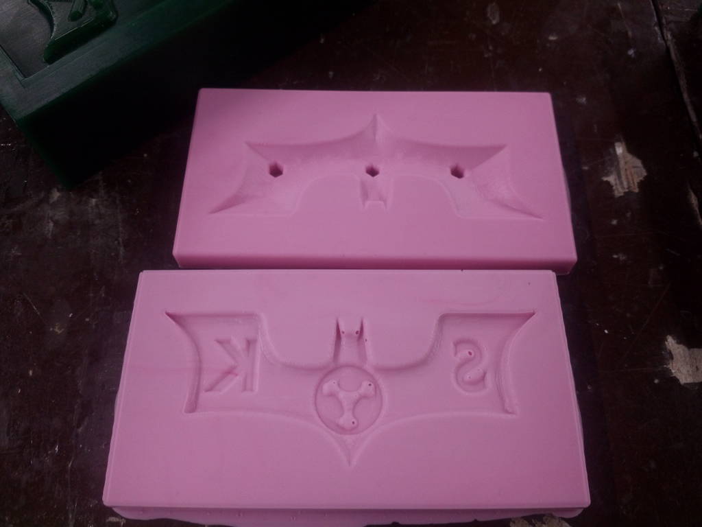
This is bottom part flexible mould is ready
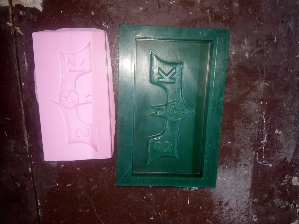
Wax mould for bottom portion look like this
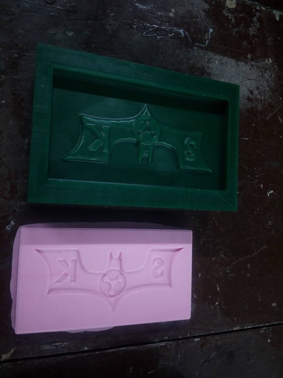
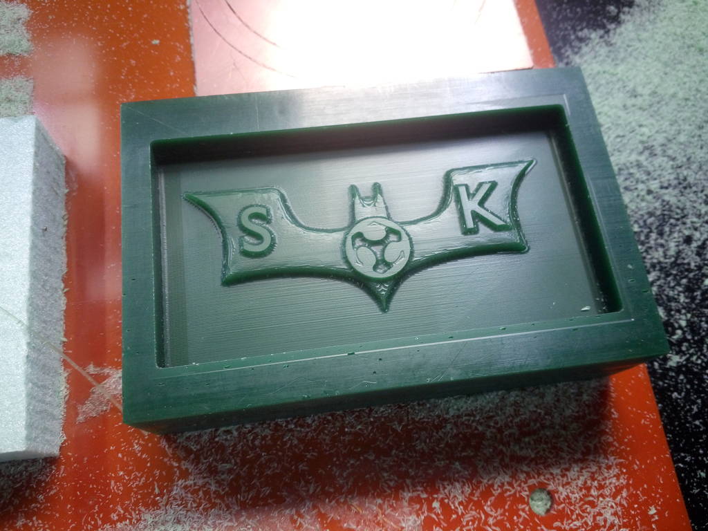
Similar procedure is followed for top part of mould
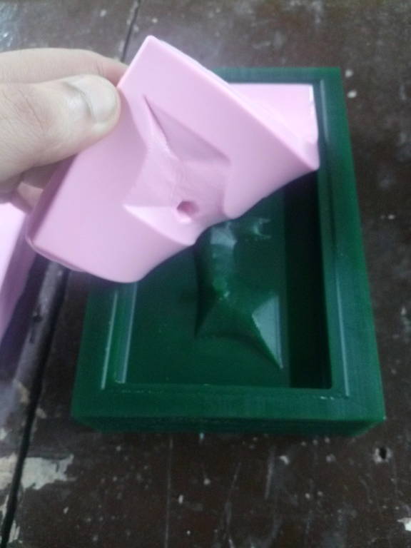
Top part of mould
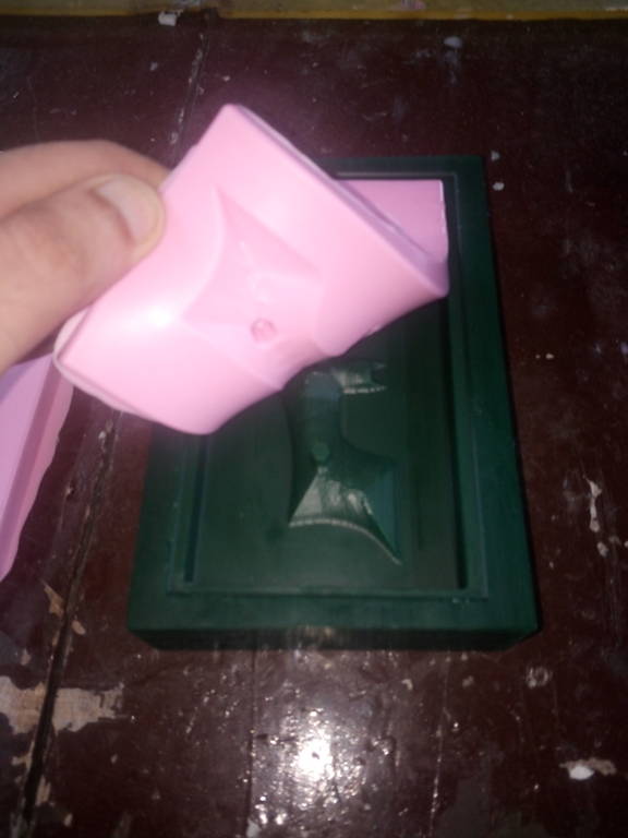
Top part of mould
IMG_20171012_183402.jpg
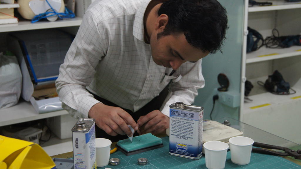
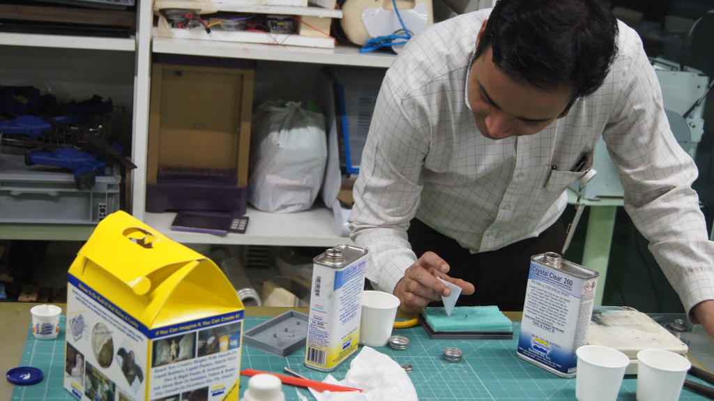
Final mould from mould is now created. I have now poured transparent resin from opening
Crystal clear transparent resin
Crystal clear transparent resin is used to create final casting of my component. Part A is mixed with part B with a ratio of 100A:90B
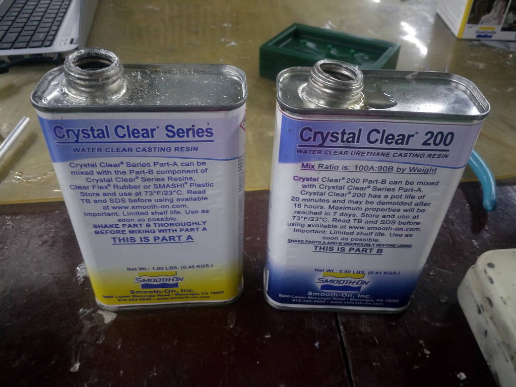
Find Material safety data sheet here Download MSDS Sheet for Crystal clear 200
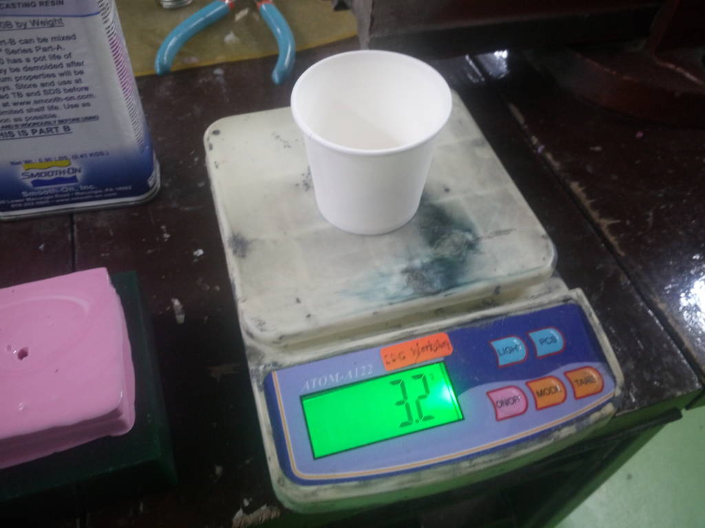
100/90 ratio is mixed in a cup
Crystal clear resin to be mixed 100/90 ratio and mixed. Weigheing scale is used for measuring exact weight. Mixture is then poured in mould.
Pour resin mixture in mould cavity
Let resin mixture fill entire cavity of mould
After 24 hours of soaking and drying
Casting is then removed after 24 hours.
Final Casting of Batman symbol