Week 4:
Electronics Design
Electronics design is a complete unknown territory for me. This is the first time I am doing something in this territory.
I knew the basics of electronics, as I learnt it during school times. I have the knowledge of relationships between Current, Resistance and Voltage, Kirchoff's law, Transducers, Boolean Logic etc. But I have zero experience in making circuits. Due to Fabacademy I came to know about various ways you can create circuits, using Printed circuit boards and Integrated Circuits. I came to know about "Microcontrollers" as well which can be used to create simple computation, and how can we use a microcontroller to program another microcontrollers.
FabISP
FabISP is a circuit designed to program other microcontrollers. It is an In System Programmer (ISP). An ISP can basically be used program a microcontroller, while it is installed in a complete system, rather than pre-programming it before installing it. The primary advantage of this feature is that it allows manufacturers of electronic devices to integrate programming and testing into a single production phase, and save money, rather than requiring a separate programming stage prior to assembling the system. This may allow manufacturers to program the chips in their own system's production line instead of buying preprogrammed chips from a manufacturer or distributor, making it feasible to apply code or design changes in the middle of a production run.
FabISP is an open-source design of an ISP, which one can make in any fablabs, as all of the components are available as a part of the Fablab Inventory. It contains ATtiny44 as the microcontroller.
To start off with, I downloaded the following images of the circuits from the Fabacademy website.
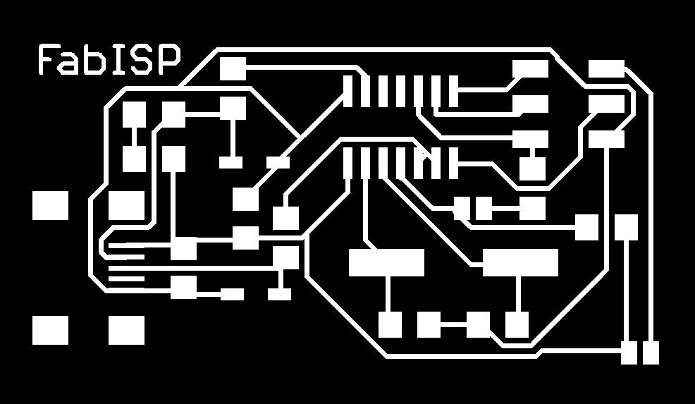

I used those images and used the fabmodules, to generate the ".rml" file and used the Roland machines, to mill the circuit traces, on a blank copper coated board.
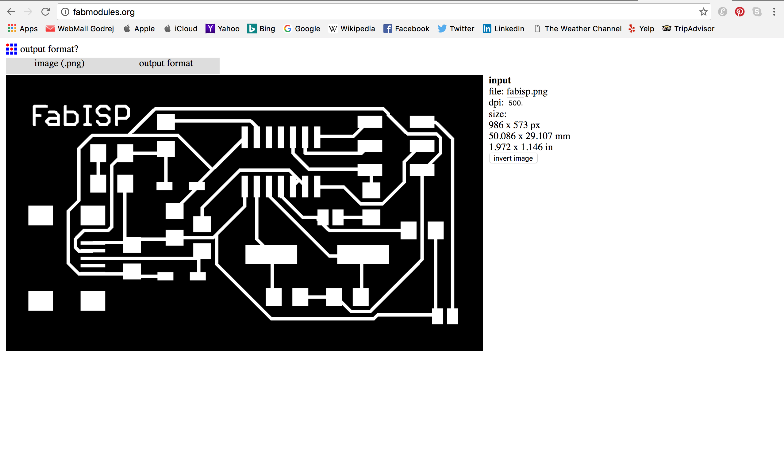
I uploaded the images on the fabmodules.org. The images were in png format.
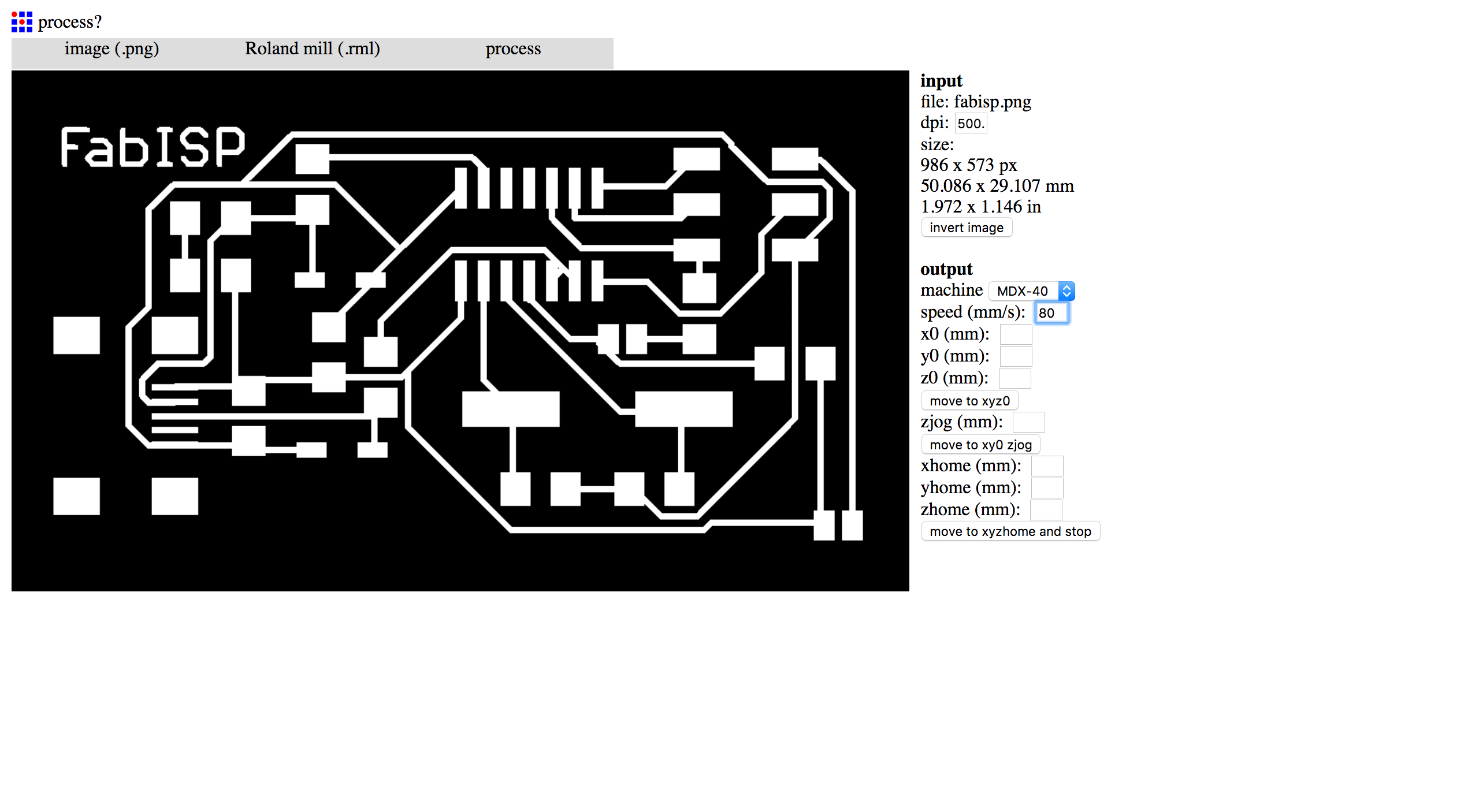
Then I selected .rml as the ouput file because the machine we are going to use, accepts that file format.
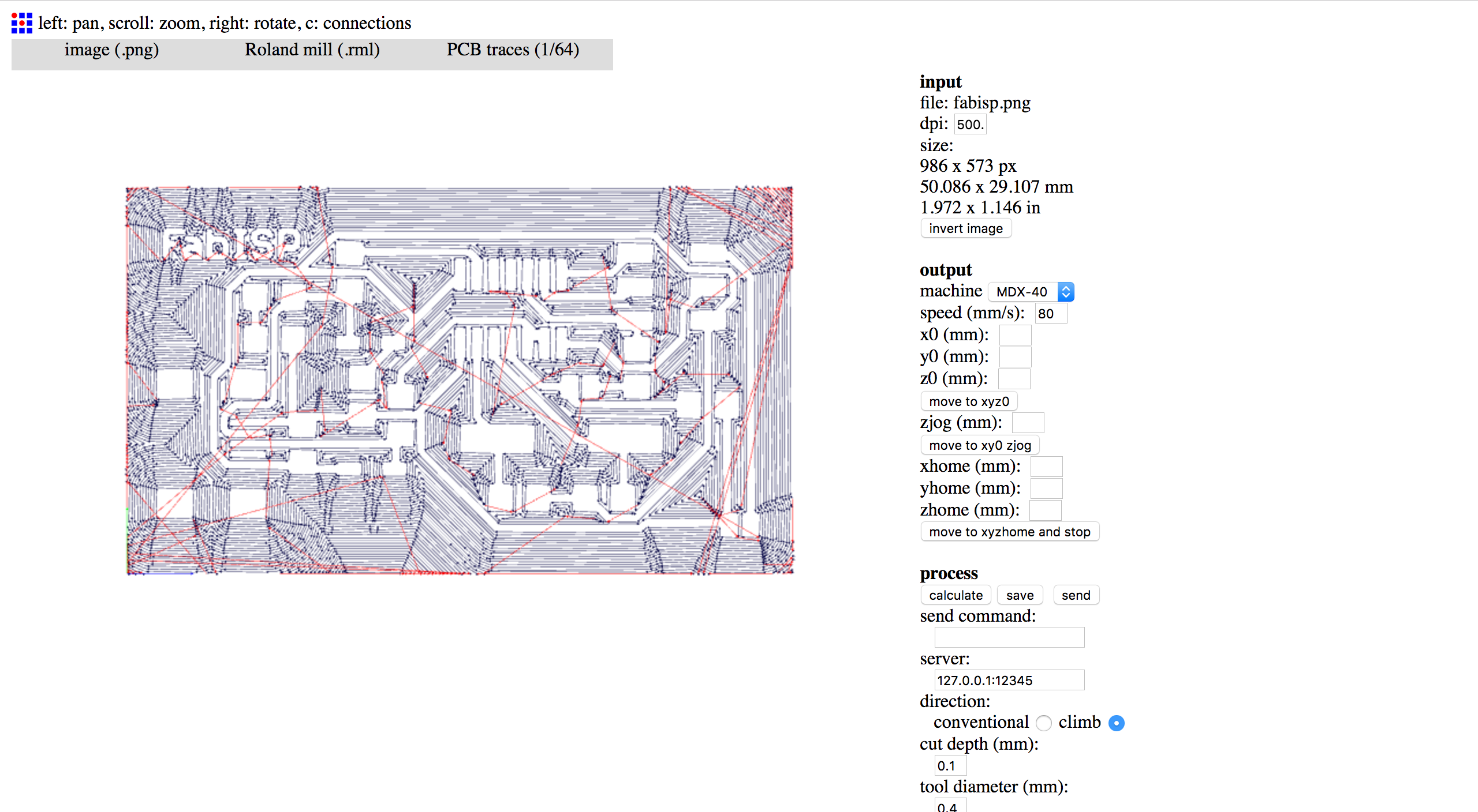
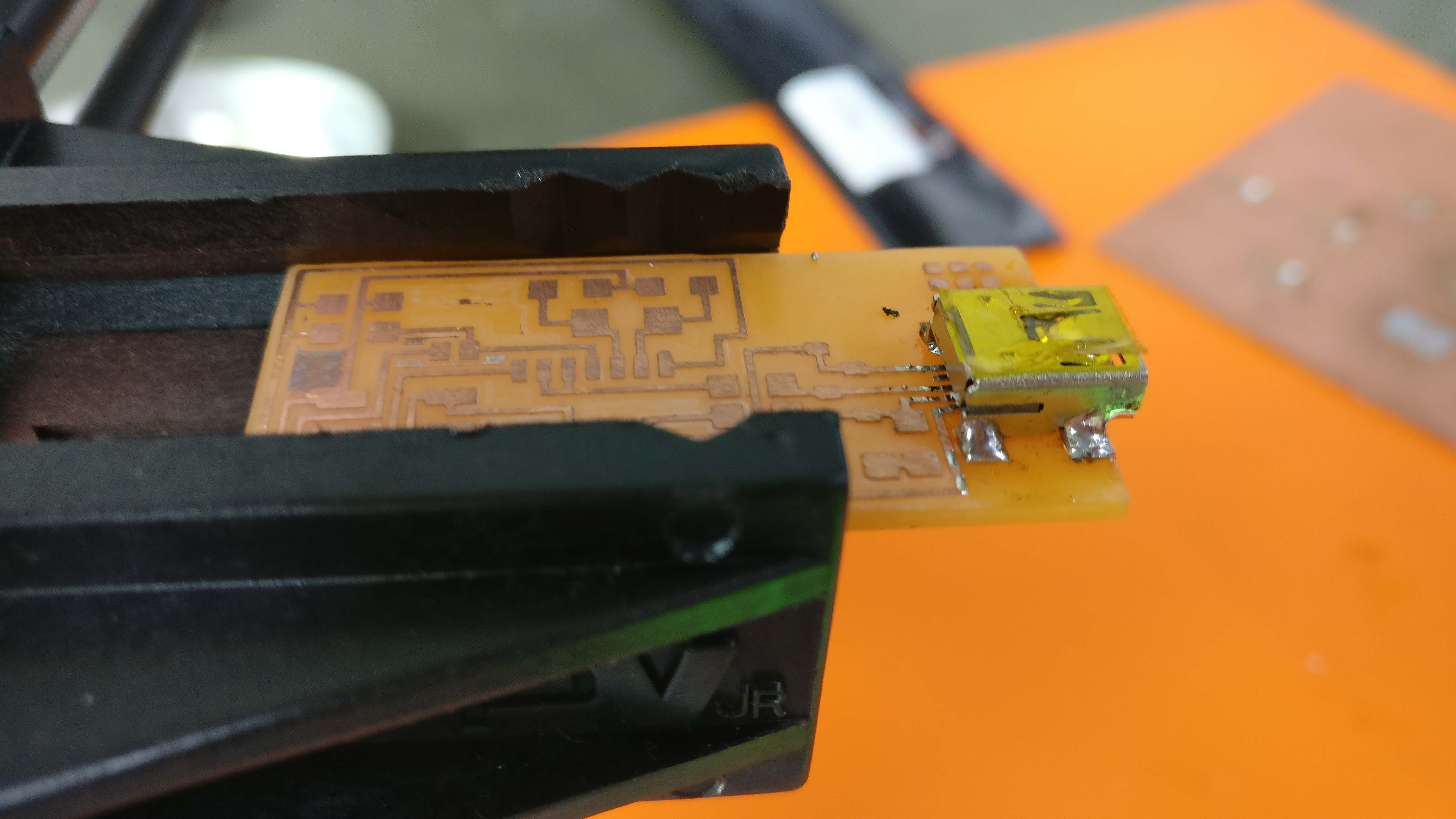
I selected the 1/64th inch as I wanted to mill the traces out first. And later carried the same process out for the outline, using 1/32th inch setting to cut it out of the main board. After doing that, I started soldeing it. I started of with the mini-USB Type B.