POLY[BOTICS]
The objective of the final project is mainly to develop an idea where you implement some fabrication skills and techniques you have learnt throughout the fab academy program. To develop a project where it becomes a potential of further development.
Requirments:
To have at least 3 different fabrication techniques including electronics and programming as one obligatory skillReleased: 07.06.2017
Week19: project development
References:
Experience
I have my interest in robotics and robotic fabrication since a year now, and i have my interest in self organizing swarms and self assembly robotics. I decided to develop the self organizing concept as my final project and push it as much as i can in two weeks.
The Intention was to let the robots communicate and talk to each other for the purpose of self organizing for a certain order, and one of these orders is following the light by having a phototransistor.
The way of communicating is using IR sensors, where one of the configurations could be by using one robot as a leader and the rest as slaves, or make them all equal in function and give them all one order, like walking in straight line with a specific distance in between, or turning clockwise or counter clockwise, or any other order that you can program and make your own library out of it.
The project has a lot of parameters and challenges considering and to understand, to test before finalizing, like the 3d printed robot: how many legs, what is weight of it, how can you achieve a balanced model. Calibrating the vibration motors was also a challenging aspect of the project, to set the needed delay between both motors, the location of the motors, how can the move evenly and so on...
Developing
I divided my project into different categories and gave each category a time frame to organize my production.
I started by understanding the concept i want to achieve and i have coded my intention using Processing which is having a swarm that is followoing a light incident.
I kicked off my research with understanding the electronics and programming part of it because it was the hardest.
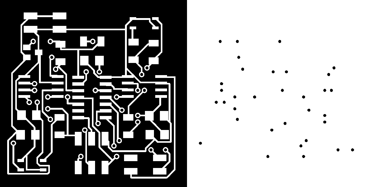
Top layer milling with holes
components:
// attiny44
// 2x pin header
// AVRISPSMD 6 pins
// voltage regulator
// 2x h-bridge
// 2x IR sensors
// 2x 10uF capacitors
// 2x .1uF capacitors
// RGB LED
// 3x 10K resistor
// 1K resistor
// 2x 100 resistors
 Bottom layer milling with holes
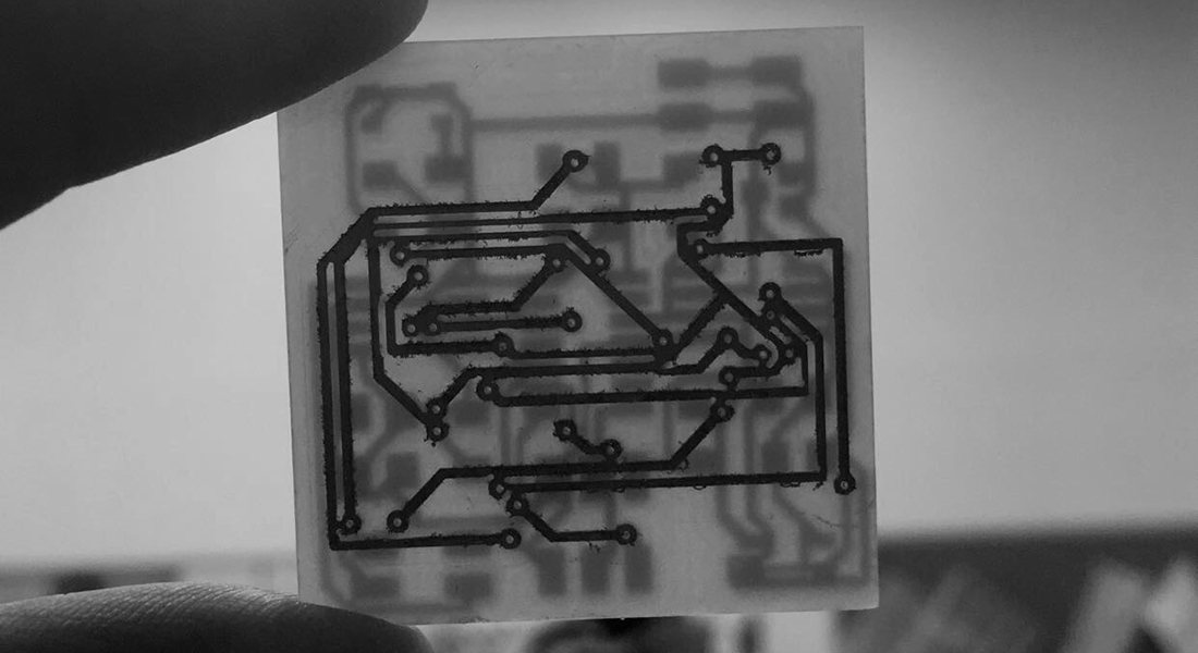
milled PCB: I have tried double sided milling because i wanted to achieve the smallest PCB possible for the robot so it the whole design would be small but i had a lot of difficulties connecting both layers together so i decided to take a .........

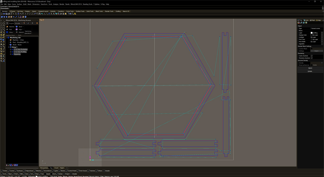 milling the robots enviroment
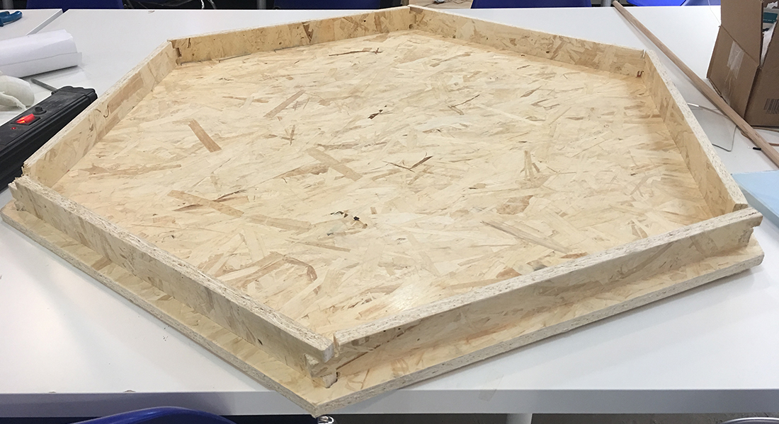
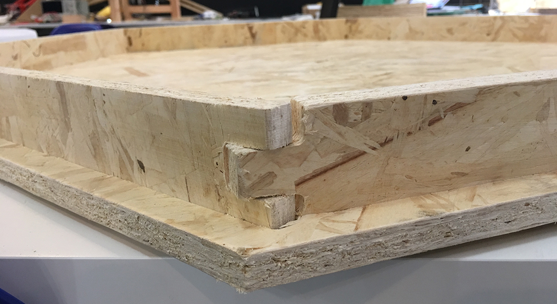
Have not thought that the robot itself has a lot of parameters that i needed to consider while modeling it:
// The weight of the print
// The design of the legs and how many of them
// The placement of the board
// The polygon design
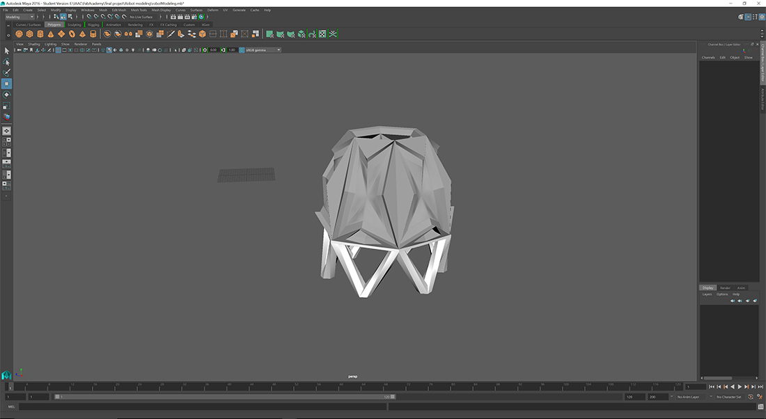 Modeling my robots using Autodesk Maya
 .jpg) preparing 3d printing files | Top part
preparing 3d printing files | Top part .jpg) preparing 3d printing files | Base
preparing 3d printing files | Base 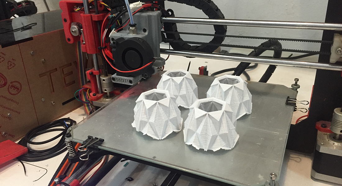
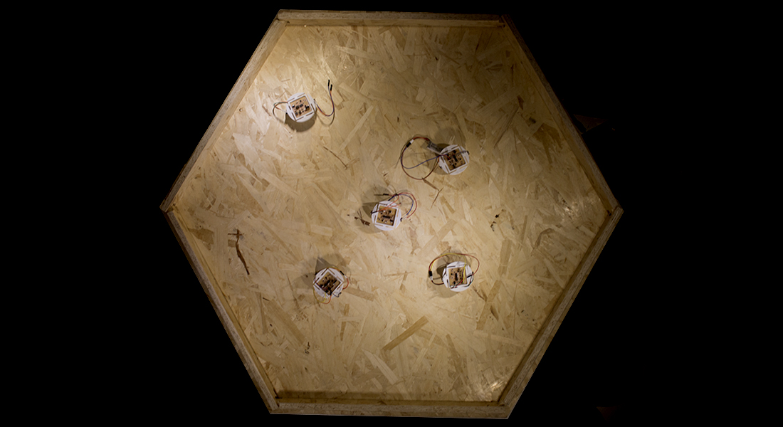
 Robots are ready to attack!
 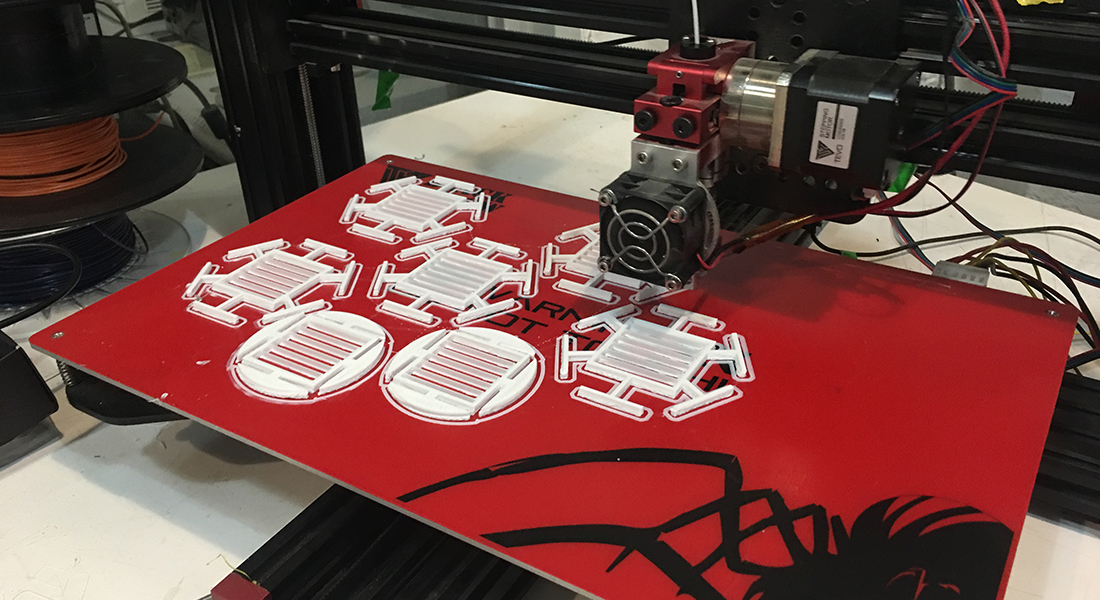 Printing the modified version of the robot
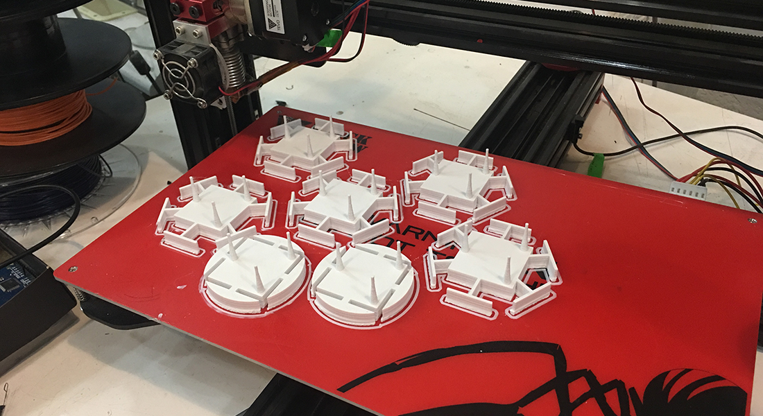
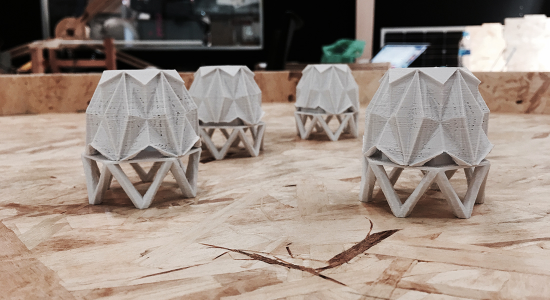
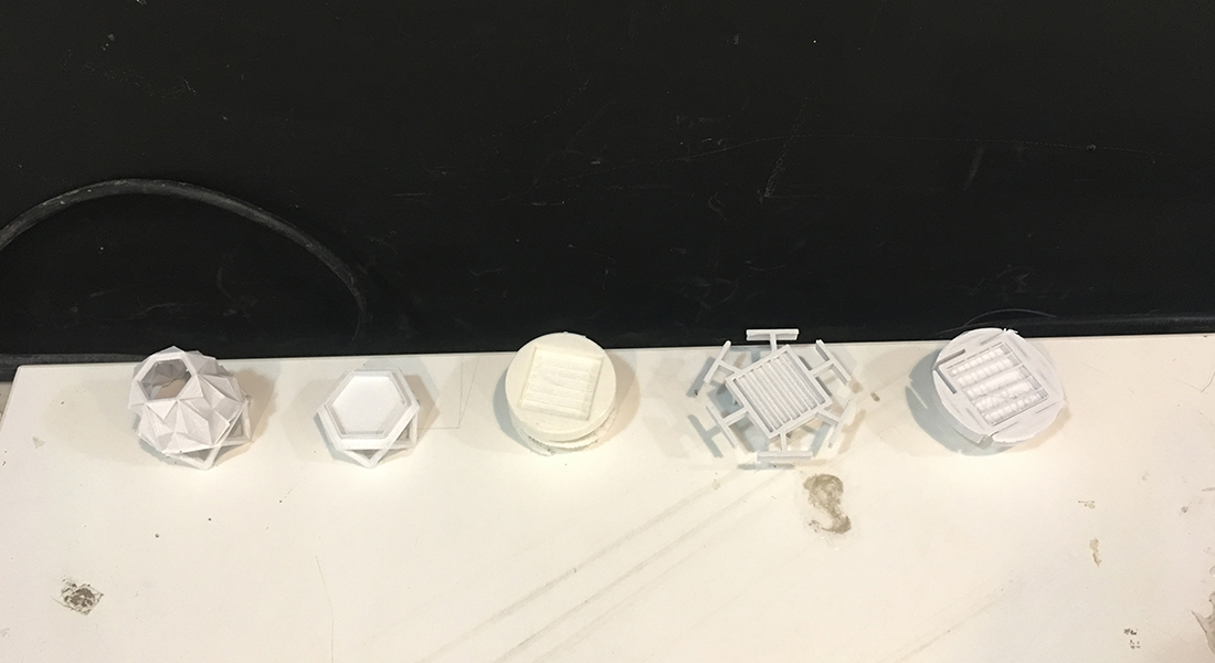 different iterations and polygons of mini robots
 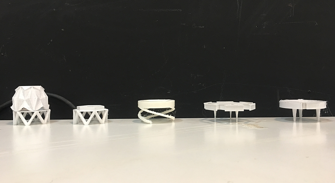 different iterations and polygons of mini robots
 After sorting out Milling and 3D printing, i had some time to revisit the electronics and programming part of the project and fix it for the final production.
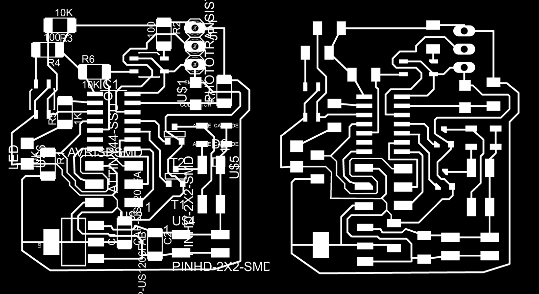
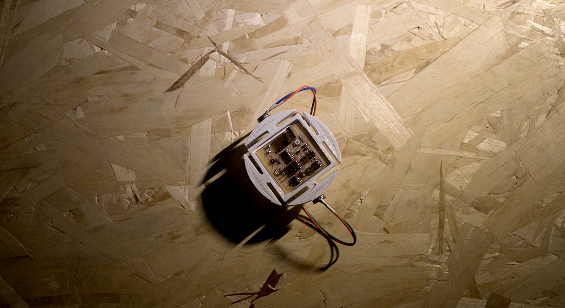
I Modified the circuit design by removing the unneeded components like the h-bridges and adding the needed ones like n channel mosfet and diods for the vibration motors. I also tried to place all the components on one layer and i achieved that with 35mm x 35mm squared PCB
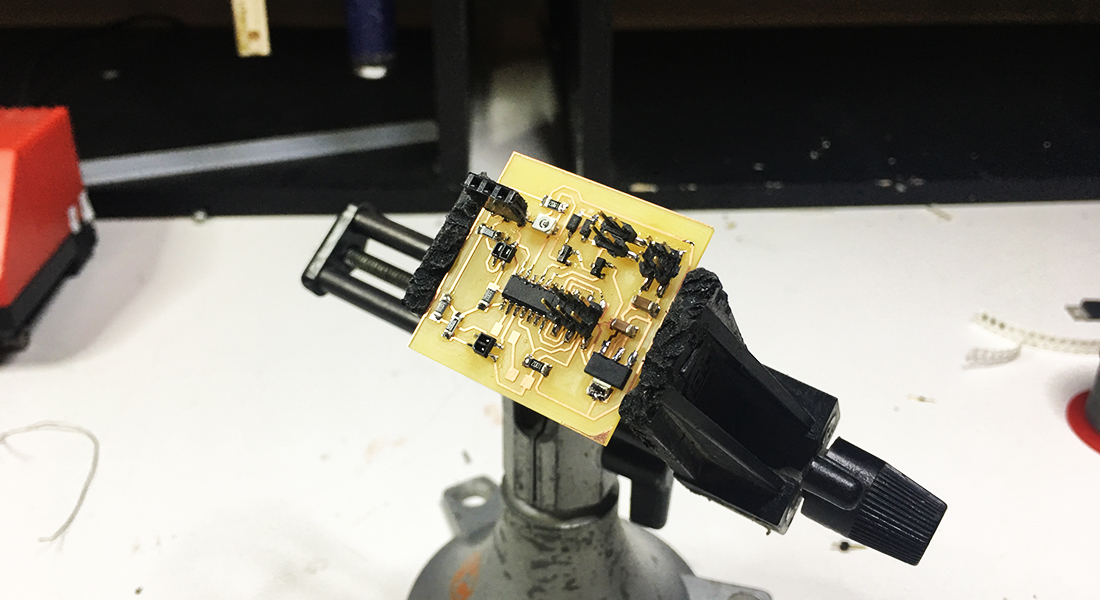 milled and soldered PCB
Assembly variant:
C1 CAP-US1206FAB C1206FAB fab (30.67 57.42) R90
C2 CAP-US1206FAB C1206FAB fab (34.88 55.8) R270
D1 ZENER DIODE 3.3V SOD123 fab (43.11 69.76) R180
D2 ZENER DIODE 3.3V SOD123 fab (43.11 69.76) R180
IC1 ATTINY44-SSU SOIC14 fab (29.16 72.9) R270
JP1 1X03 pinhead (40.45 83.31) R270
R1 10K R1206FAB fab (20.04 66.96) R270
R2 100 R1206FAB fab (36.12 85.01) R270
R3 10K R1206FAB fab (21.71 86.23) R180
R4 100 R1206FAB fab (20.01 82.82) R180
R5 1K R1206FAB fab (22.4 74.12) R90
R6 10K R1206FAB fab (26.49 79.77) R0
R7 10K R1206FAB fab (44.5 77.07) R90
T1 N-CHANNEL MOSFET SOT-23 fab (37.79 65.26) R180
T2 N-CHANNEL MOSFET SOT-23 fab (37.64 71.12) R180
U$1 PHOTOTRANSISTOR-NPN1206 OP1206 fab (40.55 76.74) R90
U$2 AVRISPSMD 2X03SMD fab (29.4 64.16) R180
U$4 PINHD-2X2-SMD 2X02SMD fab (41.05 55.9) R0
U$5 PINHD-2X2-SMD 2X02SMD fab (42.72 64.31) R270
U$6 LED LED1206 fab (17.15 68.41) R270
U1 IR SENSOR QRE1113-1:1 Testing (34.09 80.74) R180
U2 IR SENSOR QRE1113-1:1 Testing (19.24 75.97) R270
U3 VOLTAGE REGULATOR 3.3V 1A SOT223 fab (23.6 56.13) R90
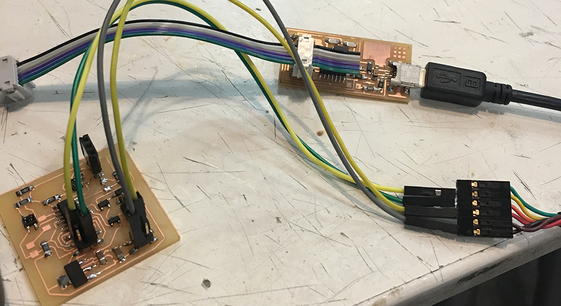 progrramming the board
 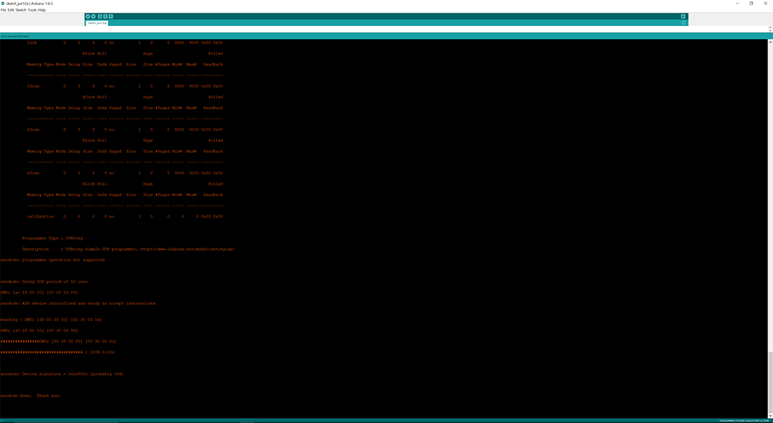 progrramming the board
 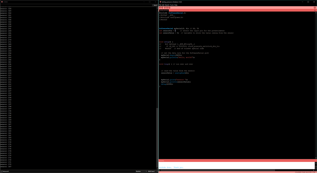 testing the sensors by serial communication
 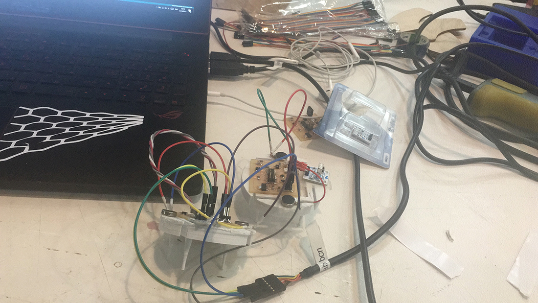 programing the robot
 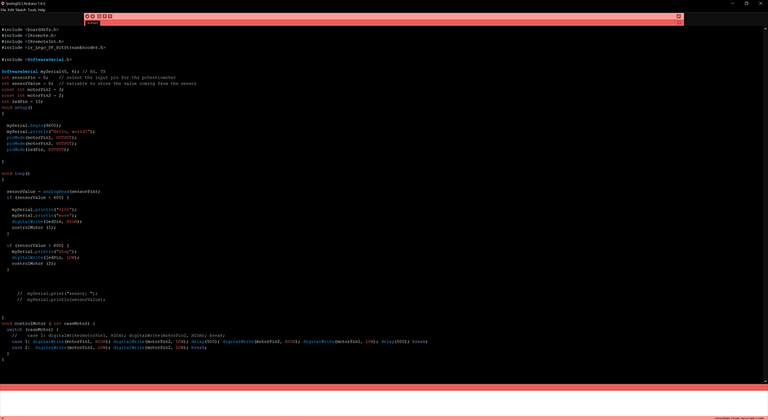 calibrating the vibration motors with the phototransistors
 After this point i have around 4 days left for the final preentation, because i am presenting the second day which is the 16th of June. I have completed the 3D printing part and the CNC milling part successfully, and i have to set up the code for the robot to define the running and delays of the motors and define the values of the phototransistors. I am almost there to sort them out because i was doing some tests initially calibrating the motors. The thing that i knd of removed from the scope is installing and debugging the IR sensors where i let it go because of the time limitation but it is a big step to add probably later when i get the time.
It has been a great intense experience, i would have loved it more if we had the time to explore and investigate more in the field. I personally had zero knowledge in electronics and its programming, but now i can deal with whatever problem and at least i can search the problem and manage to get something out of it.


This work is licensed under a Creative Commons Attribution-NonCommercial-ShareAlike 4.0 International License.