COMMUNICAT-ING
Design and build a wired &/or wireless network connecting at least two processors, and read about Serial communication, Bluetooth Basics and RF24L01 2.4GHz Radio/Wireless
Requirments:
// Described your design and fabrication process using words/images/screenshots.// Outlined problems and how you fixed them
Experience
Parallel vs. Serial:
Parallel interfaces transfer multiple bits at the same time. They usually require buses of data - transmitting across eight, sixteen, or more wires. Data is transferred in huge, crashing waves of 1’s and 0’s.
Serial interfaces stream their data, one single bit at a time. These interfaces can operate on as little as one wire, usually never more than four.
Asynchronous Serial:
Over the years, dozens of serial protocols have been crafted to meet particular needs of embedded systems. USB (universal serial bus), and Ethernet, are a couple of the more well-known computing serial interfaces. Other very common serial interfaces include SPI, I2C, and the serial standard we’re here to talk about today. Each of these serial interfaces can be sorted into one of two groups: synchronous or asynchronous.
A synchronous serial interface always pairs its data line(s) with a clock signal, so all devices on a synchronous serial bus share a common clock. This makes for a more straightforward, often faster serial transfer, but it also requires at least one extra wire between communicating devices. Examples of synchronous interfaces include SPI, and I2C.
Asynchronous means that data is transferred without support from an external clock signal. This transmission method is perfect for minimizing the required wires and I/O pins, but it does mean we need to put some extra effort into reliably transferring and receiving data. The serial protocol we’ll be discussing in this tutorial is the most common form of asynchronous transfers. It is so common, in fact, that when most folks say “serial” they’re talking about this protocol (something you’ll probably notice throughout this tutorial).
The clock-less serial protocol we’ll be discussing in this tutorial is widely used in embedded electronics. If you’re looking to add a GPS module, Bluetooth, XBee’s, serial LCDs, or many other external devices to your project, you’ll probably need to whip out some serial-fu.
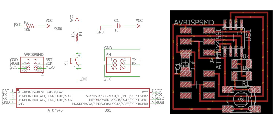 button board
 AVRISPSMD / 2X03SMD / x 2
CAP-US1206FAB / 1uf / x 1
BUTTONSMD / x 1
RES-US1206FAB / 10K / x 1
RES-US1206FAB / 1K / x 1
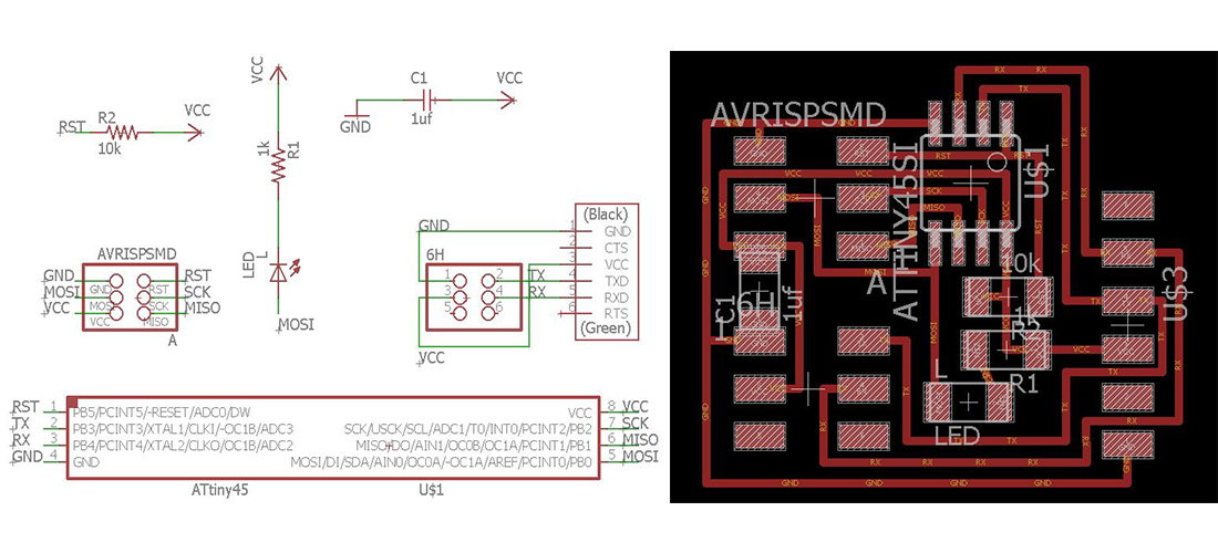 bridge board
 AVRISPSMD / 2X03SMD / x 2
CAP-US1206FAB / 1uf / x 1
LEDFAB1206 / x 1
RES-US1206FAB / 10K / x 1
RES-US1206FAB / 1K / x 1
FTDI-SMD-HEADER / 1x06SMD / x 1
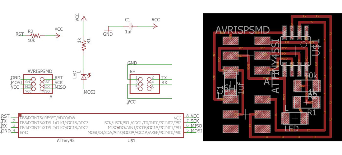 LED board
 ATTINY45SI / x 1
AVRISPSMD / 2X03SMD / x 2
CAP-US1206FAB / 1uf / x 1
LEDFAB1206 / x 1
RES-US1206FAB / 10K / x 1
RES-US1206FAB / 1K / x 1
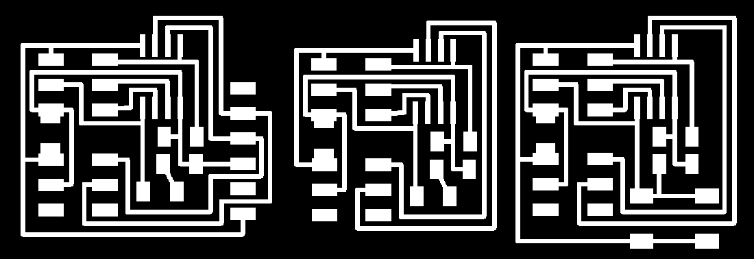 PCB traces, I have put them in one board for material efficiency
  PCB borders
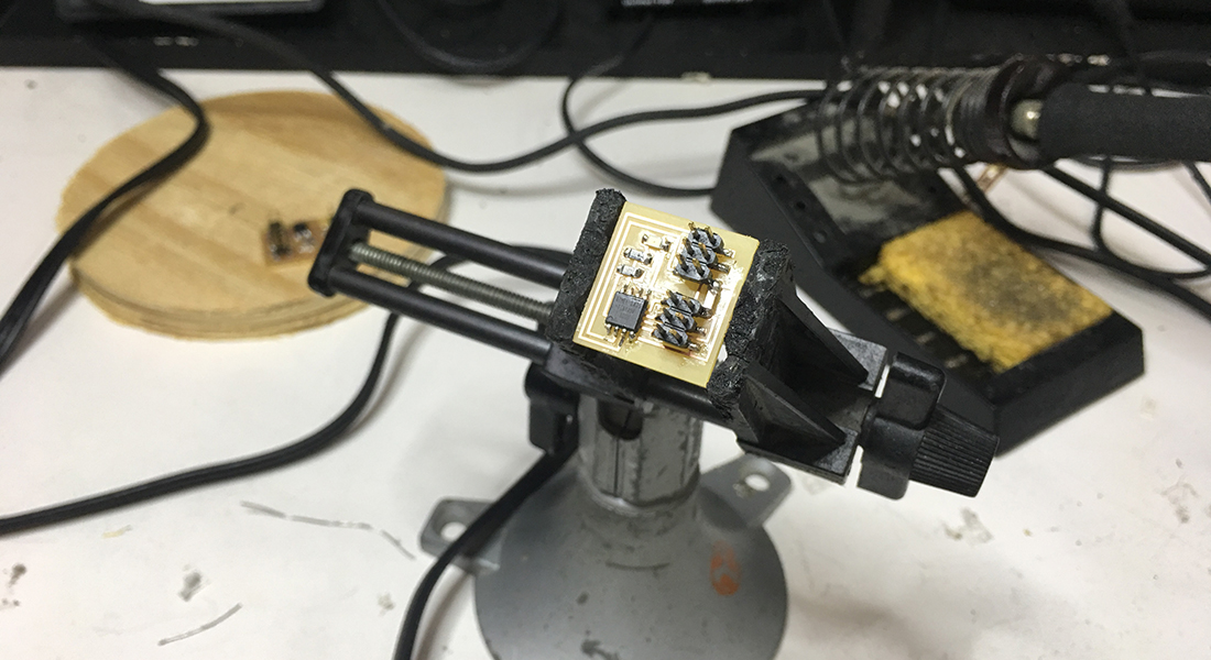
 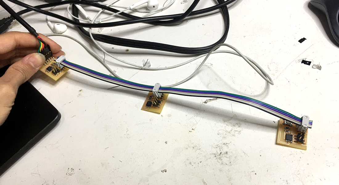 Programming...
 First I started with the bridge board then the nodes. In this case i assigned each board an ID so we can send instructions to each one. You have to find this line in the .c file: #define node_id '0'. Here you change the "0" to any ID you want to assign, I used numbers.
After changing you have to connect your FABISP to the bridge board. Next you have to go to Terminal, then the folder where your .c and .make files are and execute this: make -f hello.bus.45.make program-usbtiny. You will see that the led in your board blinks, this is because it is being programed.
Debugging
The board with the push button also had an LED. So changed the code to make that also blink when the button is engaged. This way I can make sure the board is working.
Next i took the LED board and connected the Rx pin to an FTDI cable and manually send the keyword for turning on the LED, which worked fine.
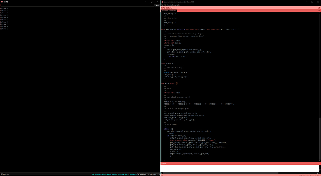
So went back to the first board and checked what it is transmitting using the FTDI cable and a PC to collect the serial data. When the button is pushed instead of the keyword something weird was sent. I tried varying the baudrate, double checking the code.
LED Serial Bus
Check the code hello.bus.45.c in the downloading files
What we did is a simple serial communication with the help of softwareSerial library. This library essentially handles all the challenges of serial communication like having the clock, interrupts and protocol for sending and receiving data.
I named the same nodes with node names 1, 2 and 3. All of them will blink only when it is addressed. By default for node 1 and node 2 the LED will be ON but it will be OFF for node 3.
1 | /* |
Programming Led and button
As i mentioned earlier that I had some problems figuring out the code for the button, i had to try it on one of my firends laptop Thomas. Finally we thought that it might be because of wrong timing as I was using the internal clock, which is not reliable. I switched to the external 20 MHz and reprogrammed the board, which actually solved the issue.Check the code hello.bus.bottom.45.c in the downloading files