OUTPUT-ING
The objective of this assignment is to Add an output device to a microcontroller board you’ve designed and program it to do something. And to demonstrate workflows used in circuit board design and fabrication to implement and interpret programming protocols.
Requirments:
// Described your design and fabrication process using words/images/screenshots.// Explained the programming process/es you used and how the microcontroller datasheet helped you.
// Outlined problems and how you fixed them
// Included original design files and code
Released: 29.03.2017
Week10: output device
References:
Experience
I Have decided to go for the stepper motor because we needed it for the machine design assignment so I followed Niel's board Niel's board for programming a stepper motor. I followed the same process for designing my microcontroller, I made a schematic and then the board, exported the .eps file to made the traces and outlines .png, respecting the scale in order to process the files in the fab modules.
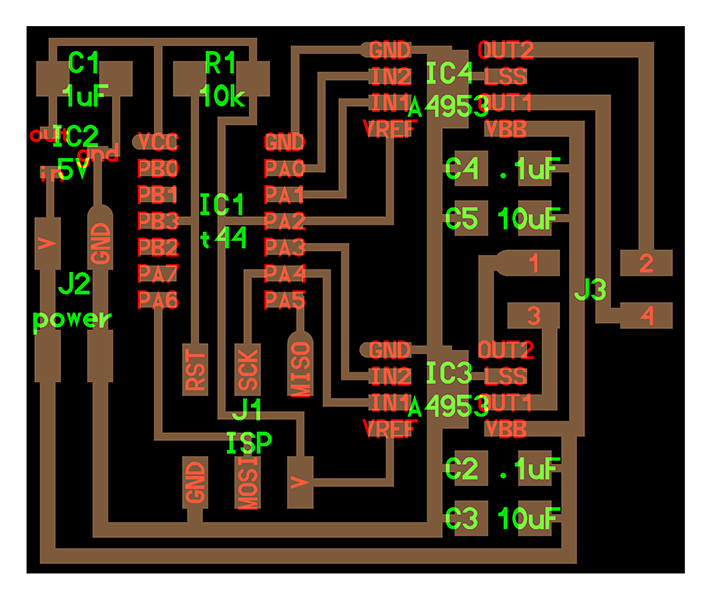
Soldering components:
A 4953
3 Capacitors 1uf
2 Capacitors 10uf
Resistor 10 k
2 Four Pin Header
1 Six Pin Header
Bridge 5V
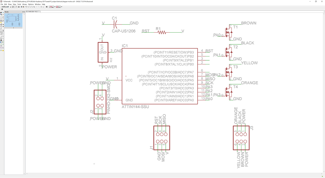 Schematic Eagle
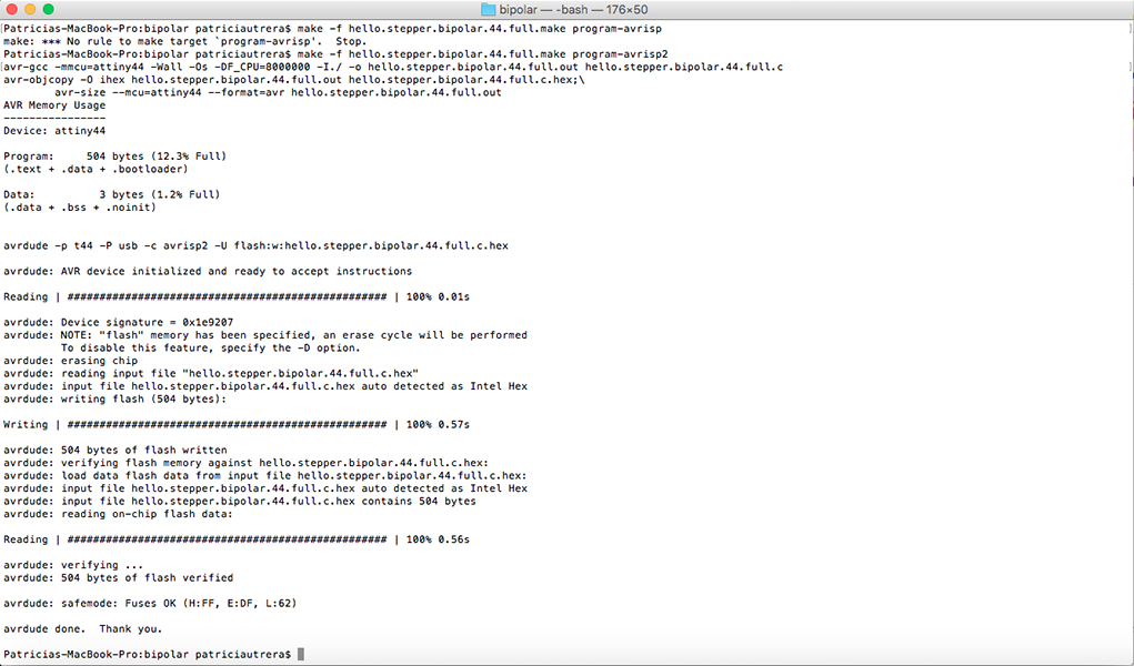
Download the make file and make sure the file is set for the atTiny44. I have used the AVRISP2 to program my board and once you get something like the image above it means your board has been programmed successfully.
In Neil's script you have to define few parameters in order to make the motor understand the C code.
most importantly:
#define the output
#define the pin
#define the port
#define the Pulse-width modulation (PWM)
#define the step counts
What is PWM duty cycle?
Electrical motors typically use less than a 100% duty cycle. For example, if a motor runs for one out of 100 seconds, or 1/100 of the time, then, its duty cycle is 1/100, or 1 percent. Pulse-width modulation (PWM) is used in a variety of electronic situations, such as power delivery and voltage regulation.
And Neil's code is defined by 100 PWM cycles and 20 steps
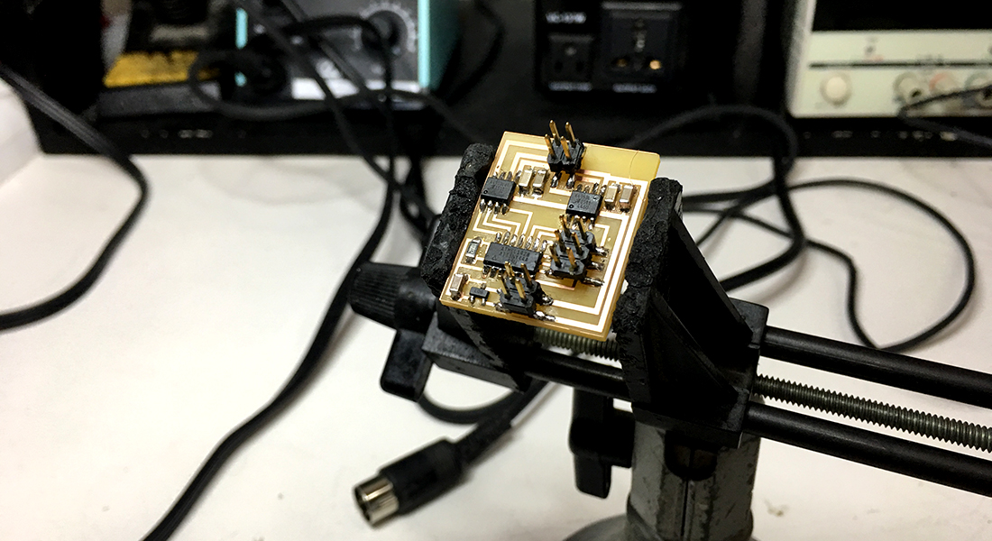
I had a problem when i was turning on the powersupply, setting the current at 1A and the voltage at 9V or 12V but never had it running for some reason, we have tried cleaning, reconnecting, resoldering, reeverthing but still didnt work until we started increasing the current.