solar3 from jc thuan on Vimeo.
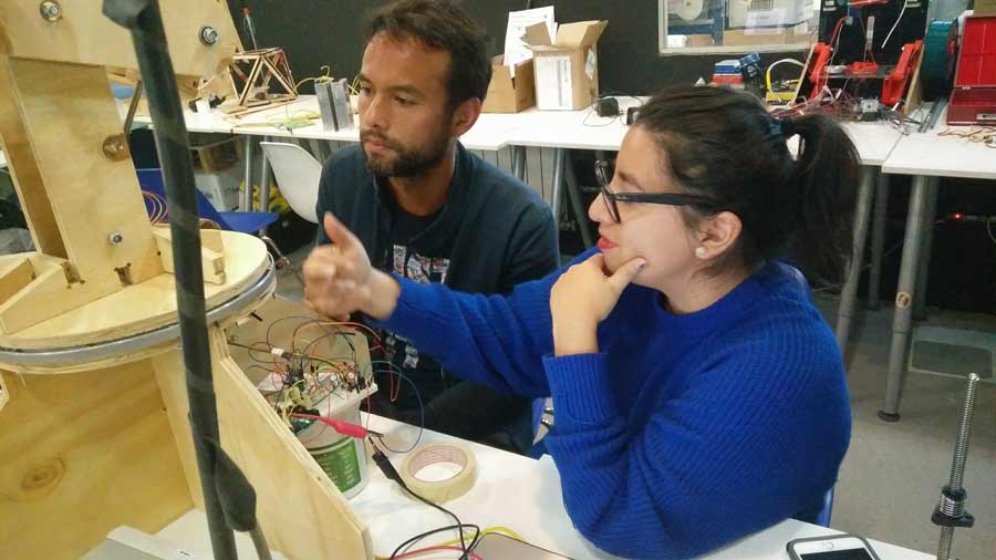
Dominic Moore (Machine Design)
trinidad Gómez Machuca (Programming)
links (Triny please modify)
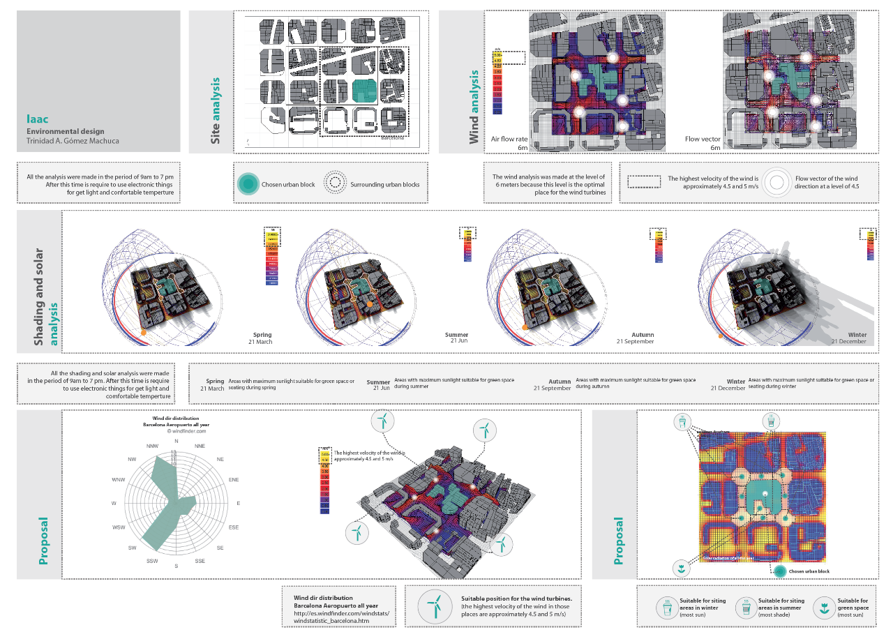
Sun movements in Barcelona
Here you can see a diagram that explains the sun’s behaviur in a specific block in Barcelona...
SUNS MOVEMENT AND CYCLE STAGES
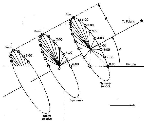
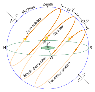
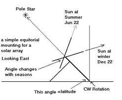

Sun And the Seasons:
http://physics.weber.edu/schroeder/ua/sunandseasons.html
References
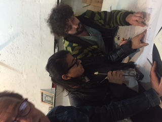
First we decided to make some research in order to better understand how a Solar tracker works... The mechanism and overall design features of such a system; including motors gears, coding, materials, environmental factors, etc.
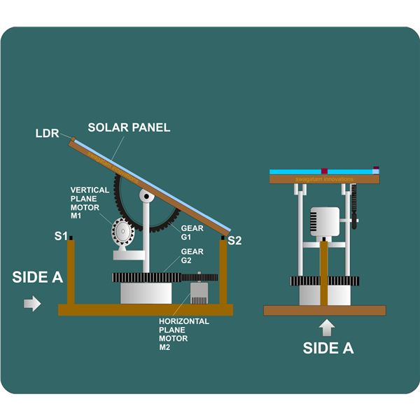
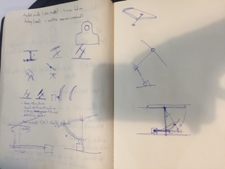
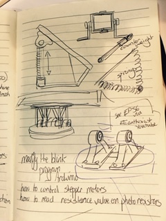
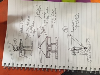
Our prototype needs to act in two axis - ’x’ and ’y’. Conclusions we made were that there are three main conventional ways to make this system function mechanically. Either a linear actuated system, a geared or pulley driven system or by combining both these types. See below...
*
*
*
![]()
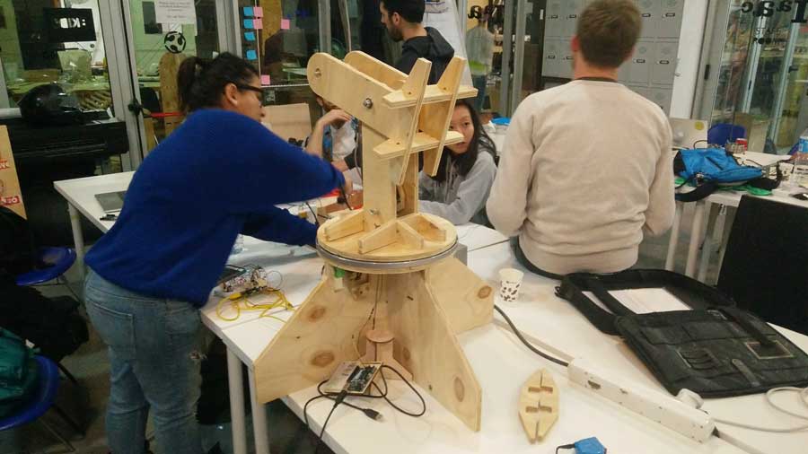
Solar Tracker
Solar tracking device used to optimise solar cells charging (22nd march)
![]()
LED photo-resistor values related to light intensity in Lux:

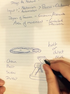
PROCESS
Brain-Storming potential solutions: - 22nd March
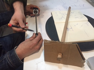
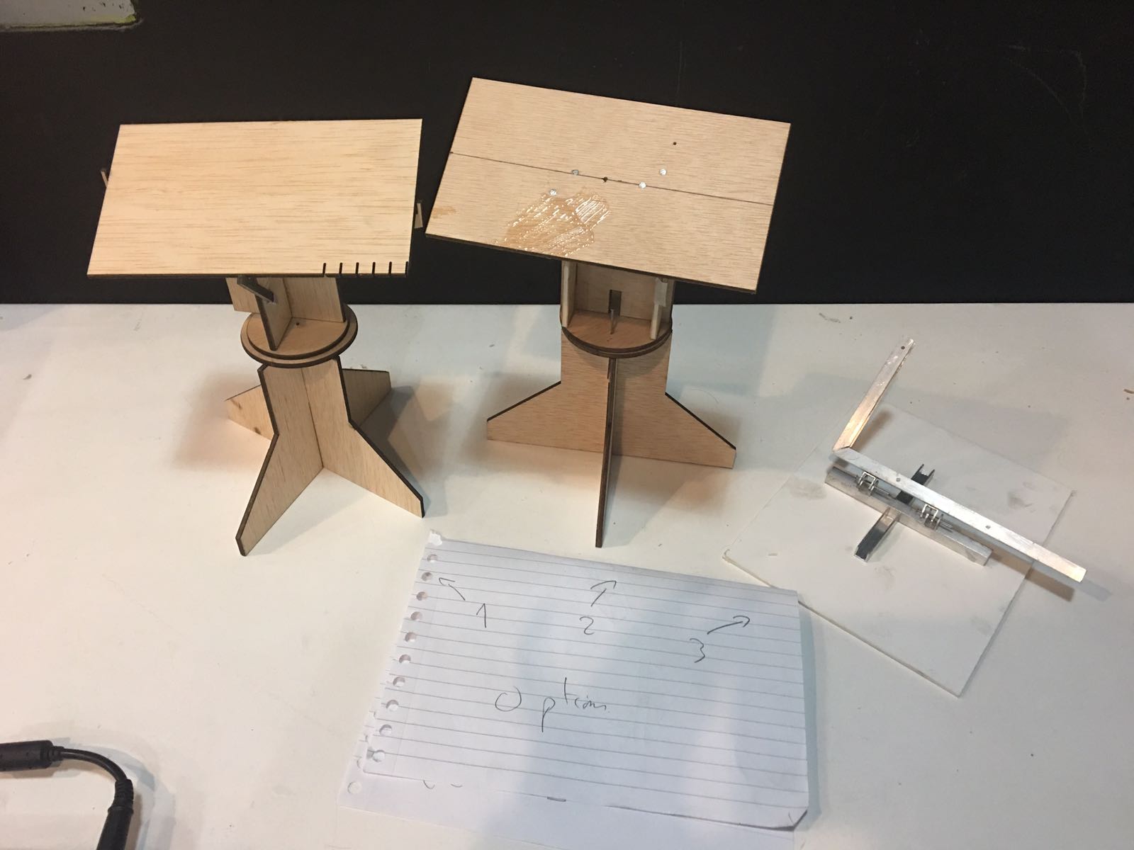
23rd March: Decision Making time: 4 mechanical options to choose from with different levels of complexity and weight and force constraints, with a lot of passionate debate :)
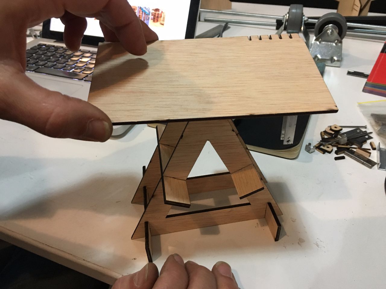
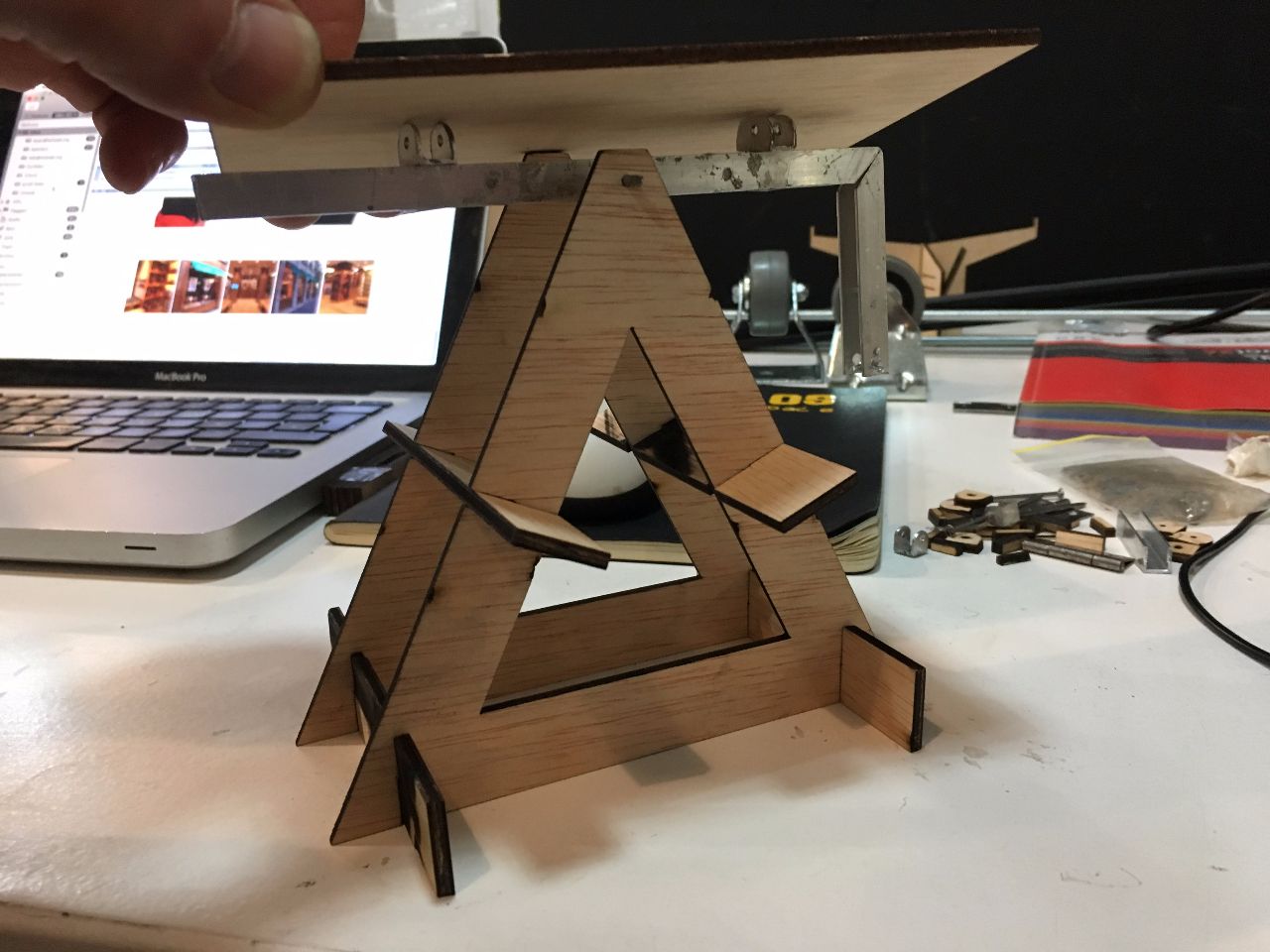
Small prototype
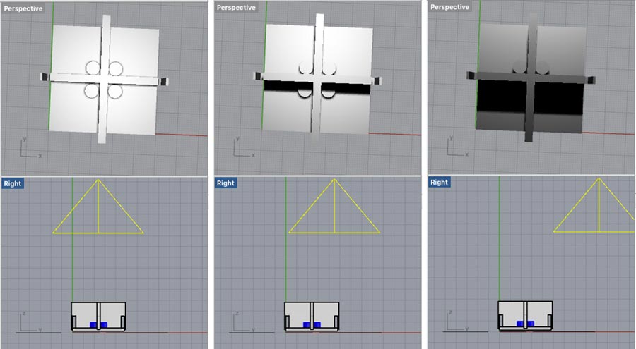
FIRST CONCEPTS Mechanical Design 3D:
.png)
.png)
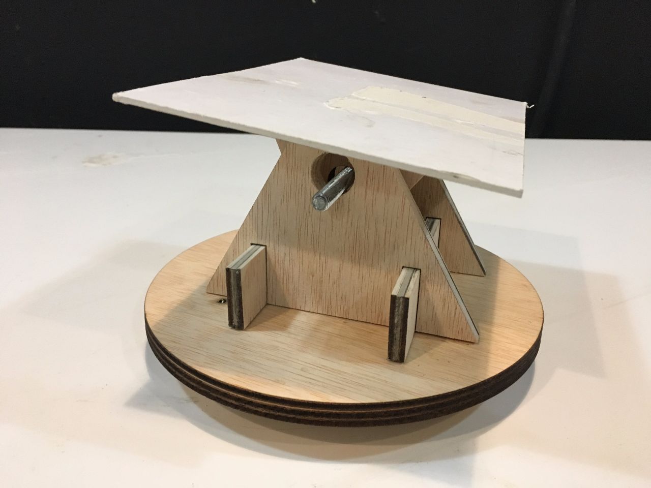
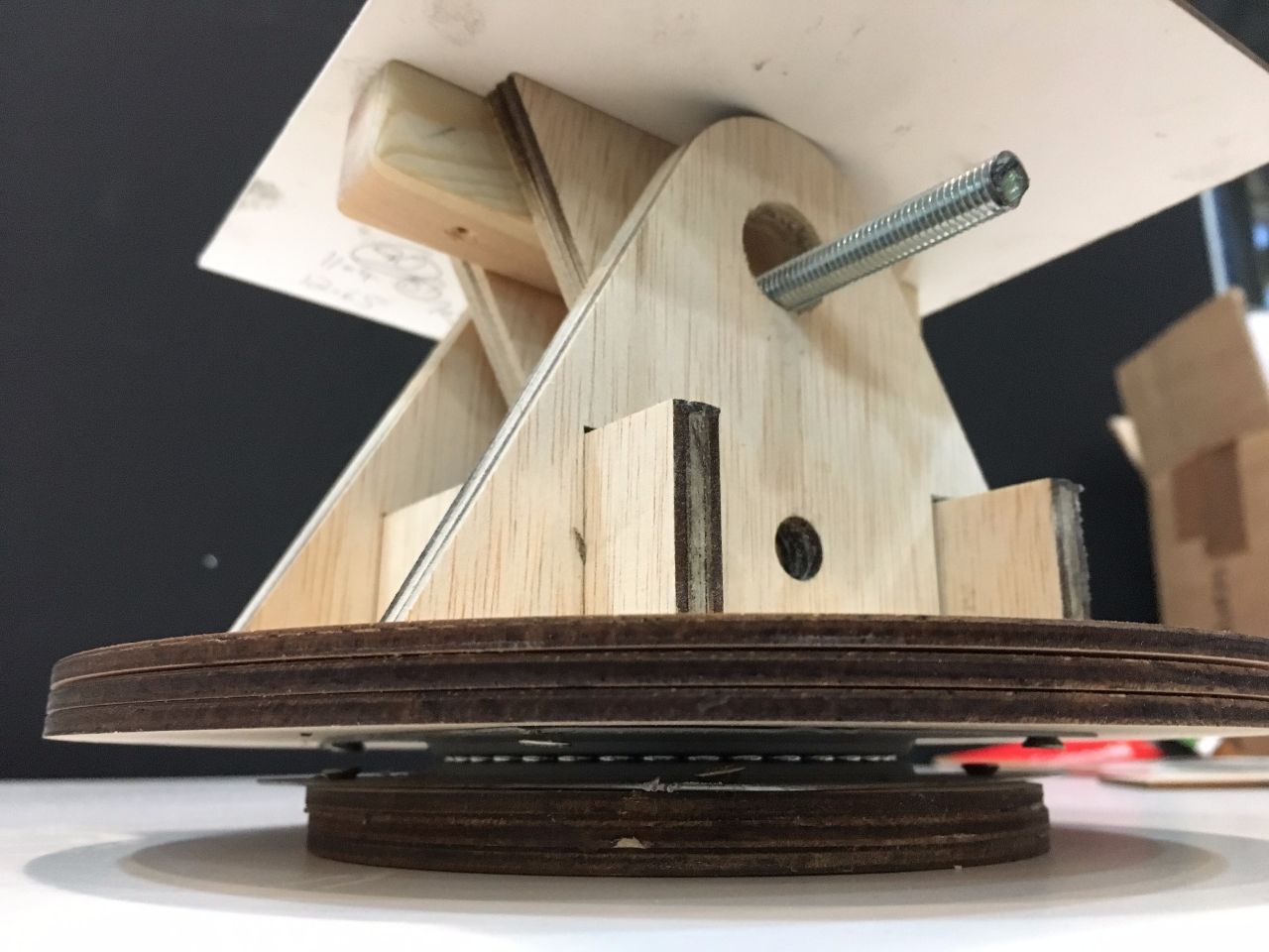
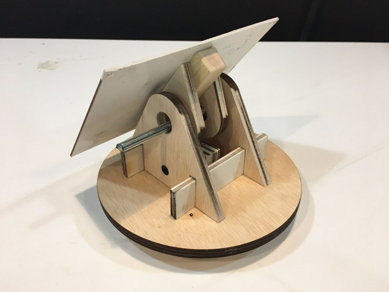
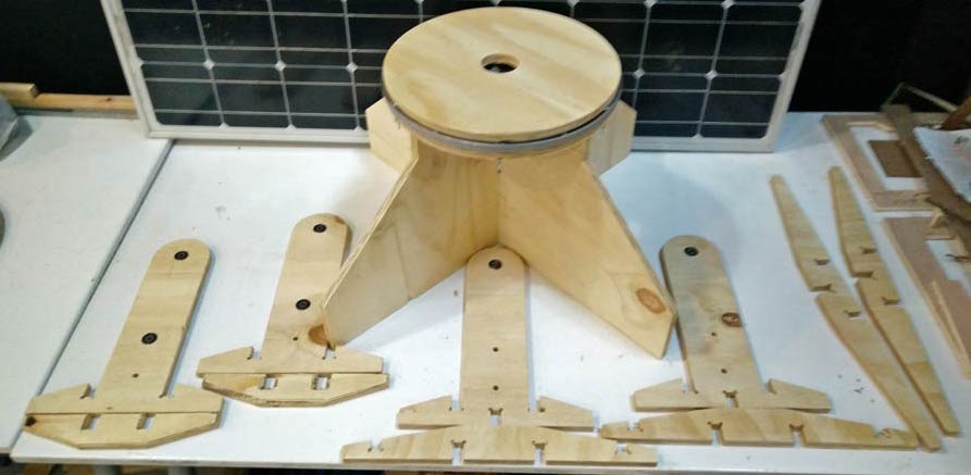
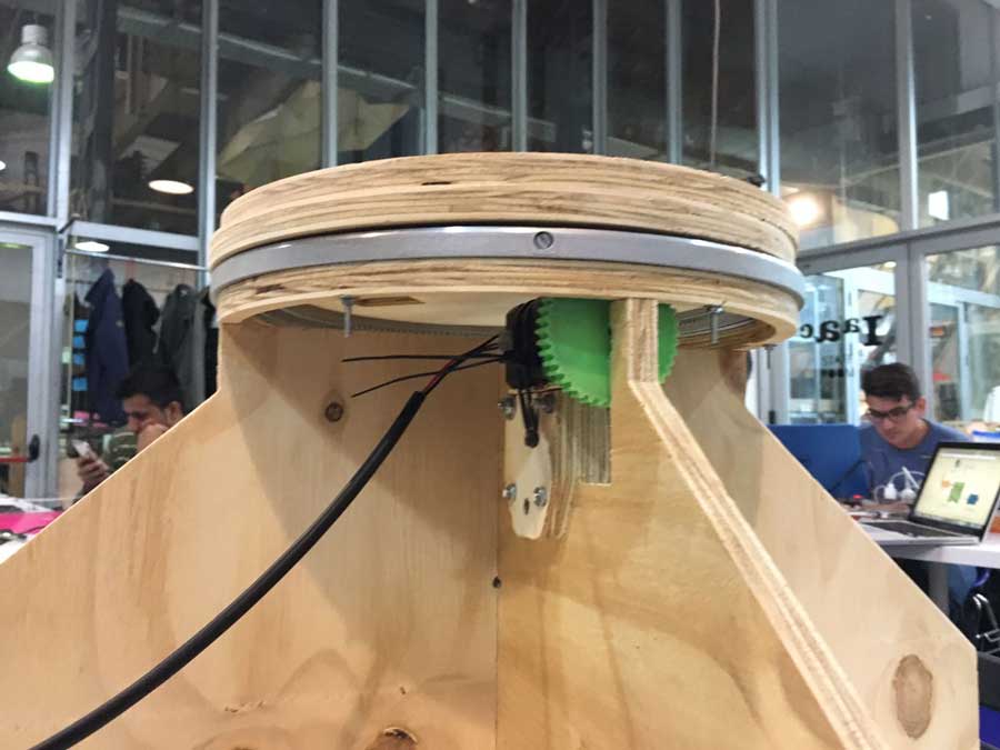
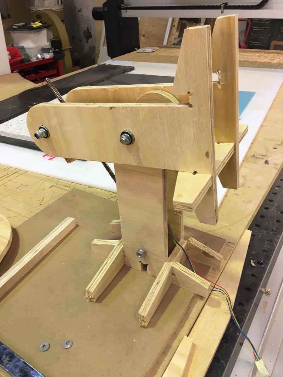
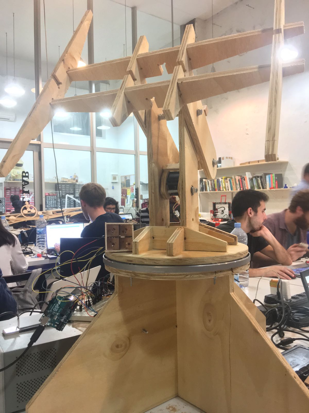
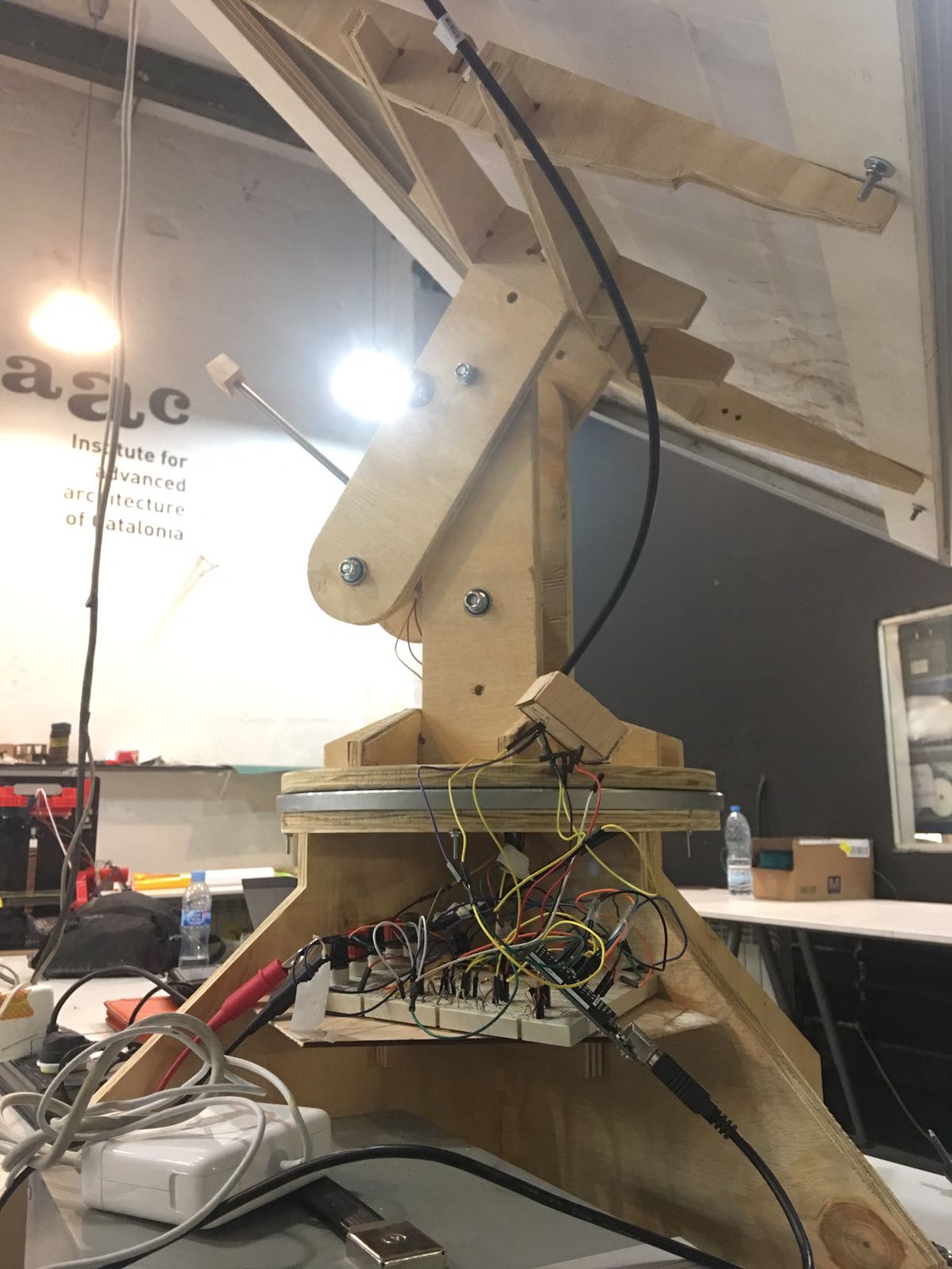
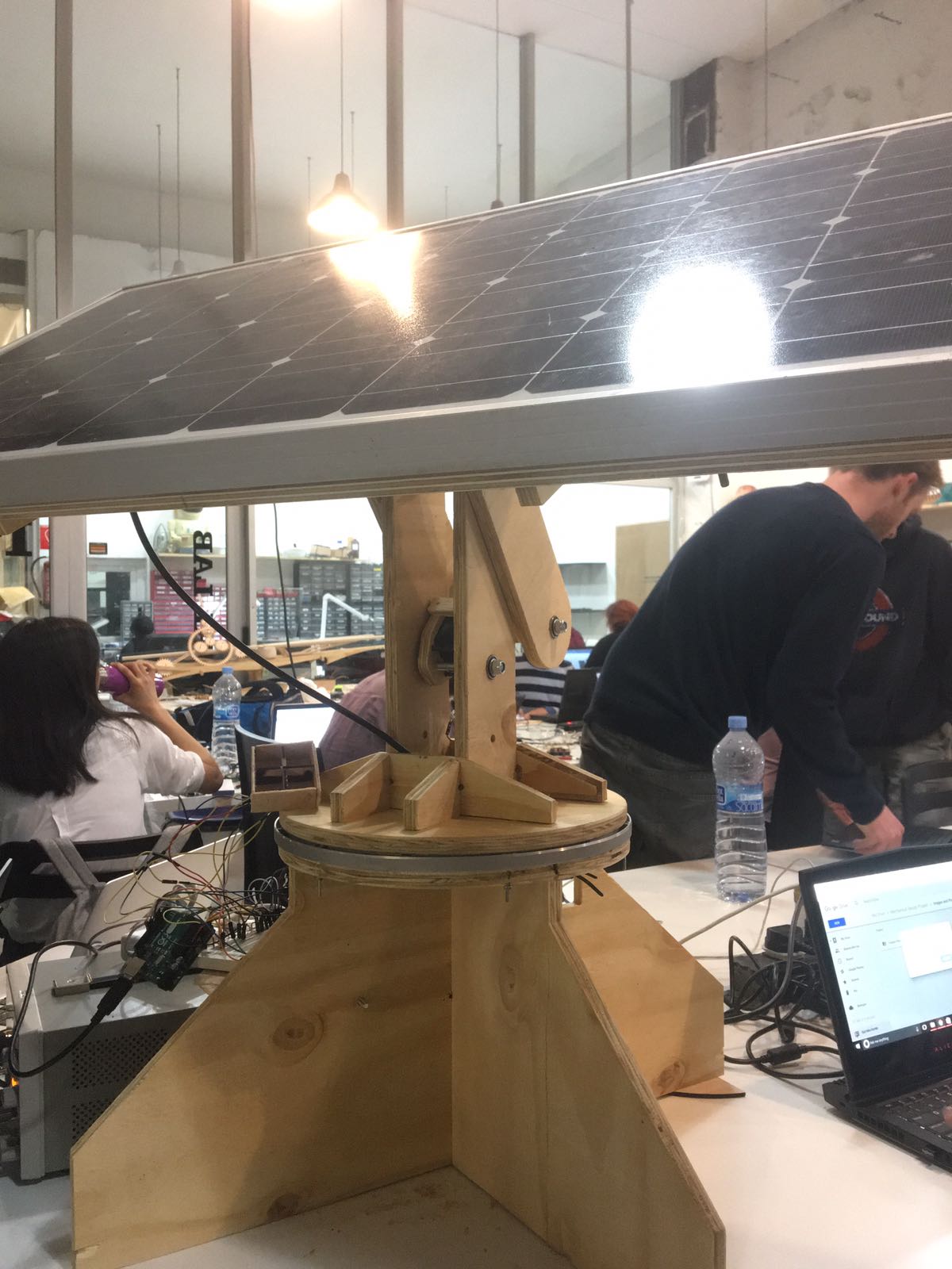
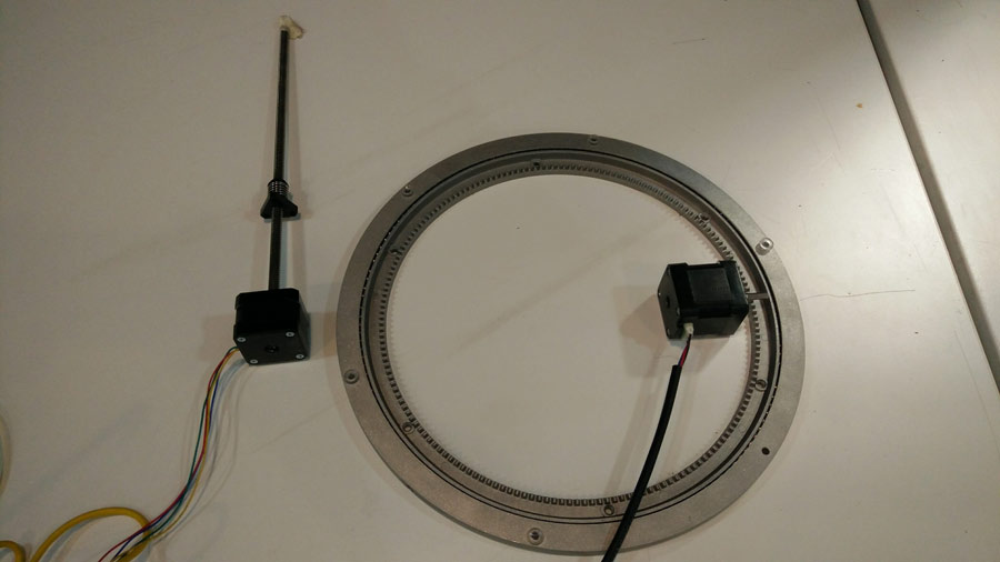
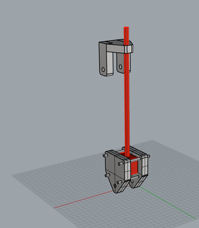
At last we iterated a final design from the diferent options we had considered. It will be fabricated with 15mm plywood and uses one direct and one linear actuator. The pan movement will operate through a swivel system integrating a lazy susan. And the tilt will operate with a linear step motor attached at one end to the base and the other end to the moving part (where the solar panel is attached).

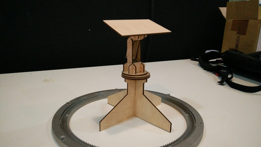
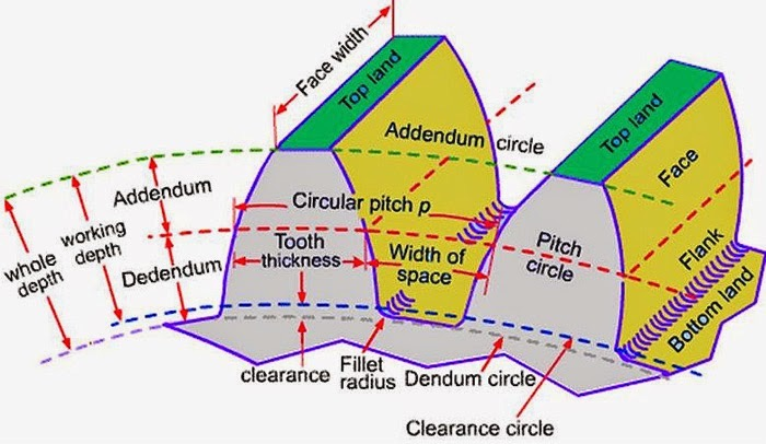
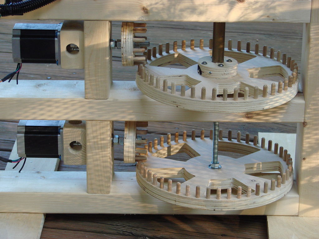
Geared Rotating Turn-table - TeethProfile
We are designing and generate to couple with the gears from the lasy-susan.
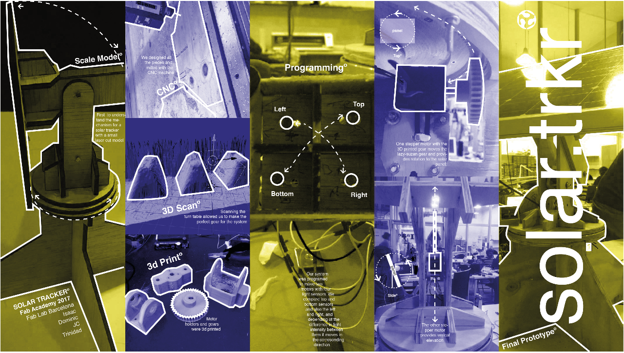
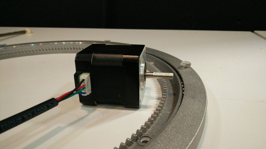
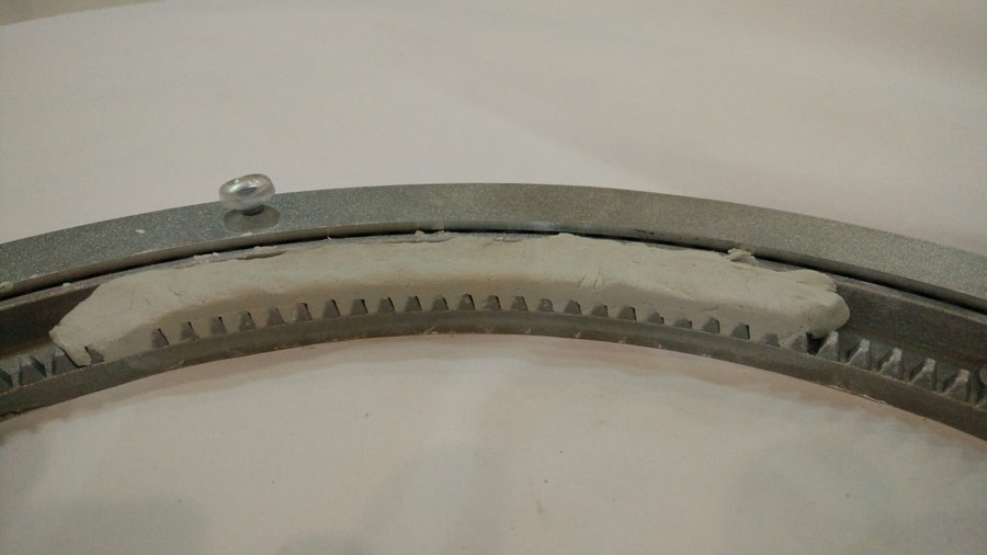
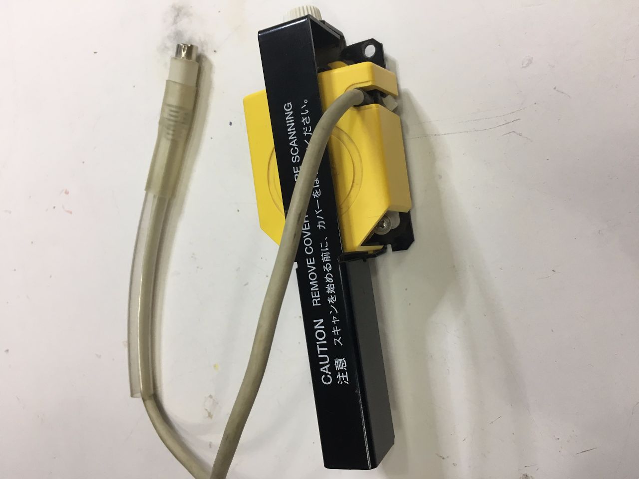
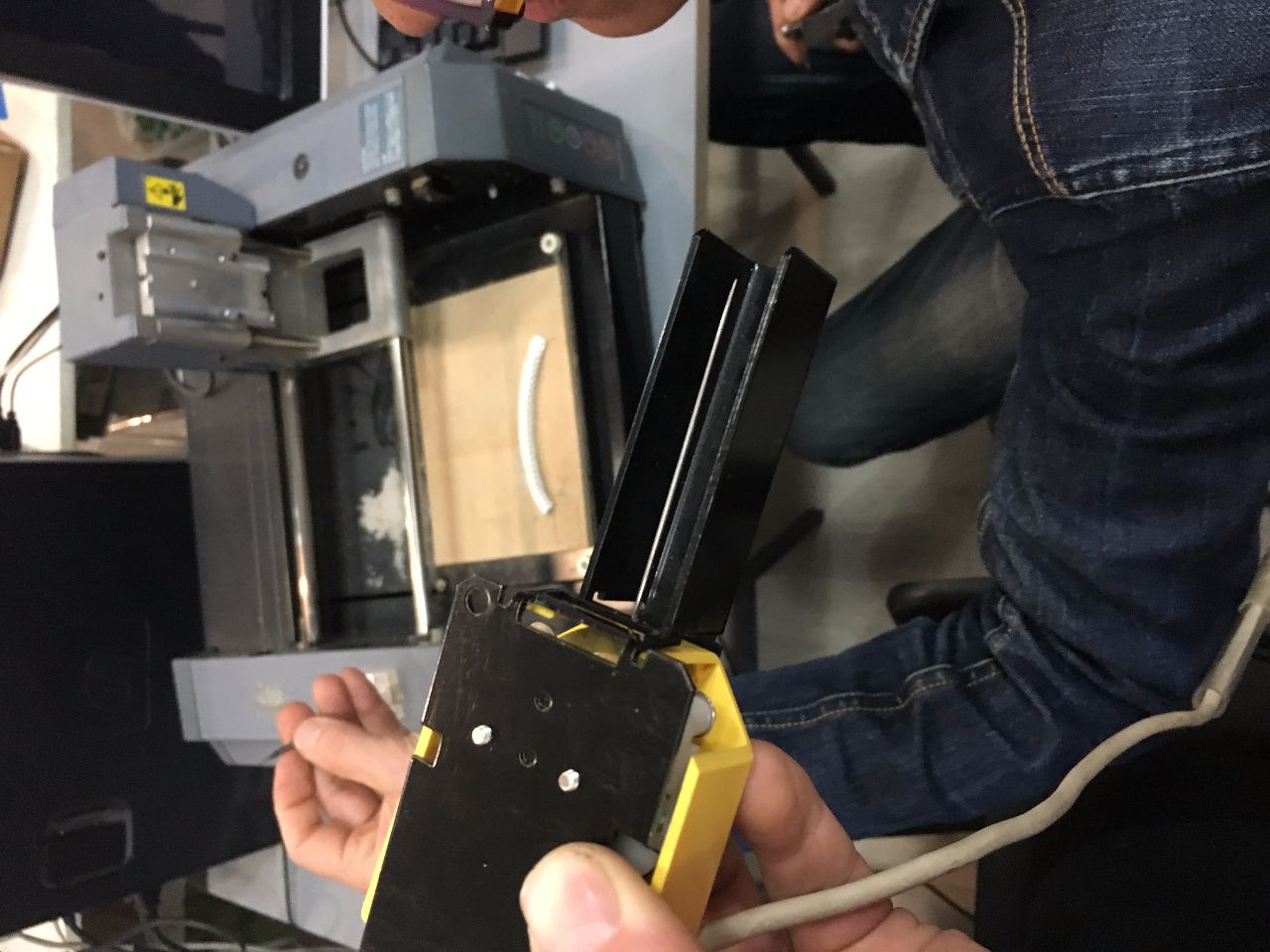
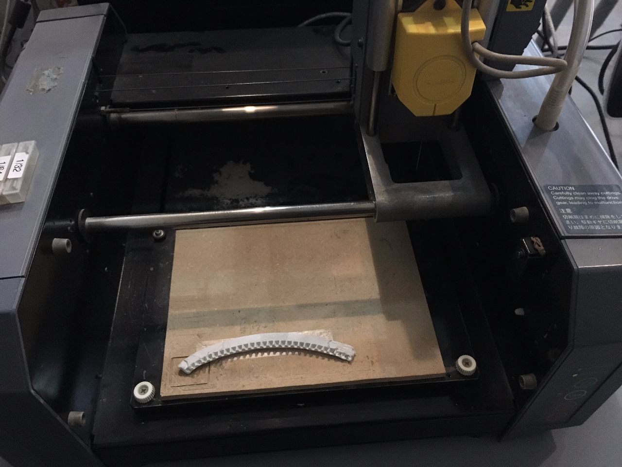
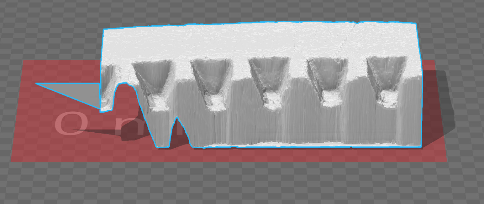
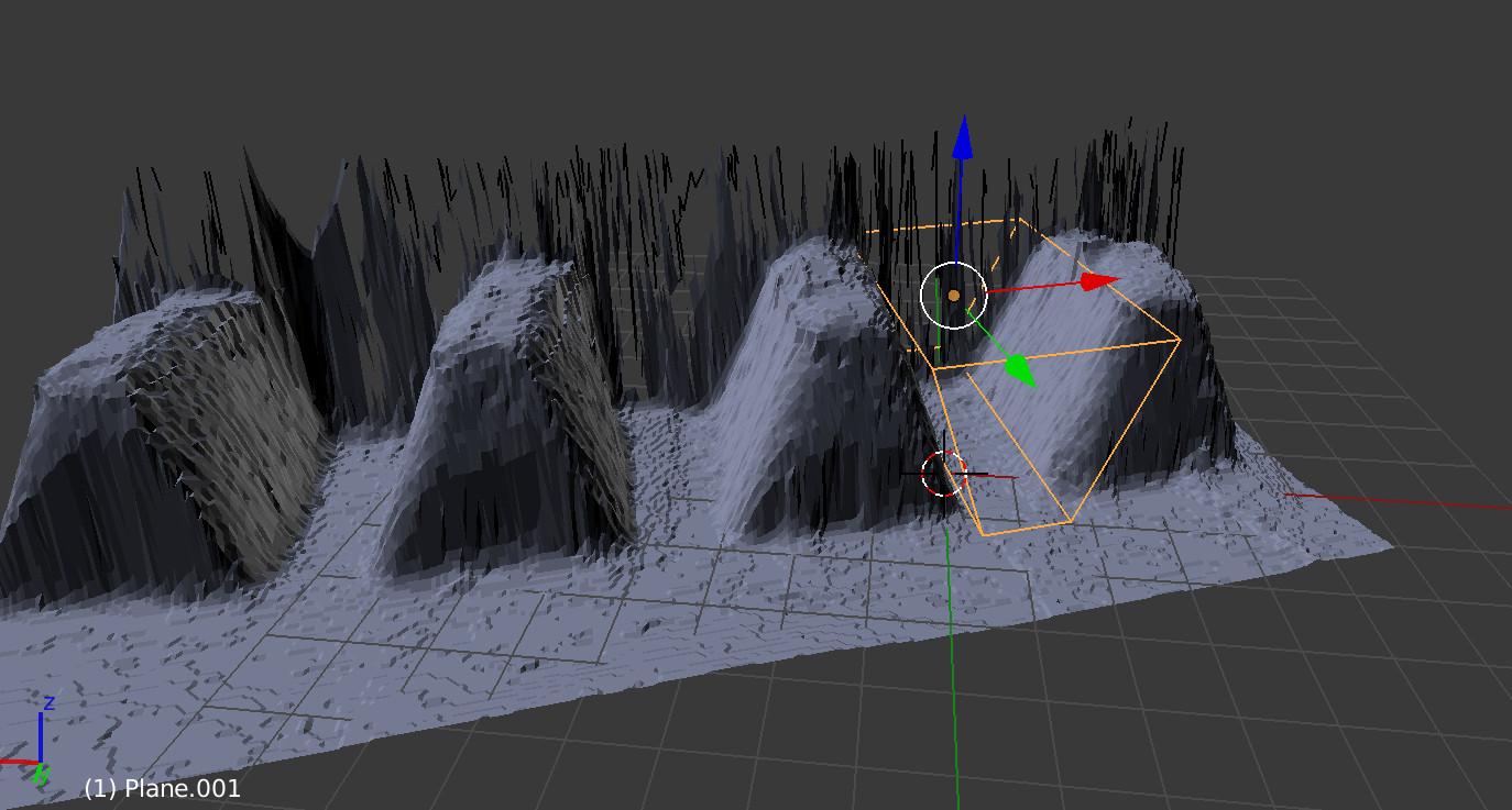
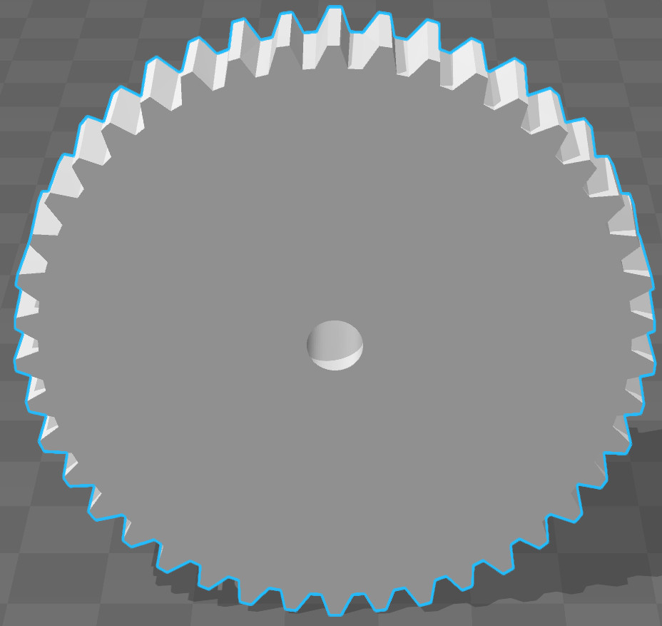
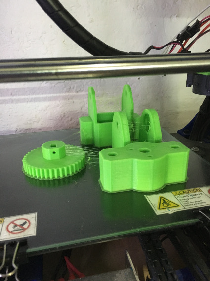
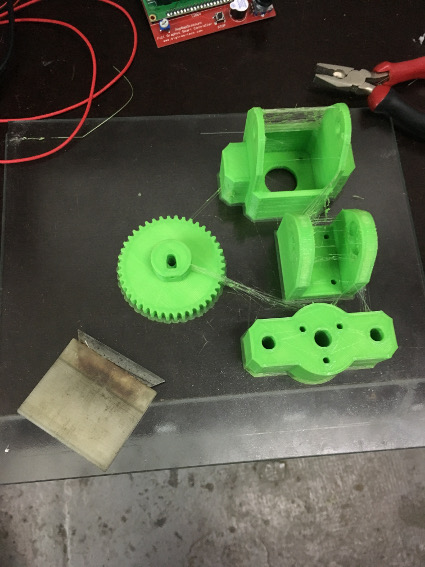
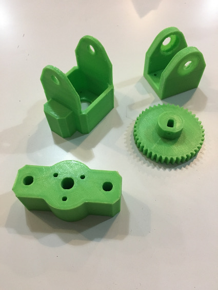
We used an online gear generator to come up with some test gears aproximating the tooth profile and trying a few iterations 3D printing them to find one that meshed correctly with the teeth profile of the ’lazy suzan’. We needed to make a better fit and mesh for this gear, as it will be moving all the weight of the solar panel and frame above the platform. We decided to make a mould of the teeth with a "plastiline" (children putty). We let the casted teeth dry slightly before before scanning it with the Modela 3D scanning device.
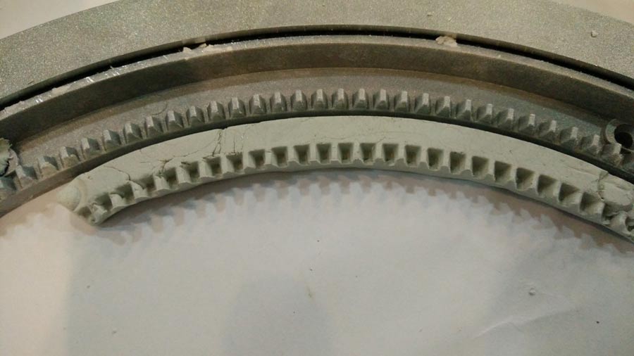
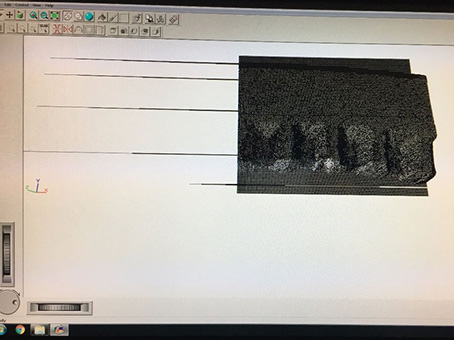
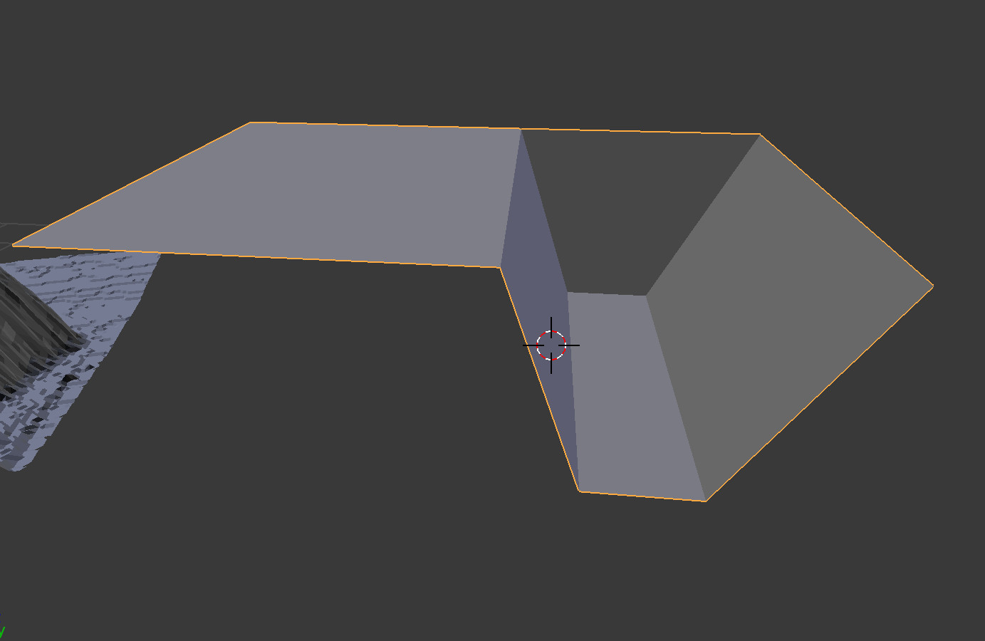
The scan result is STL file containing a point based mesh that we saved and then exported into Blender. We had some help using blender from Victor who knows his stuff in this program. It was apparent that the scan couldn’t easily be cleaned and shaped into flat surfaces so we re-model a section of a couple of teeth from this profile making a positive form to use. Then we rotated this section in a polar manner around a circle to create our solid test gear part. Adding manifold edges and a grub screw fixing for the axle attachment.

This was then 3D printed along with some motor mount casings we had designed to hold the two motors. The tilt/elevatiom motor would have to allow for rotational fixing.
Two ways to program stepper motors

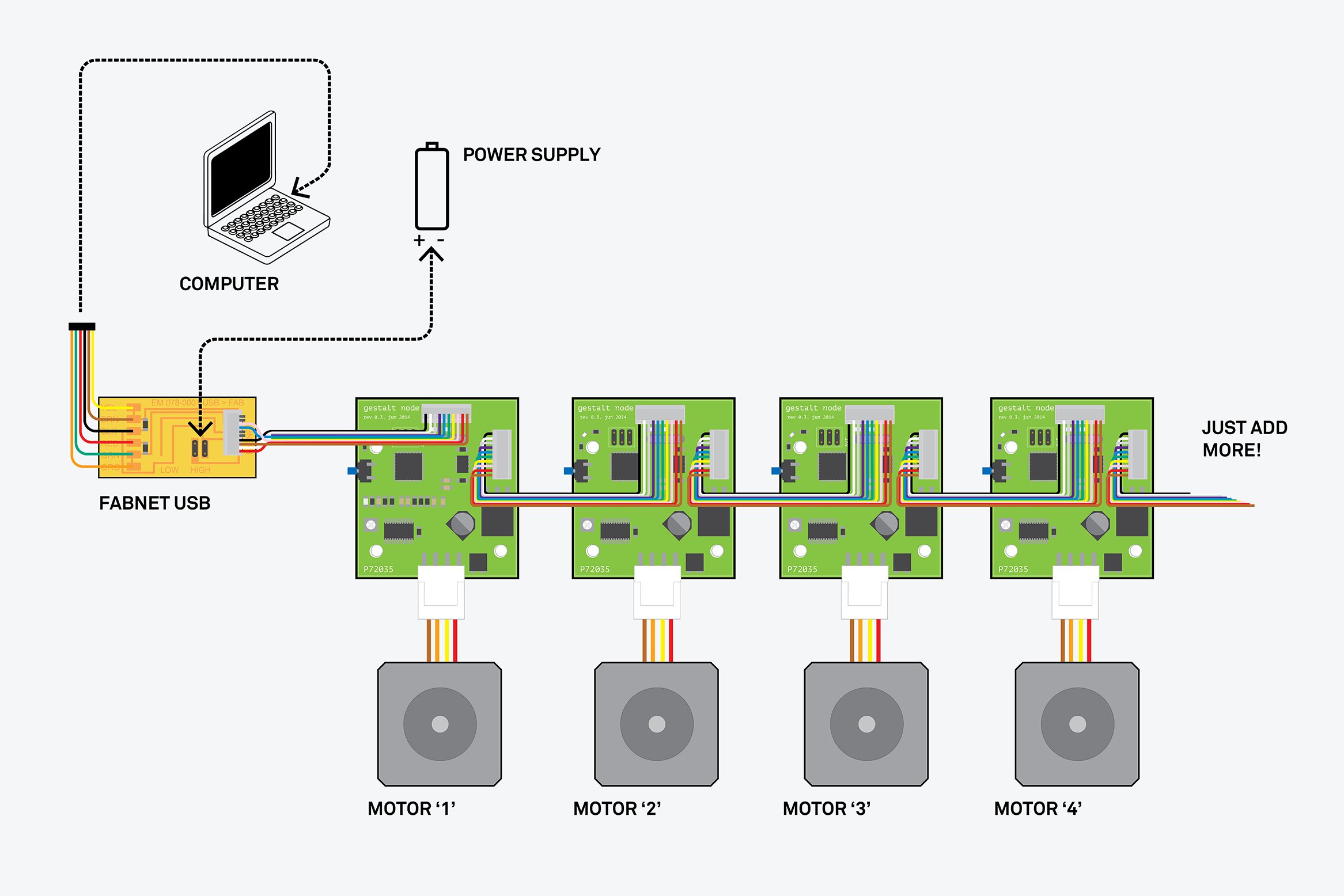
Getting Started With Gestalt Nodes
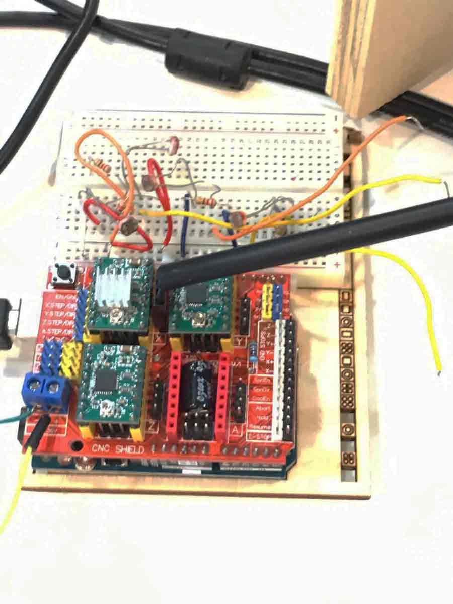
Programming Stepper motors with Arduino + CNC Shield
Hardware
Arduino
CNC Shield
Pololu Drivers
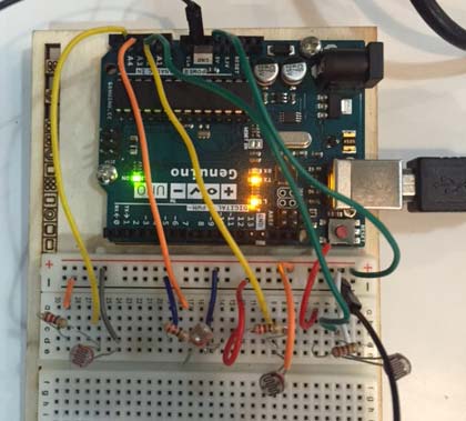
Testing out the light sensor with Arduino
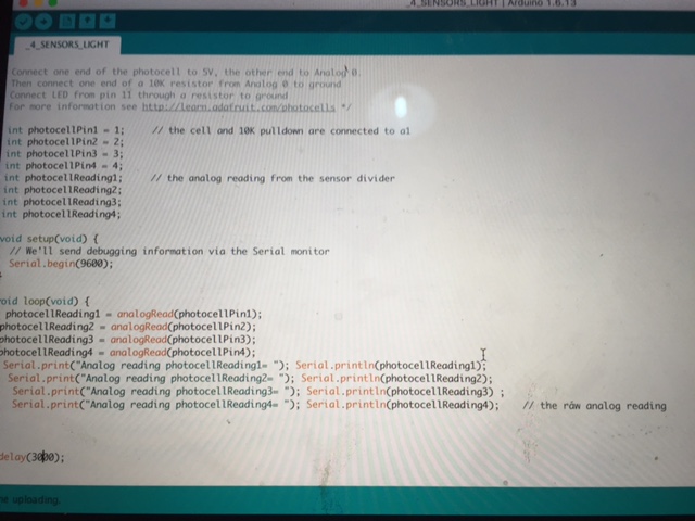
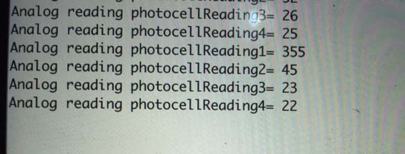
Following some tutorials http://www.instructables.com/answers/Multiple-Photocell-Problem-Arduino/, and adjusting the code in Sketch we could capture light data for each sensor.
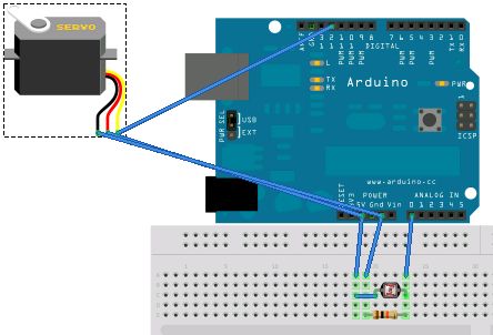
Moving Servomotors with light sensor
Link to Arduino Sketchs
Simple Analog reading of the 4 photocells click here
Final program
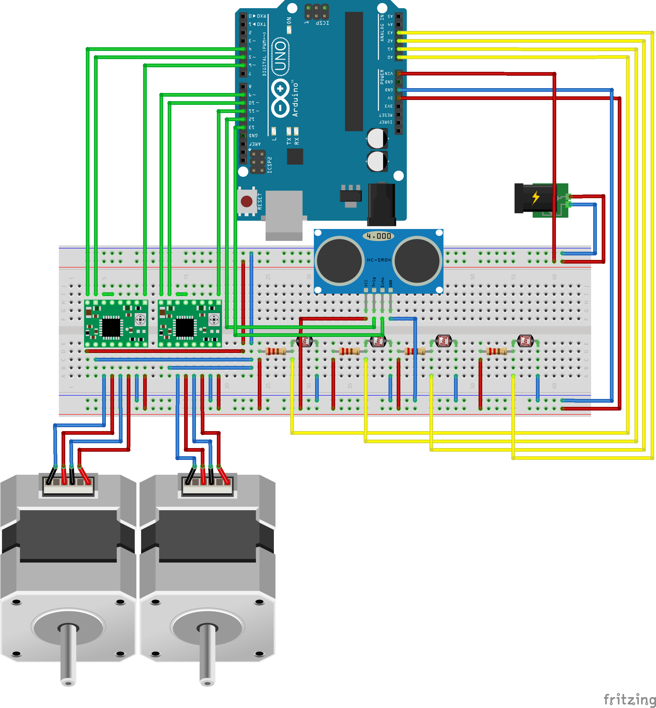
First we connected two stepper motors
Here you can find attached the link that we follow to connect the two stepper motors with the arduino (Two stepper motor instructable)

In the right side you can find the two pololus drivers attached to the breadboard, this side is connected to the 12V. There is 2 pololu driver, one for each motor - that is one for the rotatory/swivel movement and another for the pan movement.
Our final circuit for our Solar Panel
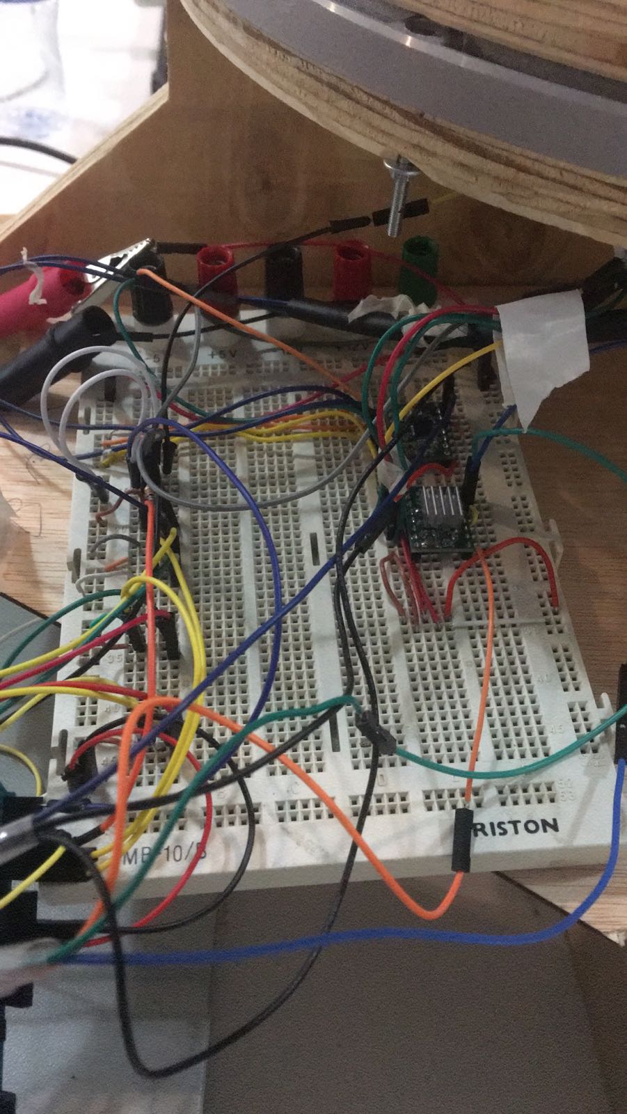
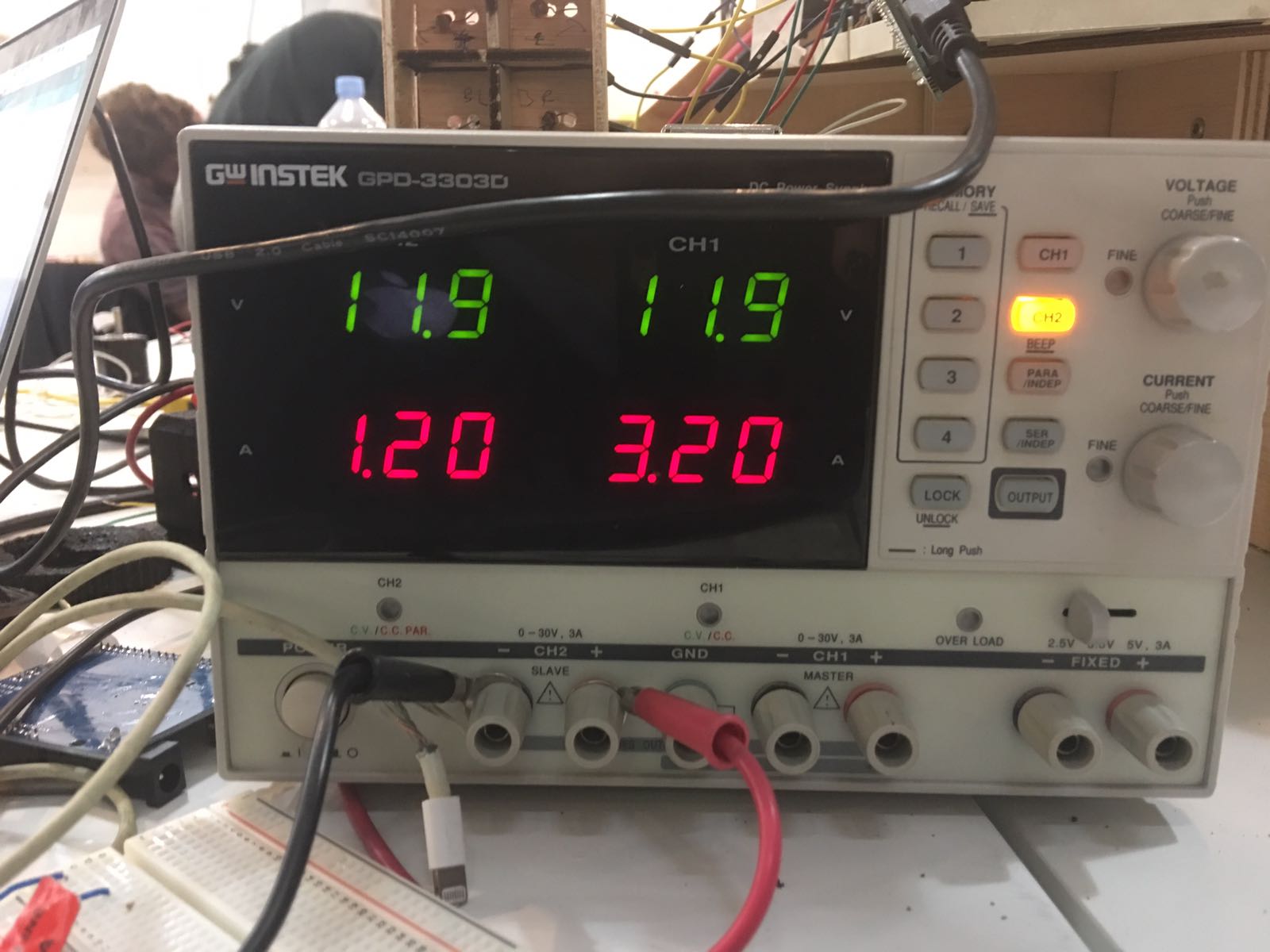
12v source power
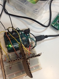
In the left side we connected the four light sensors with 5v from the Arduino and we place them in a small container that is going to be in the top of the Solar panel. After programed the two motors, we programmed to respond to 4 light sensors signals.
FAQ Programming
The motors seems to have power but do not run ! What shoud I do?
There are 3 factors you should play until you find the correct settings for the gear and weight of the machine:
delay(2000); Serial.println("goes down");
for(x = 0; x < 40; x++) // Loop 200 times
{
digitalWrite(10,LOW); // Set Enable low
digitalWrite(8,HIGH); // Set Dir high
digitalWrite(9,HIGH); // Output high
delay(10); // Wait
digitalWrite(9,LOW); // Output low
delay(10); // Wait
The motors dont run anymore. What is the way to solve?
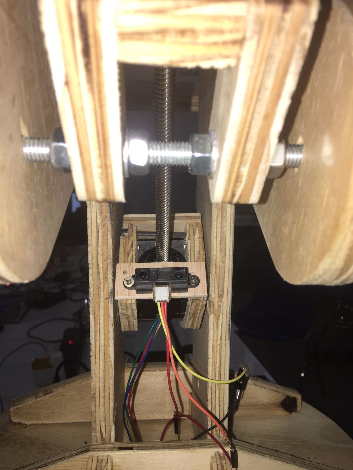
Why do you use distance sensor for your machine?
Because of the arduino code we are using (which was the best one for running our motors and moving the machine), we dont use Gcode or coordinate, hence it is impossible for the machine to know where it is.
The Solution: for the up and down motor, we had to find a way to tell it to stop going up or down at some point, so we use a distance sensor, to tell the up and down motor to stop running in one direction or the other if there was a risk of collision or loss of our machines pieces.
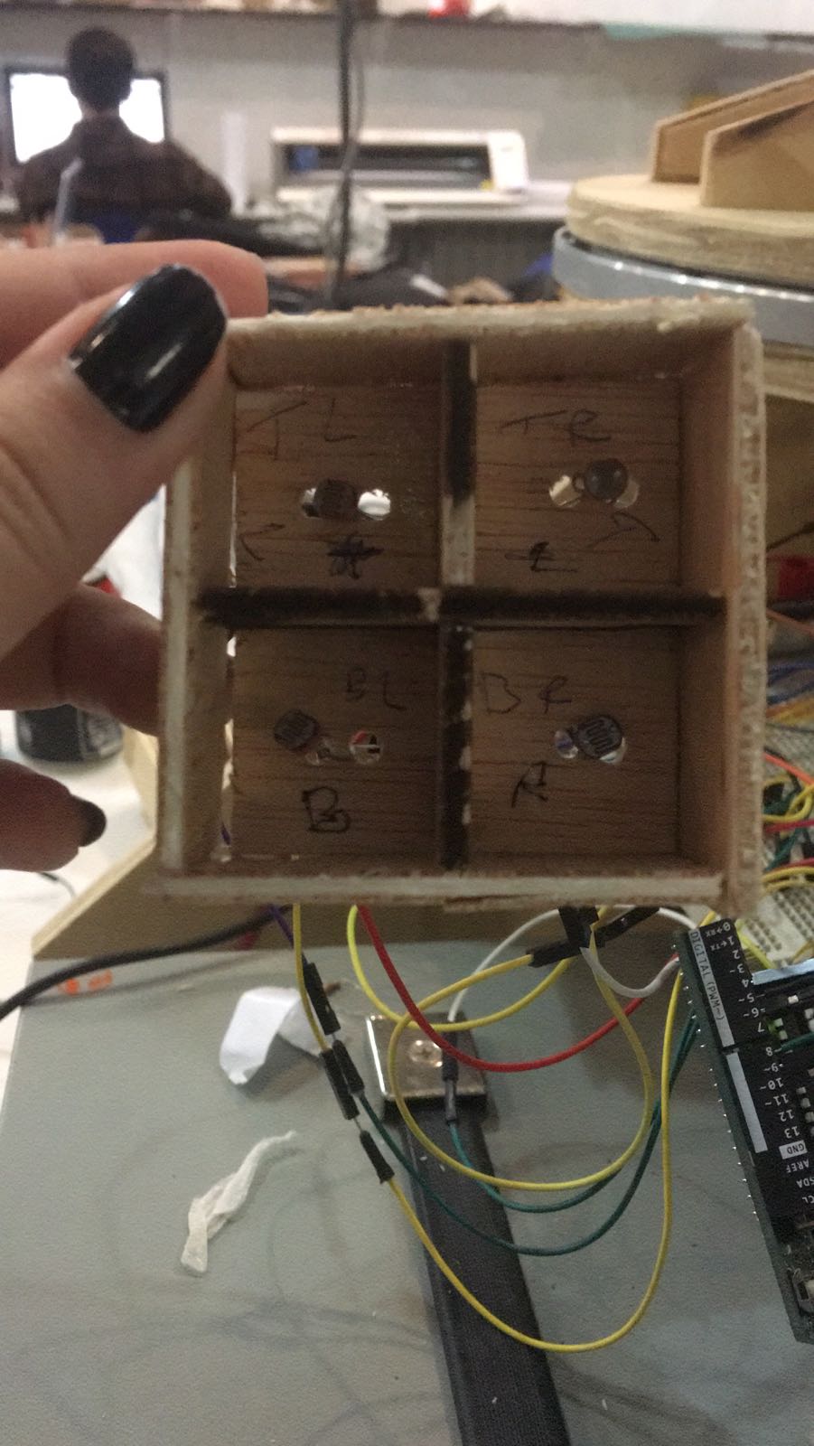

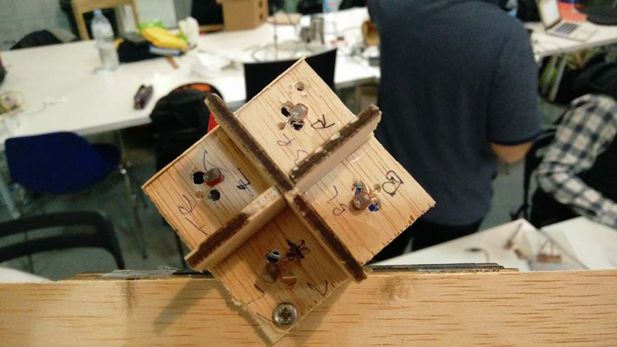
After testing with this box we realized there was not enough intensity difference between each sensors. and for that reason the motor would not respond properly. So we took the exterior walls of the box out and brought the sensors closer to the center and the separation walls. This way we can be a lot more precise in measuring the light reaching each sensors - and consequently program movements to change the orientation of the panel towards the sun.
We also added a distance sensor as a stopper for the pan axis so motor turns off when the position reaches limits of the movement allowed by the machine - avoiding stress on the mechanical part.
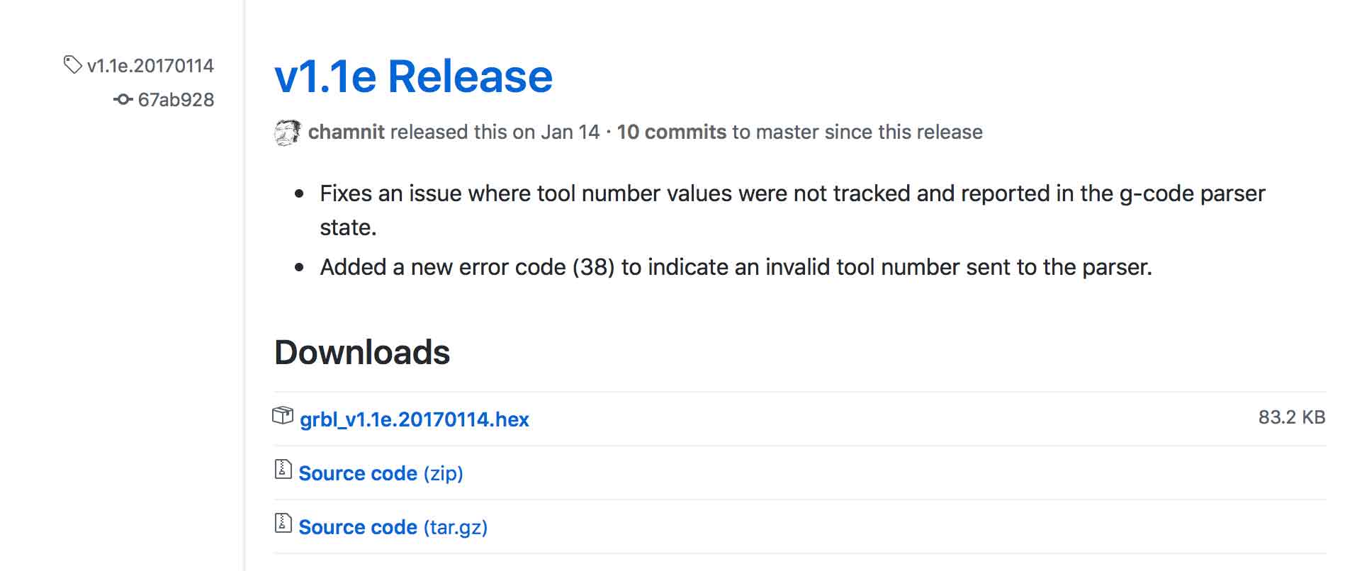
Download the Source Code (ZiP)
https://github.com/gnea/grbl/releases
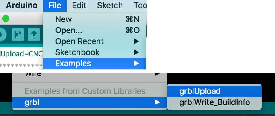
Install GRBL as a library in Arduino
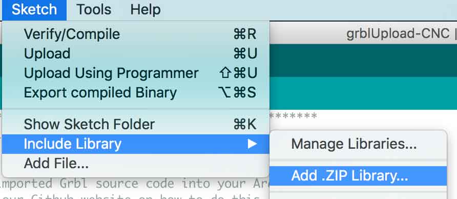
Load grblUpload into your Arduino board
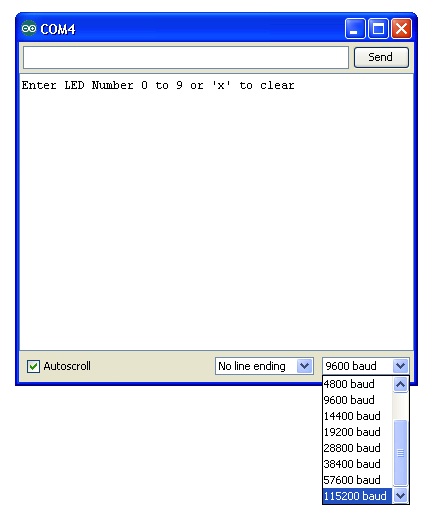
Warning: Make sure you change the baud rate in the sketch from 9600 to 115200 and upload it to the board again.
Warning: changing baudrate back and forth in arduino made my USB port connection to Arduino from the Mac to stop working (more info on the issue). Installing the FDTI drive from the website solved the issue.
Make the 3 motors move
Once the Sketch is loaded (Make sure the Arduino board, CNC Shield are powered with 12V), Open Serial monitor in the sketch and enter coordinate you want the 3 motors to go to
"X20.0 Y20.0 Z10.0" & click Send (or enter)
motor for X will go coordinate X, Y to 20, and Z to 10 in this example.
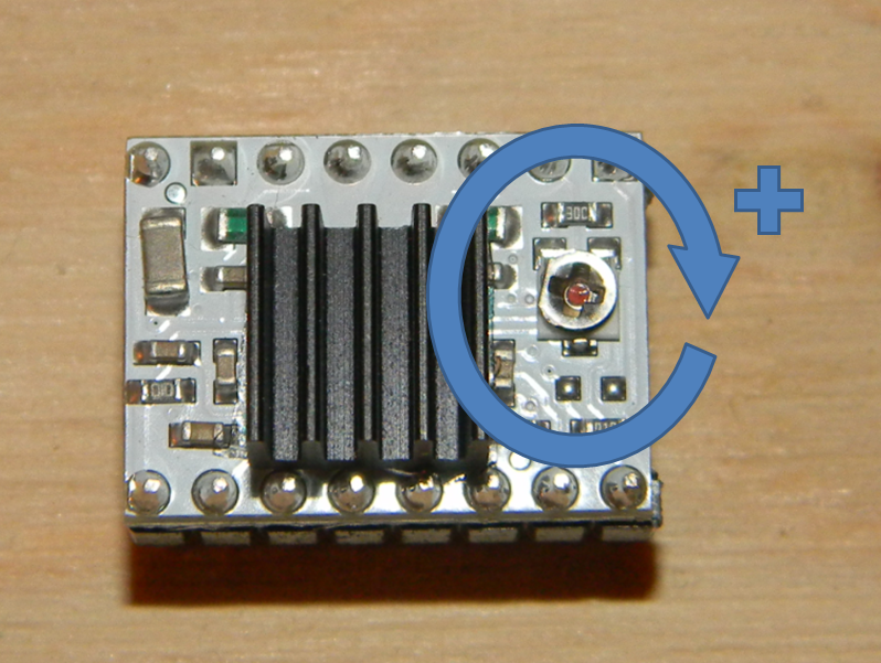
Warning: you may need to adjust potentiometers on the stepper driver for each motor to ensure adequate current is delivered to each motor.
To make the motor move again, change the coordinates to another locaiton, for example "X10.0 Y50.0 Z20.0" or switch off and back on the CNC shield.
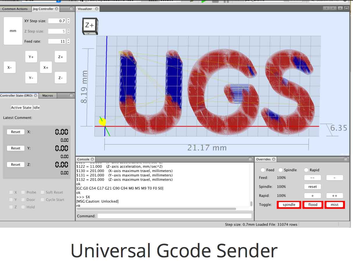
https://winder.github.io/ugs_website/download/
BILLS OF MATERIALS
https://www.pololu.com/product/2133 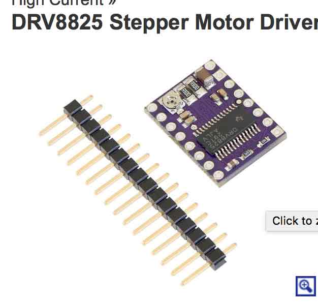
This breakout board for TI’s DRV8825 micro-stepping bipolar stepper motor driver features adjustable current limiting, over-current and over-temperature protection, and six micro-step resolutions (down to 1/32-step). It operates from 8.2 V to 45 V and can deliver up to approximately 1.5 A per phase without a heat sink or forced air flow (rated for up to 2.2 A per coil with sufficient additional cooling). The driver has a pin-out and interface that are nearly identical to those of our A4988 stepper motor driver carriers, so it can be used as a higher-performance drop-in replacement for those boards in many applications. This board ships with 0.1″ male header pins included but not soldered.
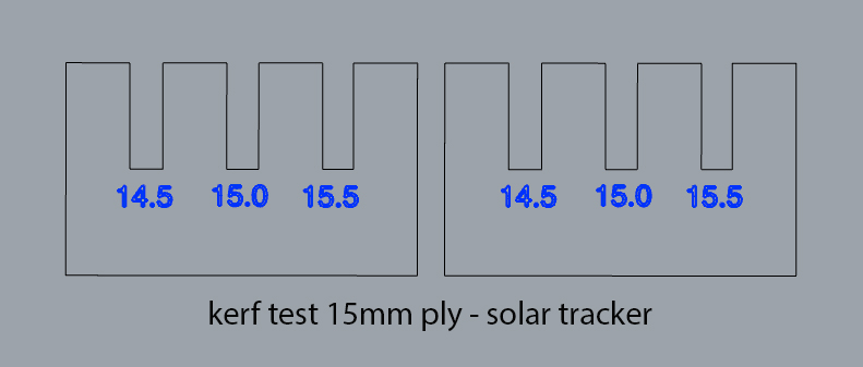
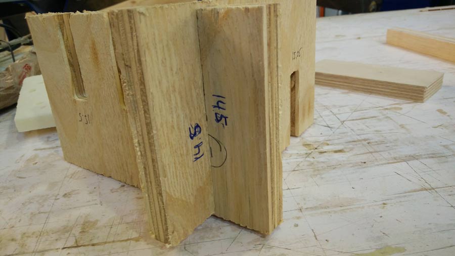
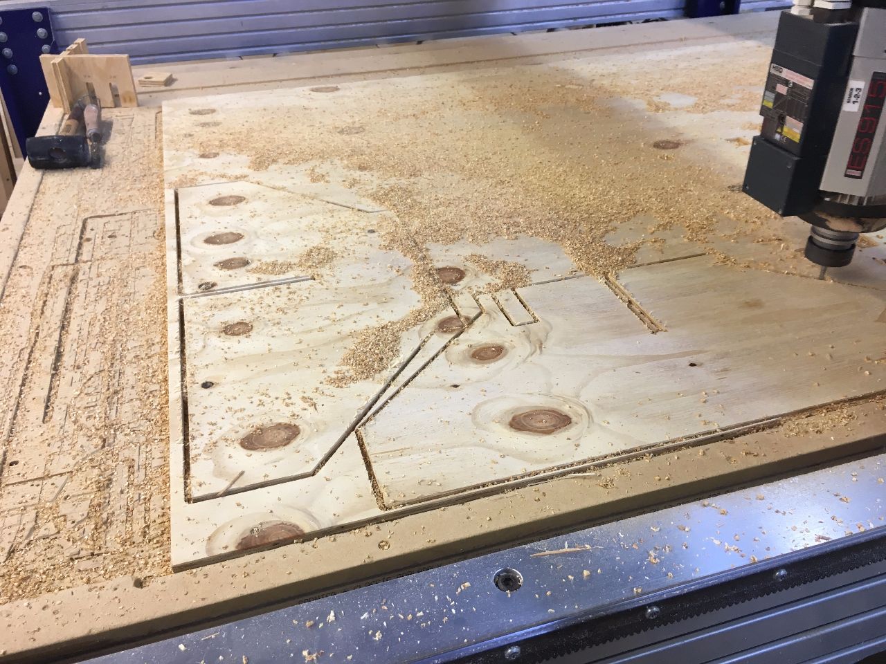
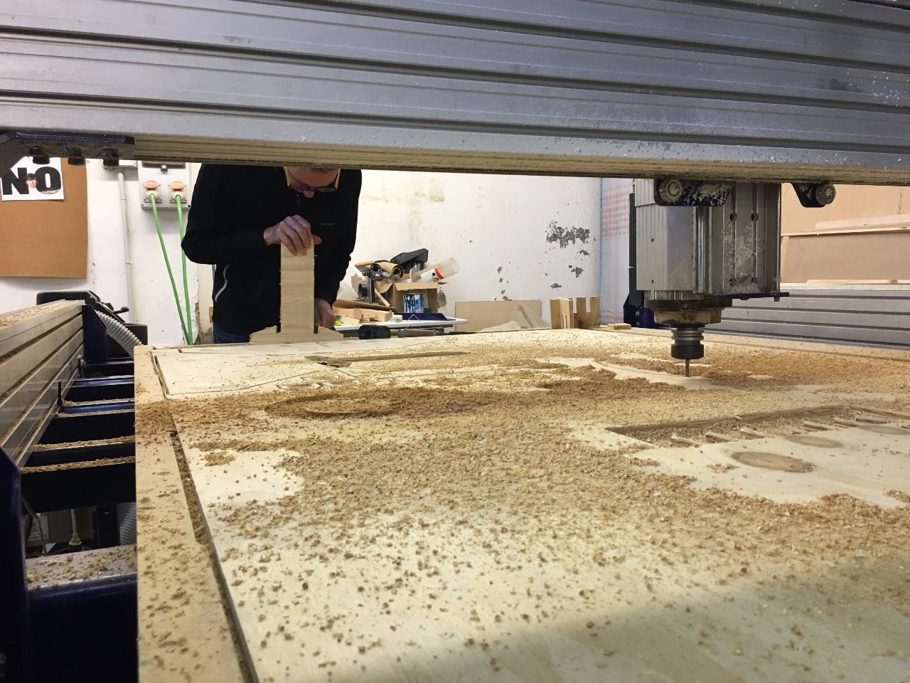
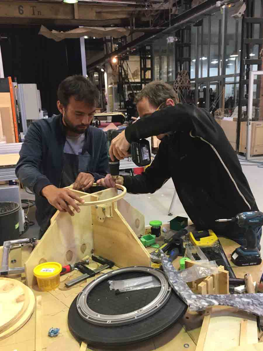
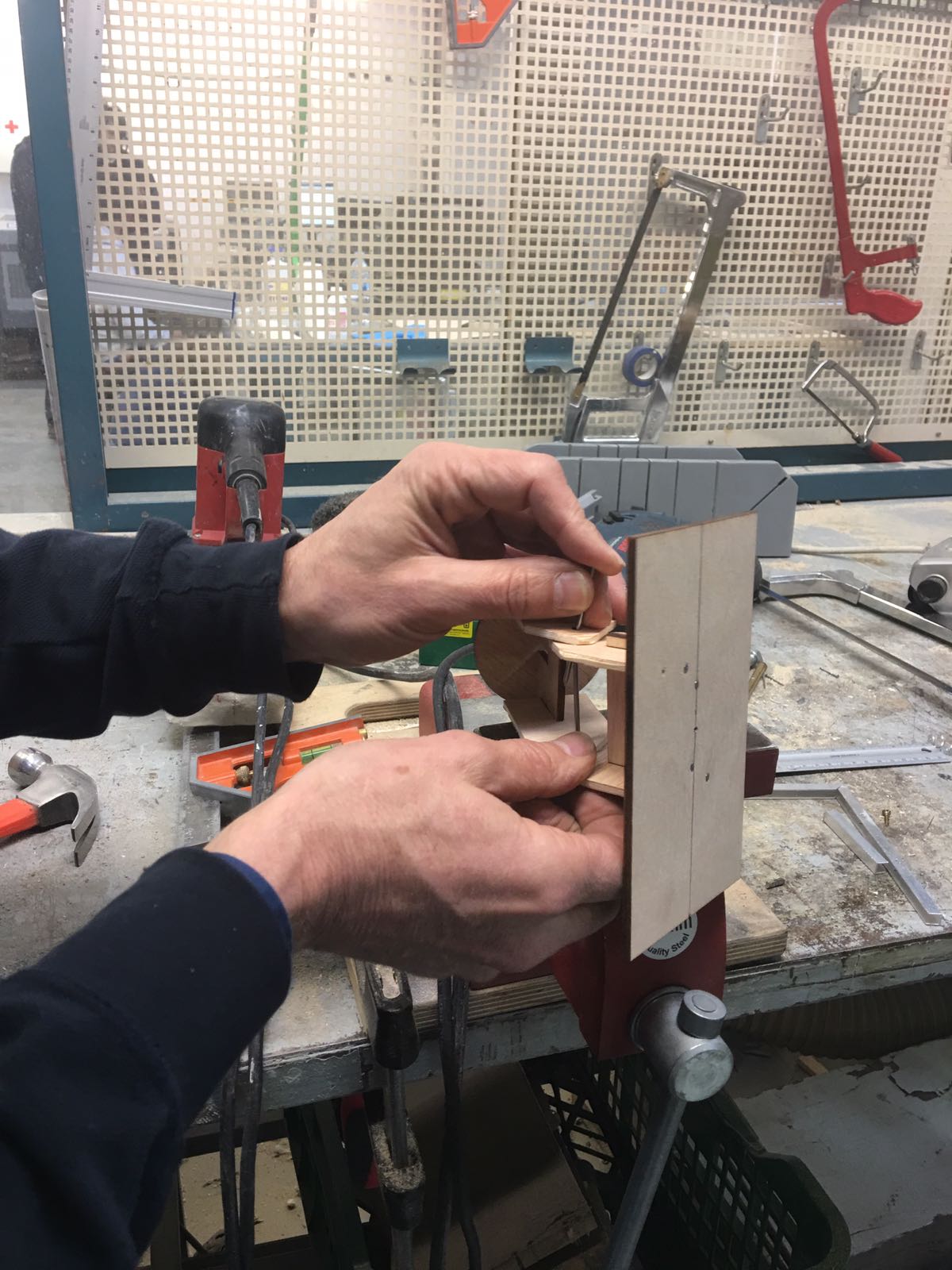
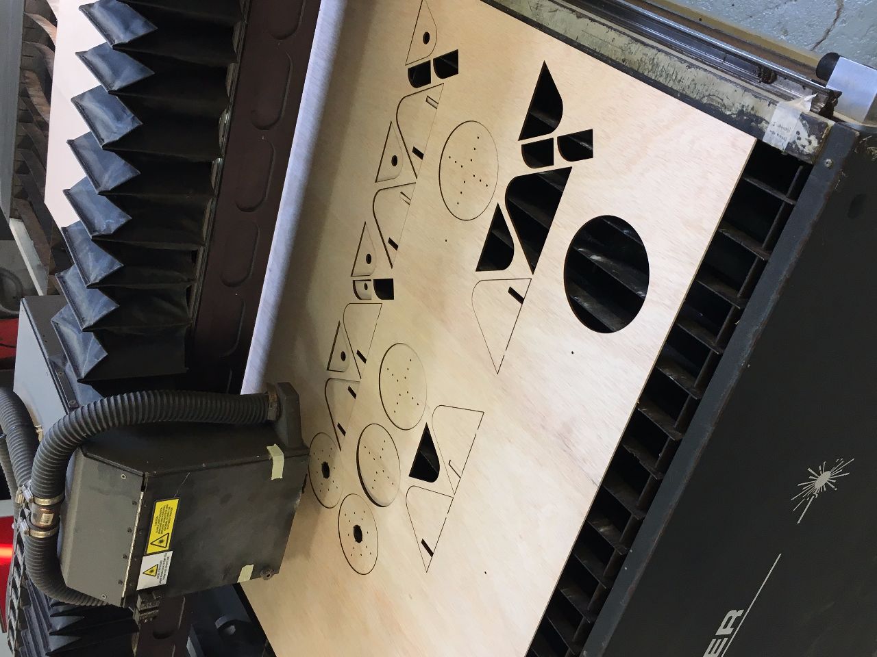
Prototype Progress - Milling the frame parts in 15mm ply.
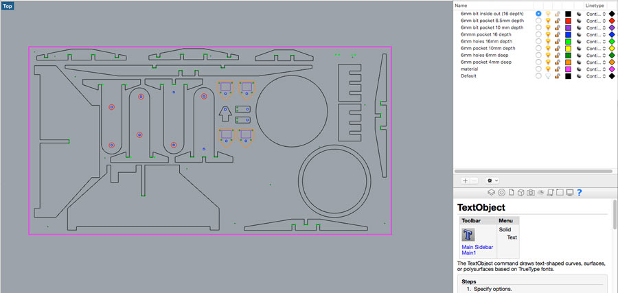
We did a kerf test for milling with 15mm low grade plywood.