Week18 : Project Development
The Main Parts
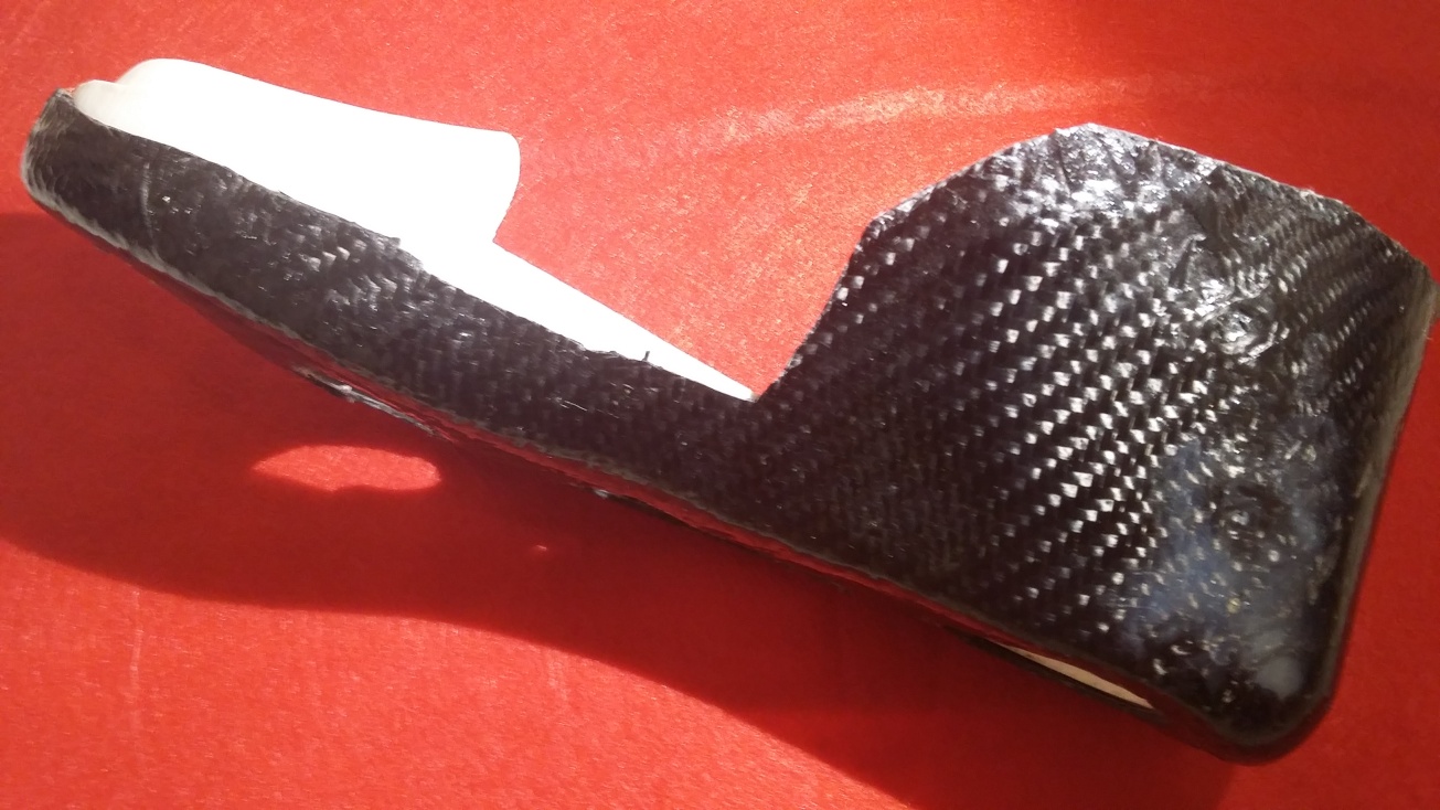
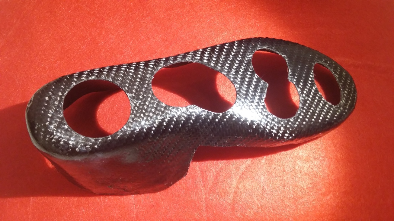
Upper Shoe
Is made out of a rigid composite to maintain the postiton of the foot and restrict the ankle joint. I chose carbon fiber as a light weight option. This would function as a typical POP(plaster of Paris) cast, with more flexibility in terms of ability of user to remove it. It would also function as a protective outer shell for the insensate foot to avoid further trauma and subsequent ulcers.
Lining
The lining would be made from a felt textile that would keep the feet worm, and enhance the blood circulation flow, diabetics have usually issues with small blood vessels. The choice of natural textile like wool is my preference but all depends on availability. But even synthetic felt would also be a good alternative. The lining can also function as a sensory layer in future enhancement of the project. This layer could also help prevent the crowding of toes in the shoe which might also lead to untoiced pressure ulcers.
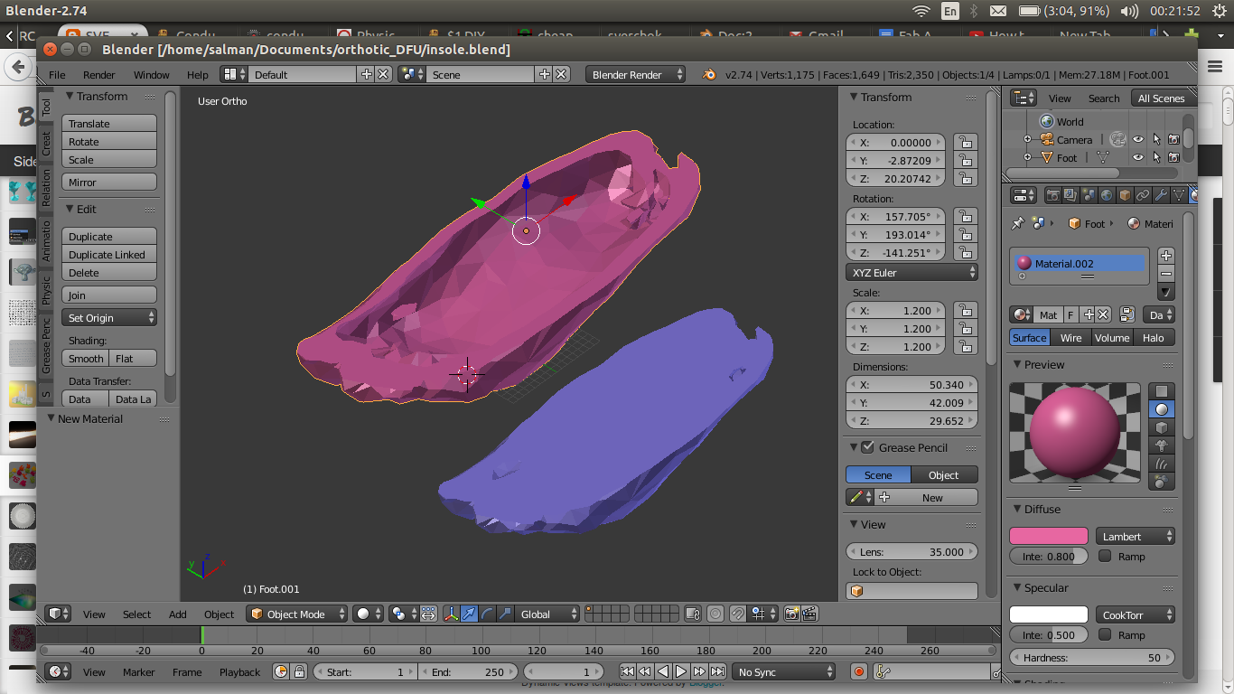
Insole
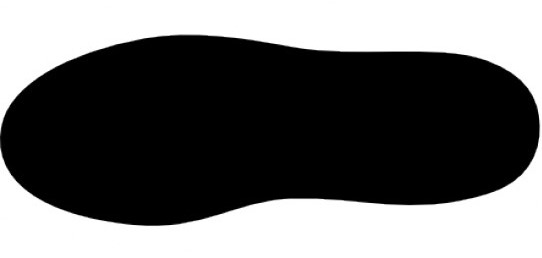
This is a customized layer made of the foot imprint in neutral non weight bearing position. I used 3D scanning as my method to capture the curveture of the insole to have a perfect fit to
Mid Sole
This is the planter sensory layer. I used two conductive textile layers of with VELOSTAT in between and flexible copper strips for the connections. Those are also enclosed in a two layers of felt. Outsole
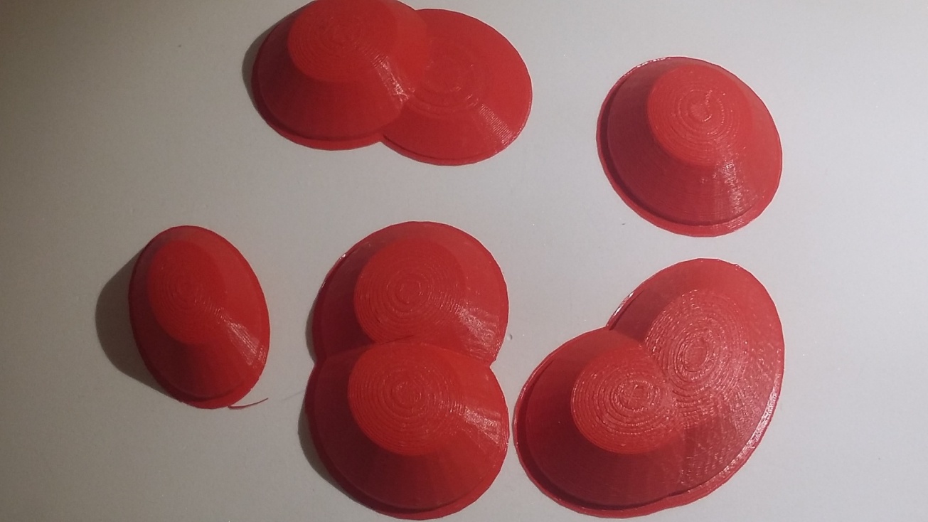
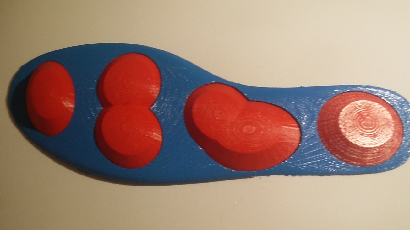
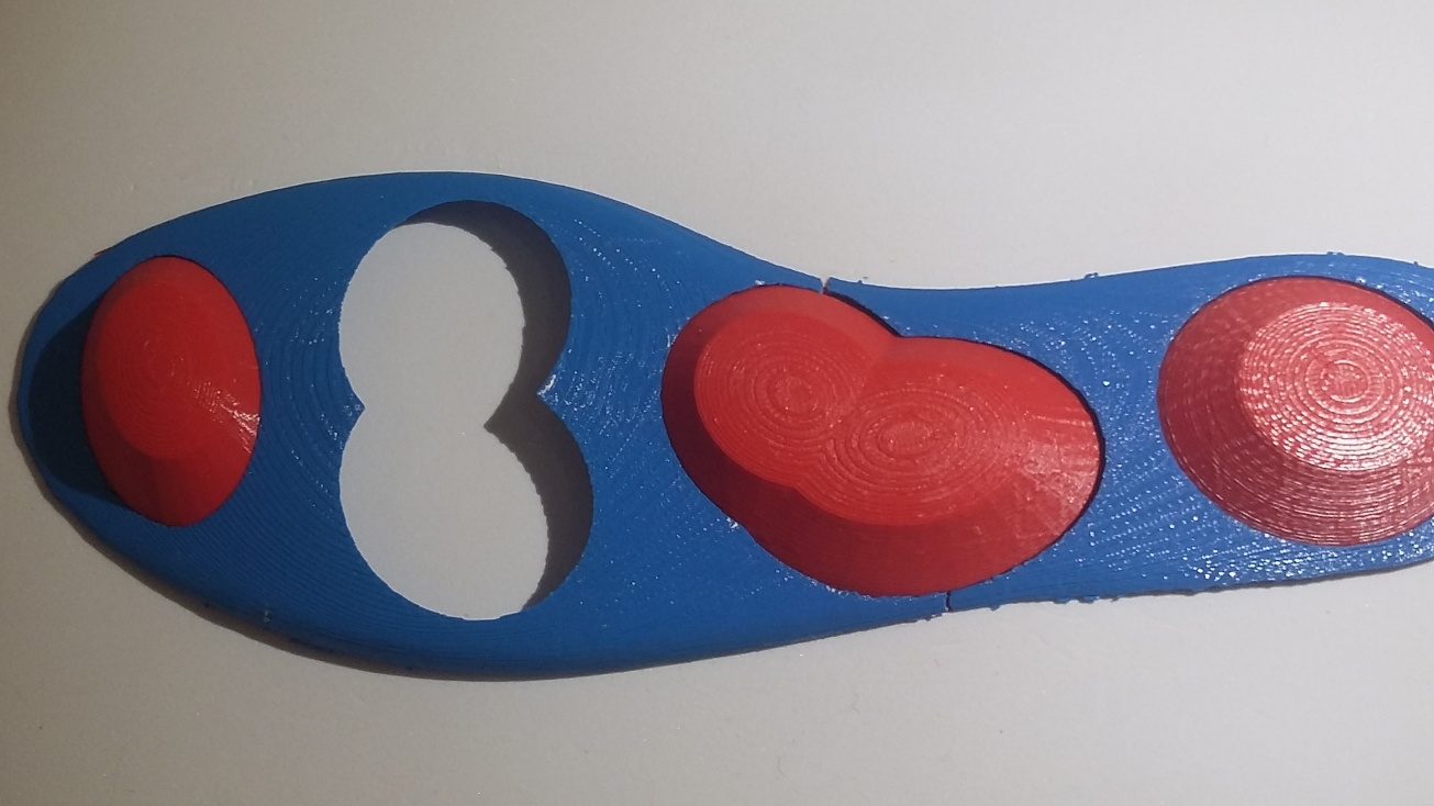
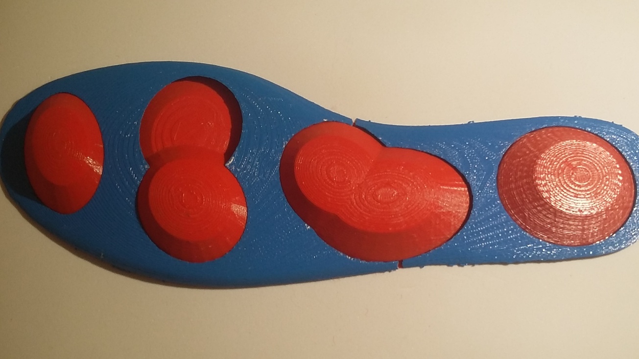
I am using 3D printed parts for the Outsole studs.
Project Planning
I planned to do some of the tasks for the final project during the other weeks, some of which I have mentioned in the previous weeks pages.
Scaning of the feet
Modeling of the insole, foot wear and the outer sole
Milling the insole for casting
3D printing of the designed footwear to use as mold for composite
Designing of pressure sensing circuit
Milling and making and programming the circuit
Making The insole sensors layer
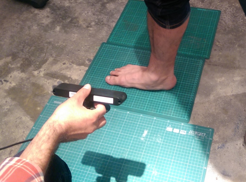
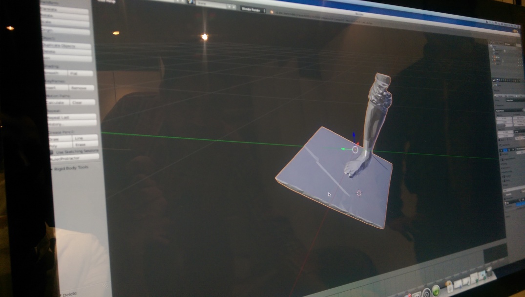
3D Scanning of feet
The foot scanning is the start point, from which I intend to capture much of the details necessary to customize the insole and the upper shoe.
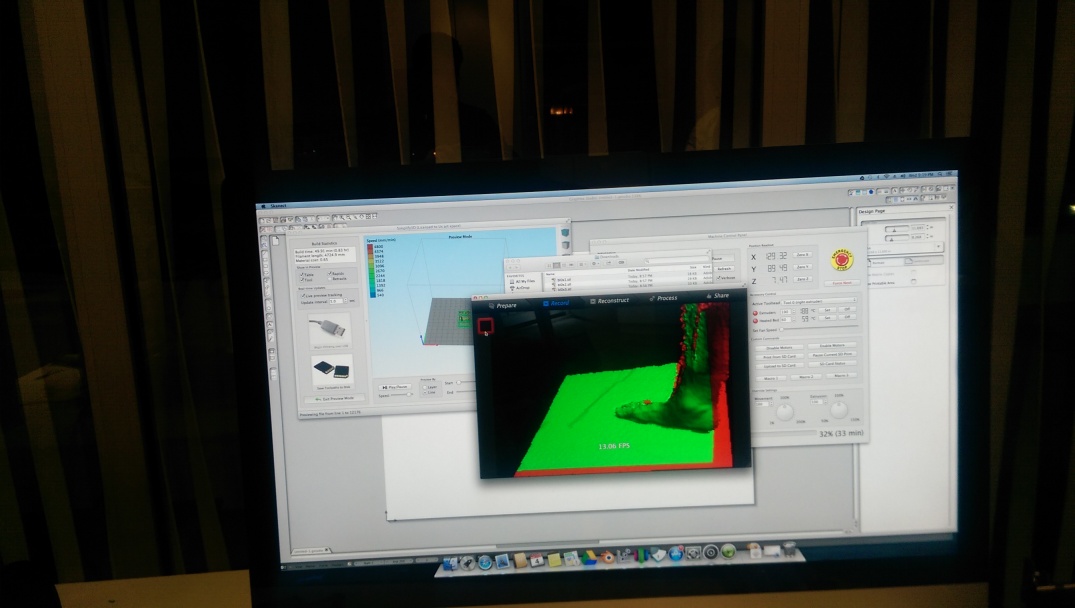
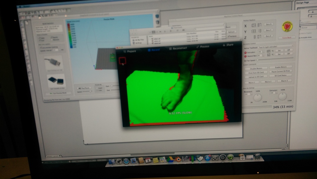
First I did the scanning while the feet was on grond, then when I realized that I didn't capture much of the sole details I decided to repeat the scanning while the foot is off the ground. I finally used the one where the foot is of the ground to create the impression of the foot sole.
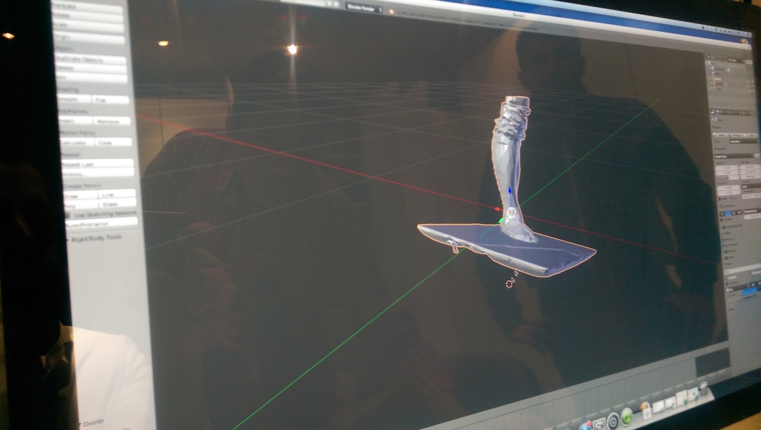

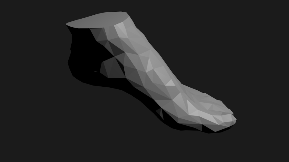
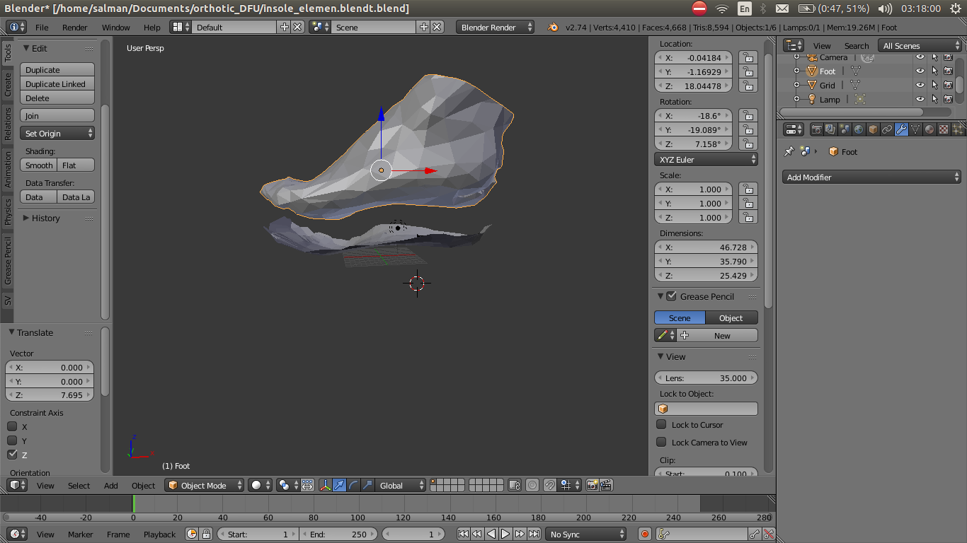
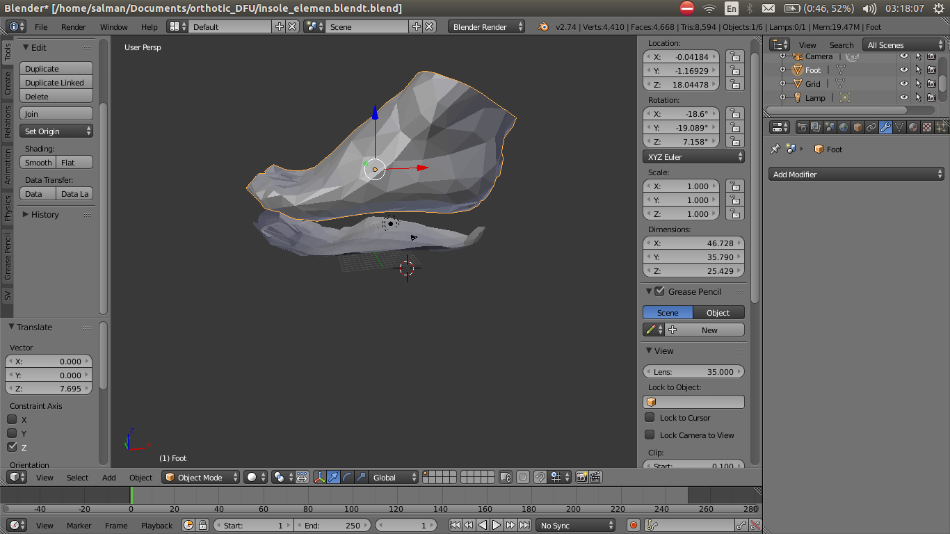
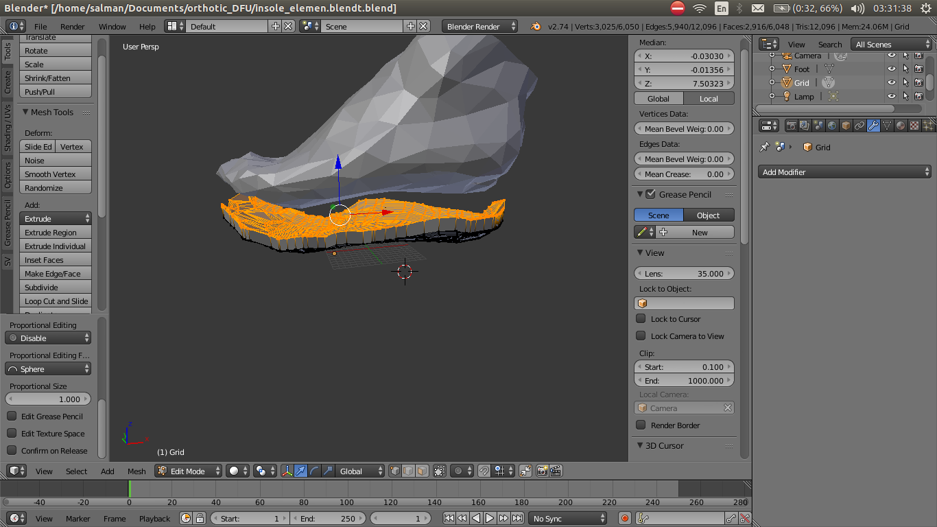
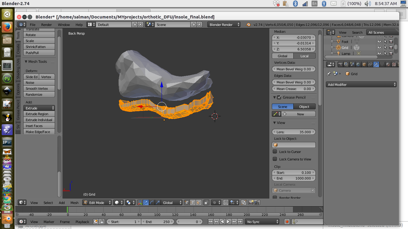
3D modeling software to creat identical foot impression
I did most of the modeling on Blender, I started with the surface mesh of the foot scan. I had to reduce the number of polygons because the file was to large and made the process of designing with it very difficult. So I ended up with a trade off between getting as much details or having a heavy file to handel.
3D Modeling of Foot wear and 3D printing as a Mold
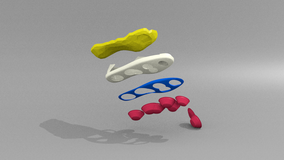
The final result is subosed to look similar to this design
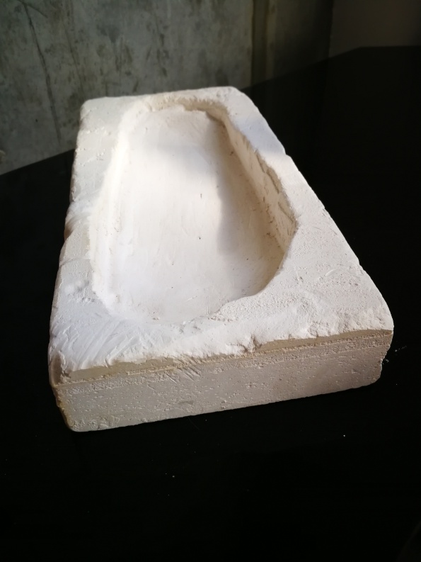
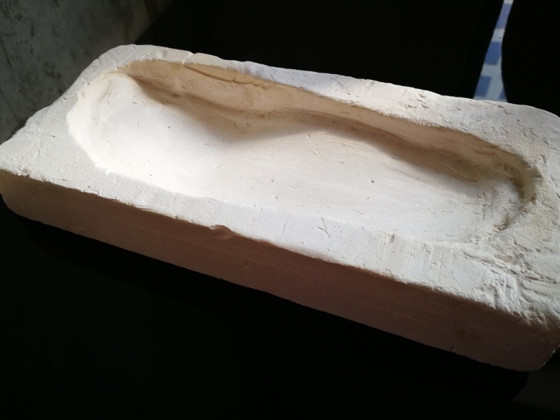
CNC Milling to create the custom In-sole and Upper layer
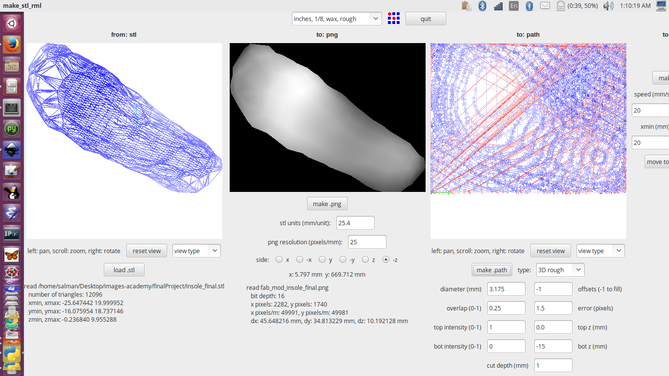
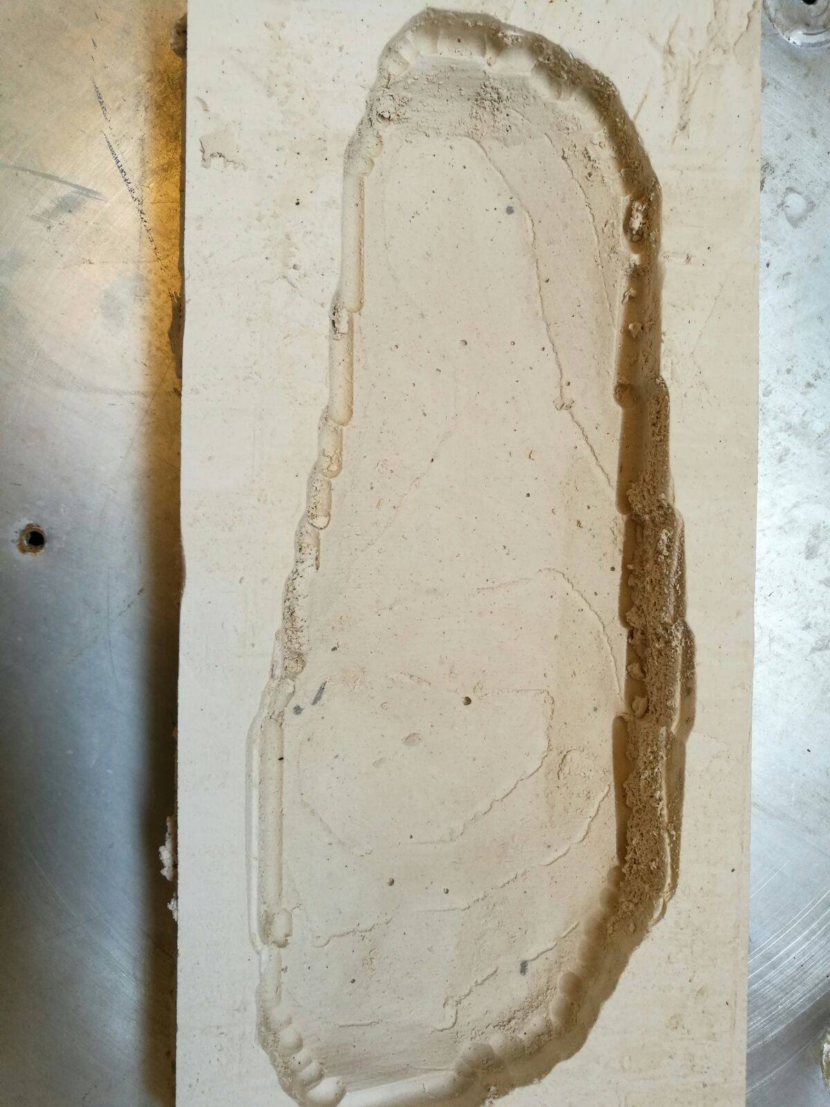
The gypsum mold was still wet when I was milling it, so when I tried to remove the depri from milling it got smugged.
I applied a spray mold release after a layer of sealant wax
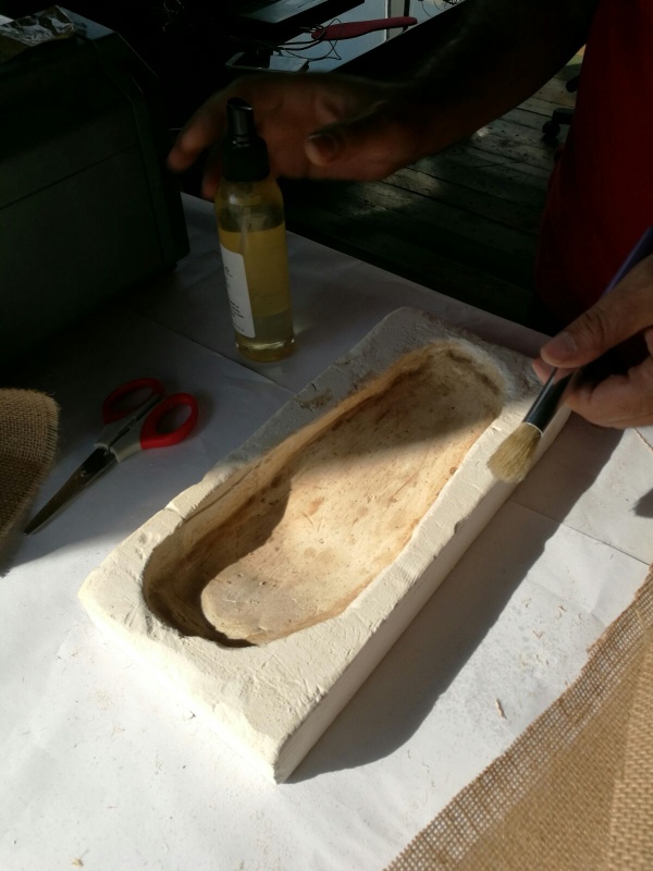
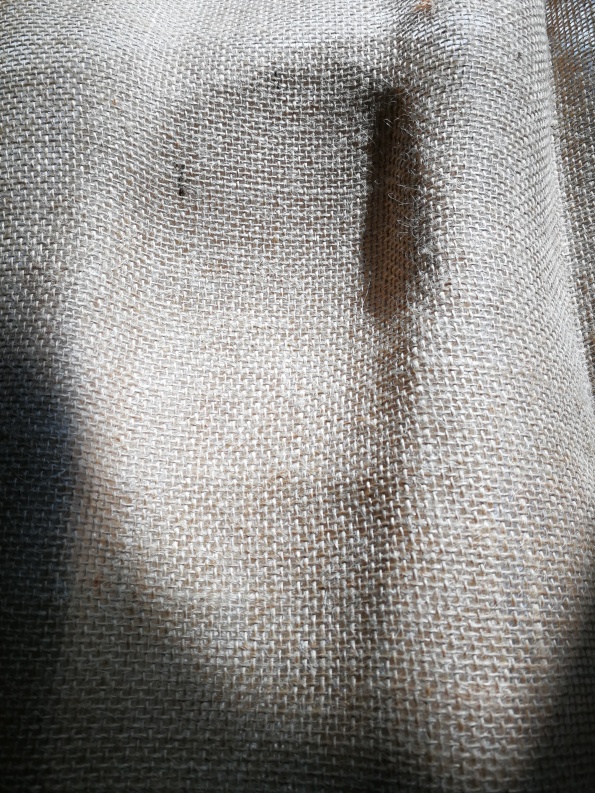
Thenstarted laminating with burlab
A parametric design tool to convert surface mesh dimensions to 2D cuts

Electronic Production for Mid-sole sensitive layer
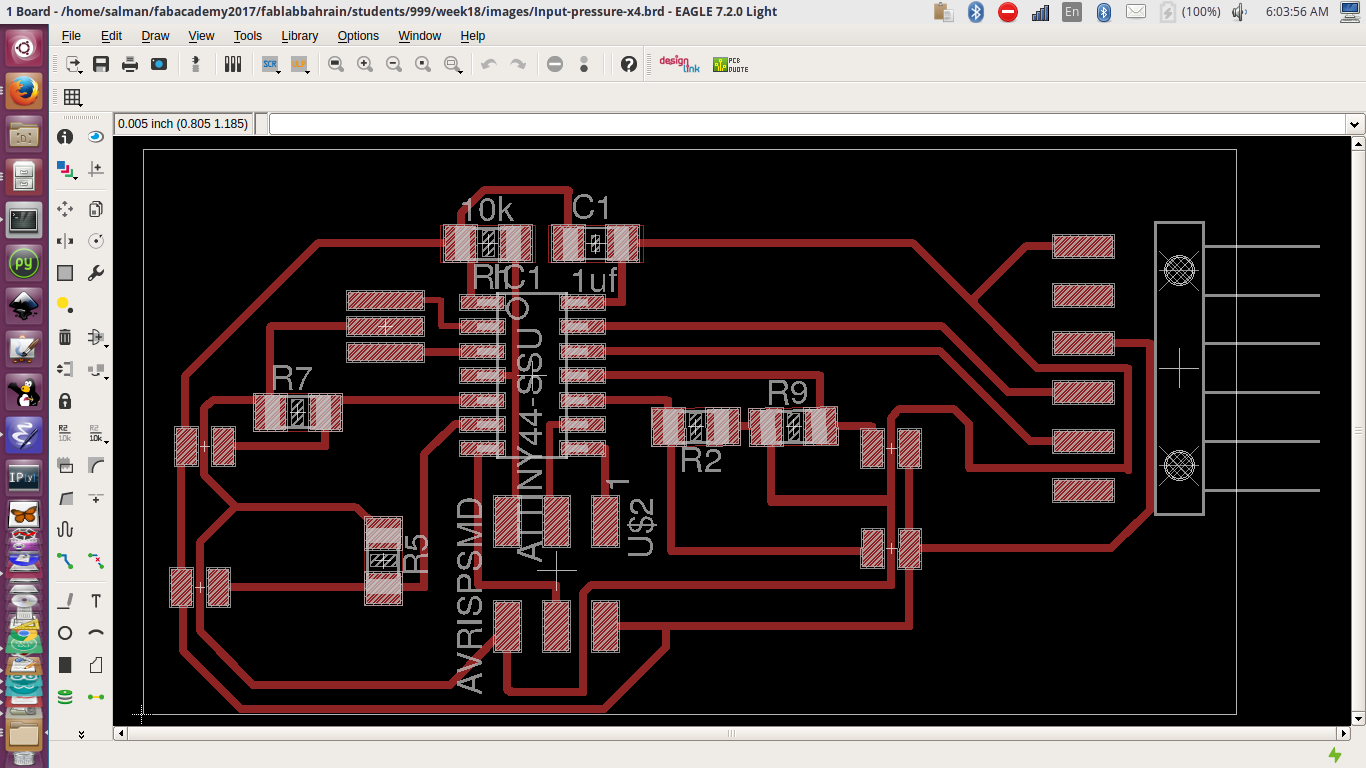
Eagle Presser sensing circuit-Board Eagle Presser sensing circuit-Schematic
I the pressure sensitive insole layer is made of two conductive fabric layers with velostat ( Piezoresistive material which has a resistance that decreases under pressure) in between.
 The test for two points pressure sensors, where visualized using two circles in processing. The size is influenced by the pressure and the sensor reading.
Then used three points with another visualization that maps the pressure points to the location on the insole.
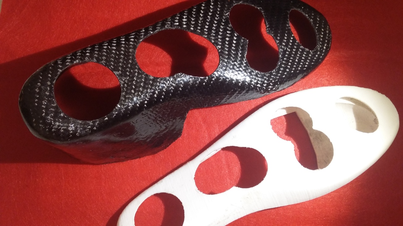
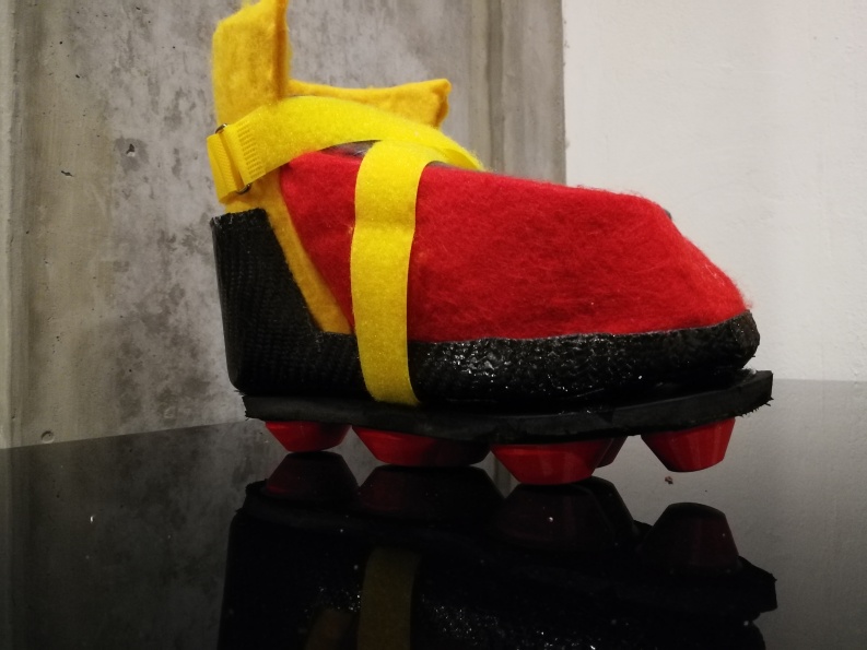
3D printing of Outer Sole offloading parts
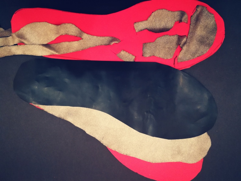
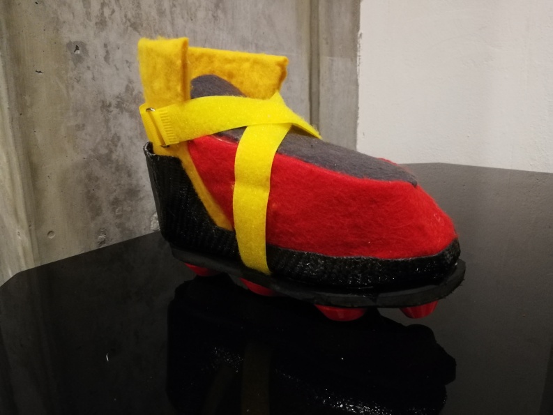
Designing and making the textile covers of the foot wear
I designed the textile pieces to be cut with laser, those pieces are supported with pieces of memory foam.
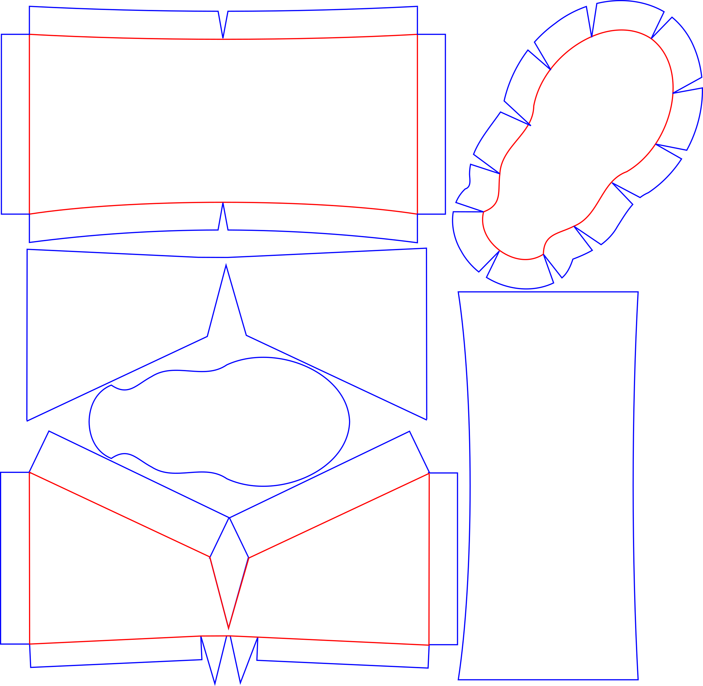
There is three parts that would cover the front side of the foot the top and around the ankle I chose three different color for each. They all attach to an insole piece.