WEEK TEN
-output devices-
ASSIGMENT: Add an output device to a microcontroller board you've designed and program it to do something.
Add an output device to a microcontroller board you've designed and program it to do something.
First of all I checked Emma's presentation in order to see the components I needed in my schematic but also other projects from preious years.
My goal was is to makea SOUND output device so first I open Eagle to start designing the schematic with the components.
To do so I type: add and Intro. Then the library of components is going to open and we must have selected the FAB library.
The components I picked TO GENERATE A SOUND OUTPUT are: resistor 10 k,two PINheader 2x2, ONE pinHEADER OF 2X3, avrISP smd, capacitor 1uF, ATtiny 45, N-MOS 1.1A.
So I connected everything in the way it should be and then I checked that everything was connected with the icon ERC.
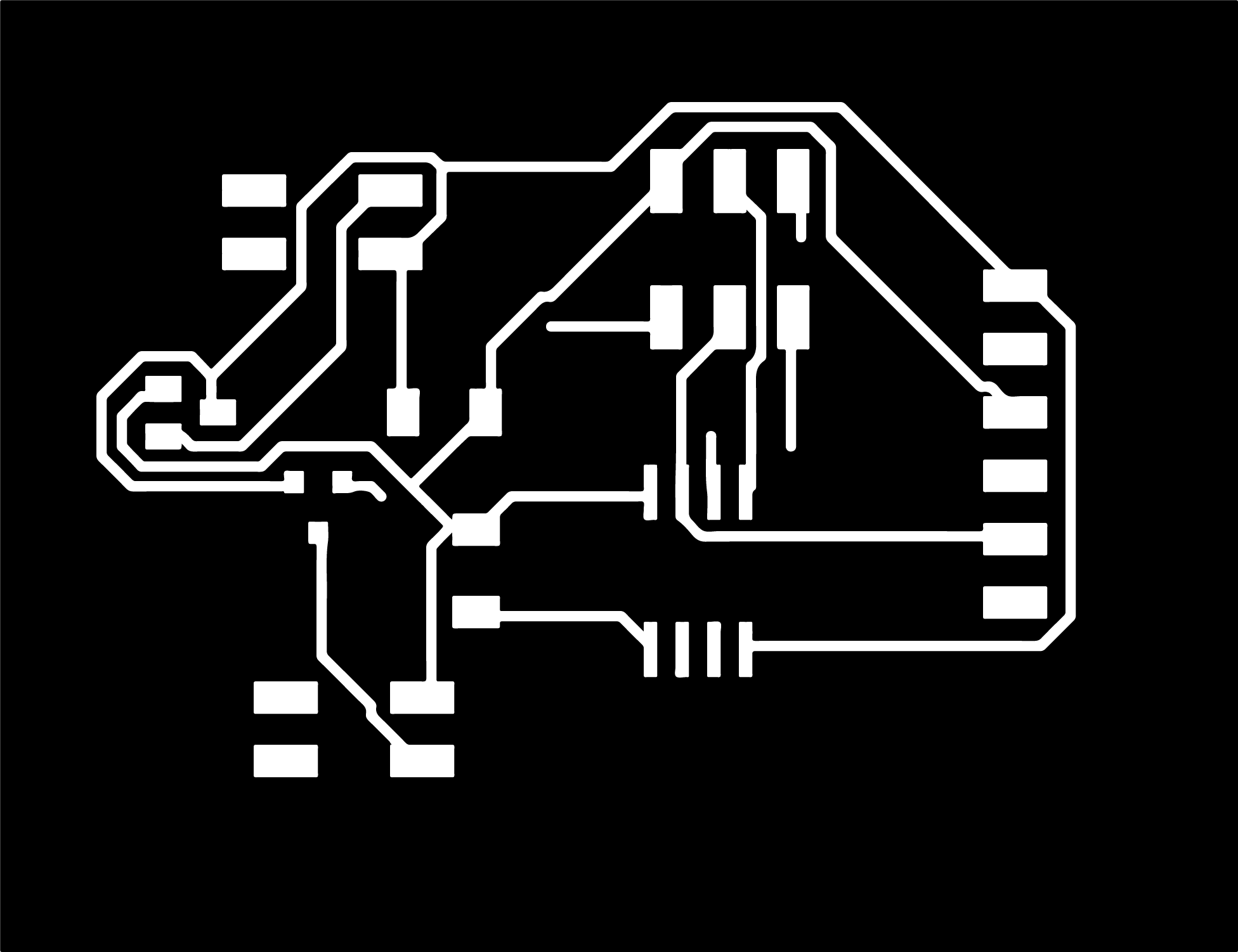
Next step is to go to board and make the traces with AUTOROUTER and select the one that has 100%. It is very important that all the traces are in the same layer:TOP layer. I had to repeat it again because firstly I didn't placed all the traces in the same layer so at the end there where traces missing after the milling.
Once the traces are done we have to create the two PNG monocrome files. One for the traces which we will use first and after it we will cut the outer line of our board.
As you can see there are blue traces which means I didn't put them all in the same layer so I had to repeat it again.
Once the PNG file is done we have to go to Illustrator and change the color in the outer line file. WE must have the square from insidee white and the rest all black. Once is done we save it again as a PNG.
We prepare the bed of the small milling machine and we calibrate the three axis. And then we prepare the file to mill our PCB board.
We take all the components from the electronics section and make sure that everything fits before soldering it.
The components I picked TO GENERATE A SOUND OUTPUT are: resistor 10 k,two PINheader 2x2, ONE pinHEADER OF 2X3, avrISP smd, capacitor 1uF, ATtiny 45, N-MOS 1.1A.
I checked that there where no shorts and that everything was connected correctly with the multimeter.
When I showed to Emma she told me that I don't need the FTDI pin header so I had to go to the schematic, delate it and mill again the board without it.
I check the orientation of the MISO in order to place the cable to the programmer and to do so I checked the schematic to see where is it in my board.
I connect the programmer with the board and I tryied to see if I see it in my computer. To do so I go to GITBASH and type:
But it says me error because I was using a ATtiny 45. sO I had to select instead of 44 a 45. And then it give me correct.
Next step was to prepare the cable to connect the speaker. To do so I failed the first try as I didn't check the orientation of the cables and I just place to random cables. So I secondly check the orientation and I placed I solder it with the speaker.
But when I pluged it in my computer it started to appering smoke so I inmediatly unreplug it. I spoke with Emma about it and she told me to remove the resistor and place a resistor in the red cable of the speaker. Th eproblem was that the maximum of volts I could use where 1V and I was usin 3V.
Finally I open Arduino software and I tryied to select the right clock and the right board and the burn the bootloader.
And finally and after a lot of trying I just programmed a code for sound.
Files: