Final Project
Final Project Development
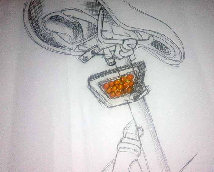
Finding the right form and shape wasn't as easy as it might sound.
I started by drawing by and what i thought I want my brake light to look like.
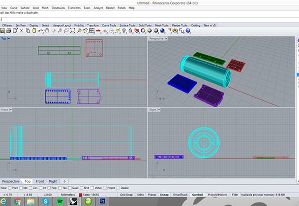
Then week two came and i used the assignment to make a 3d model of my light.
At this point i already had an idea of the electronic components tha I want to use on my
prototype so I started by designing the components
that i will use in the brake light to try to understand how can i fit them together.
And the bloks in order and design a possible box for the components, trying find the right shape and size.
But I was still not happy with my brake light case, and in the molding and casting and composites assignments
I thought i might make two alternatives for the cover for my brake light,
one in plastic and the other one with fiberglass and resin.
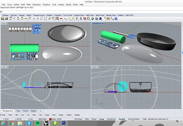
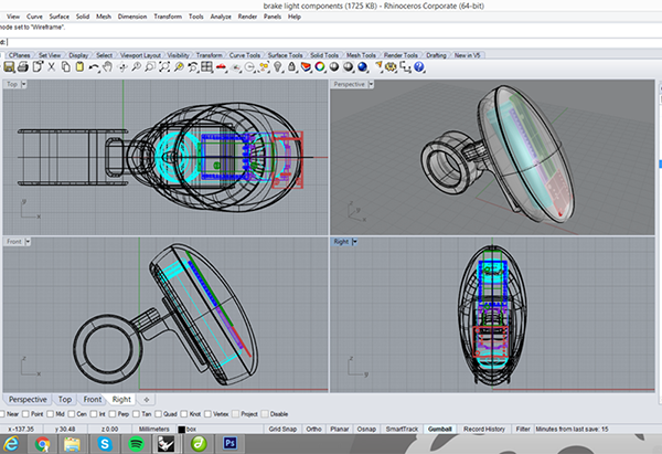
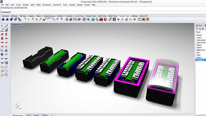
In order to make my molds I modeled another case alternative.
I used the same method, first i designed each component to the project and
then the enclosure,
the result was a diferent shape as you can see in the image bellow.
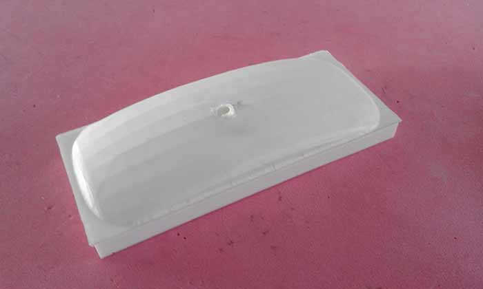
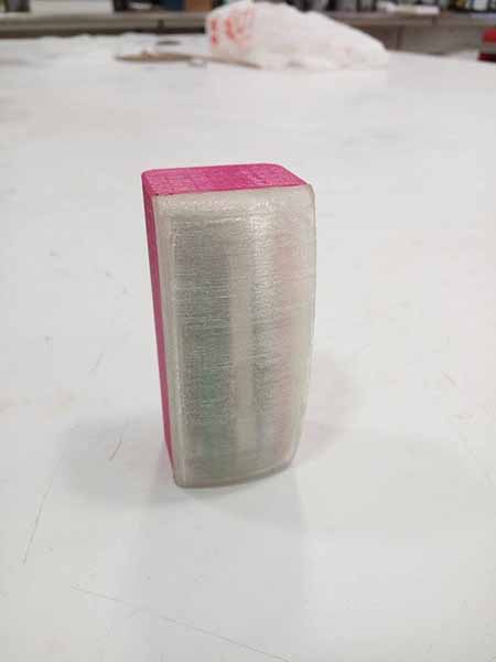
After designing the new cover for my brake light, i used week12 assignment to prototype it.
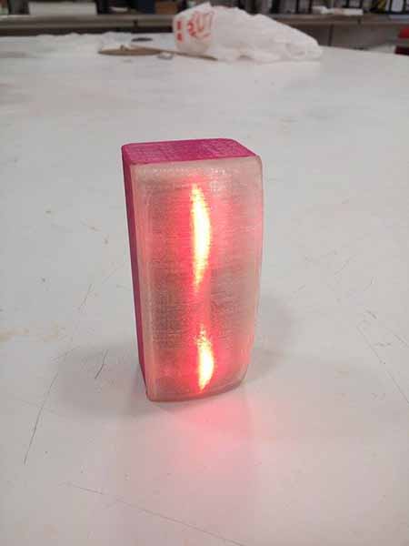
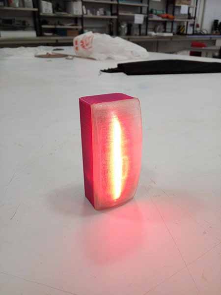
I did somenthing that I've never tryed before, carving a block of wax, molding and casting, the result was
pretty good as you can see in the image bellow, beside the little booble, and because initialy i
thought the cast would be tranparent =P
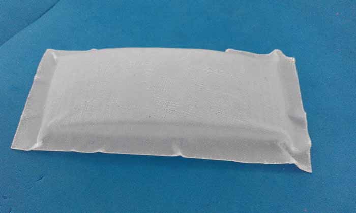
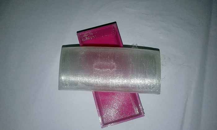
In week 14 i thought i might would make and alternative for my previous cover for my brake ligh, but this time
with resin and fiberglass. I started with a layer of release film and peel ply, next 2 layer of fiberglass and resin and another
ayer of release film and peel ply. After all the layers are piled, I used the vaccum bag with the vacuum pump.
And after 24 hours this was the final result:
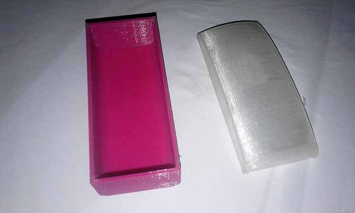
Still unhappy with the white and the bubble from the first try, and the hard time getting
rect angles from the fiberglass try, I ended up 3D printing it :P
Prototyping
So now we are very close to the final project presentation and all i have done so far is the idea
for the project and how the brake light should look like. The idea has changed a little bit from the first week.
I decided to start with the electronics because that is definitely the hardest part for me. So first and before designing the circuit board,
i connected the accelerometer and the leds to an arduino and programed them to work together.
This part happened in tree different moments:
1. Arduino and LED's
At first I thought that I would like to use NeoPixel because they allow numerous colors and by being controlled
individually by one pin allows also the creation of animations with the LEDs. But after I've implemented the code in arduino I
found that it was more difficult to control this kind of LED and since we managed to make our animation through other methods (by blinking)we chose to do this with the normal red LEDs.
2. Arduino and Accelerometer
The accelerometer that I used was the ADXL335. I choosed this one just because we already had one module of this
accelerometer here in the lab and because beeing an analog accelerometer the output is a continuous voltage that is
proportional to acceleration for each axis for the propouse of my final project it's the simpliest solution.
3. Power the Circuit
Lastly, was the time to find a way to power the circuit. To do that i used a 18650 rechargeable lithium battery from an
old laptop battery, so it's a protected-cell and a high density battery. To charge it I choose a BMS (battery management system),
the BMS manages a rechargeable battery by protecting the batery and preventing it from operating outside its safe operating area:
Over-current, Over-voltage, Under-voltage
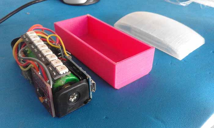
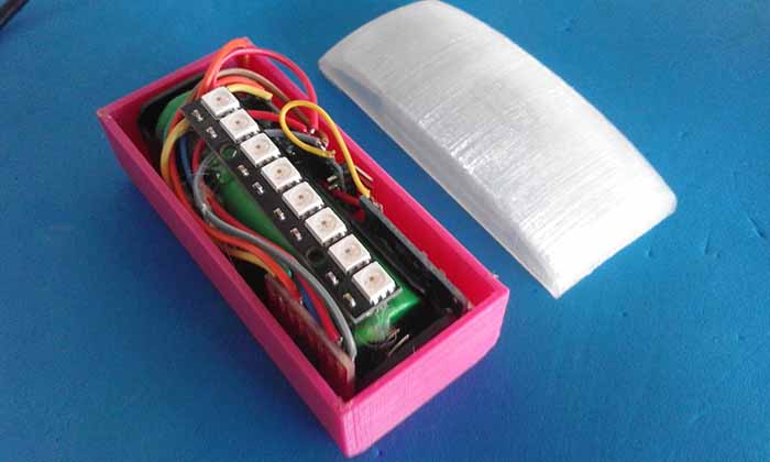
So first , I connected the accelerometer and the LEDs to an arduino and programed them to work together.
And tried to fit them into the enclosure:
Arduino prototype program:
#include <Adafruit_NeoPixel.h>
#define PIN 6
#define NUMLEDS 8
Adafruit_NeoPixel leds = Adafruit_NeoPixel(NUMLEDS, PIN, NEO_GRB + NEO_KHZ800);
int ACC_X_PIN = A0;
int ACC_Y_PIN = A1;
int ACC_Z_PIN = A2;
int X = 0;
int Y = 0;
int Z = 0;
int ledState = LOW;
unsigned long previousMillis = 0;
int f=0;
void setup(){
Serial.begin(9600);
leds.begin();
leds.setPixelColor(0, leds.Color(0, 0, 0));
leds.setPixelColor(1, leds.Color(0, 0, 0));
leds.setPixelColor(2, leds.Color(0, 0, 0));
leds.setPixelColor(3, leds.Color(0, 0, 0));
leds.setPixelColor(4, leds.Color(0, 0, 0));
leds.setPixelColor(5, leds.Color(0, 0, 0));
leds.setPixelColor(6, leds.Color(0, 0, 0));
leds.setPixelColor(7, leds.Color(0, 0, 0));
leds.show();
}
void loop(){
X=analogRead(ACC_X_PIN);
Serial.println(X);
if (X < 331 )
{
stopping();
}
else
{
cruising();
}
}
void stopping(){
leds.setPixelColor(0, leds.Color(255, 0, 0));
leds.setPixelColor(1, leds.Color(255, 0, 0));
leds.setPixelColor(2, leds.Color(255, 0, 0));
leds.setPixelColor(3, leds.Color(255, 0, 0));
leds.setPixelColor(4, leds.Color(255, 0, 0));
leds.setPixelColor(5, leds.Color(255, 0, 0));
leds.setPixelColor(6, leds.Color(255, 0, 0));
leds.setPixelColor(7, leds.Color(255, 0, 0));
leds.show();
}
void cruising(){
unsigned long currentMillis = millis();
if (currentMillis - previousMillis >= 500) {
previousMillis = currentMillis;
if (ledState == LOW) {
ledState = 255;
} else {
ledState = 0;
}
leds.setPixelColor(0, leds.Color(ledState, 0, 0));
leds.setPixelColor(1, leds.Color(0, 0, 0));
leds.setPixelColor(2, leds.Color(0, 0, 0));
leds.setPixelColor(3, leds.Color(0, 0, 0));
leds.setPixelColor(4, leds.Color(0, 0, 0));
leds.setPixelColor(5, leds.Color(0, 0, 0));
leds.setPixelColor(6, leds.Color(0, 0, 0));
leds.setPixelColor(7, leds.Color(ledState, 0, 0));
leds.show();
}
Testing:
After that it's time to check if it's all working.
As you can see the brake light has 3 states:
1.Off
2.Crussing
3. Braking
Fabrication
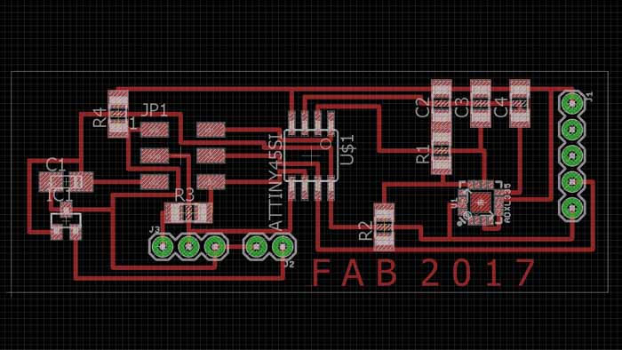
After the implementation of the individual modules with the arduino board I started the development of my own board.
Having in mind the KISS (Keep It Stupidly Simple) principle I designed a simple board with a minimum component count:
- For the power supply I used a 18650 lithium cell with a commercial BMS;
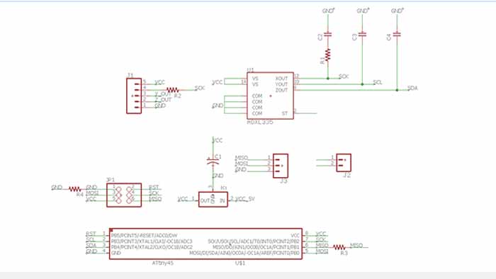
- For the accelerometer I used a ADXL335, which is analog and only require a 3.3 volts to operate and outputs a proportional voltage for each axis.
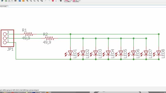
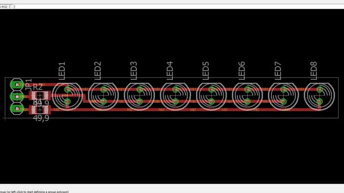
- To read and process the accelerometer information, the microcontroller that I used was the Attiny45 because have at least 1 ADC for reading the accelerometer and 2 PWM ports to control the led’s. Again, for the simplicity of the project, I use regular 5mm led’s for the output braking light.
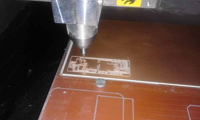
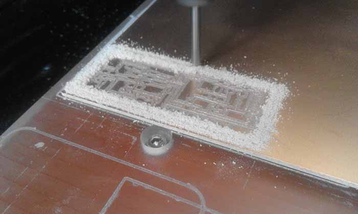
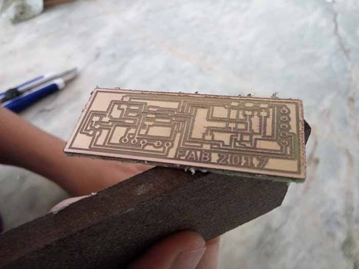
Milling the board:
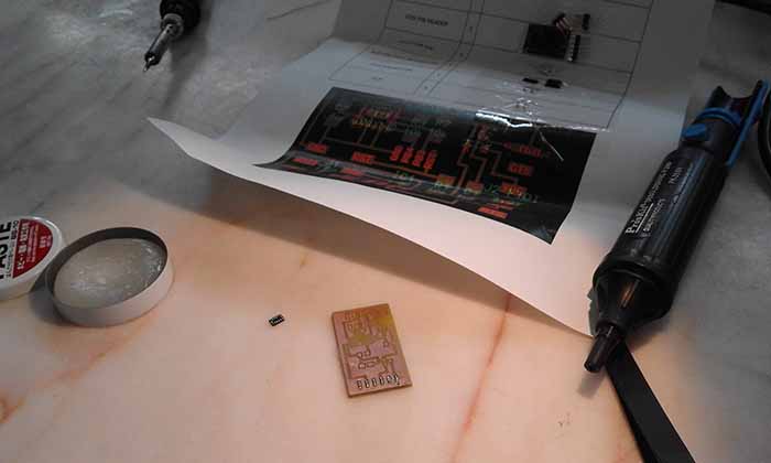
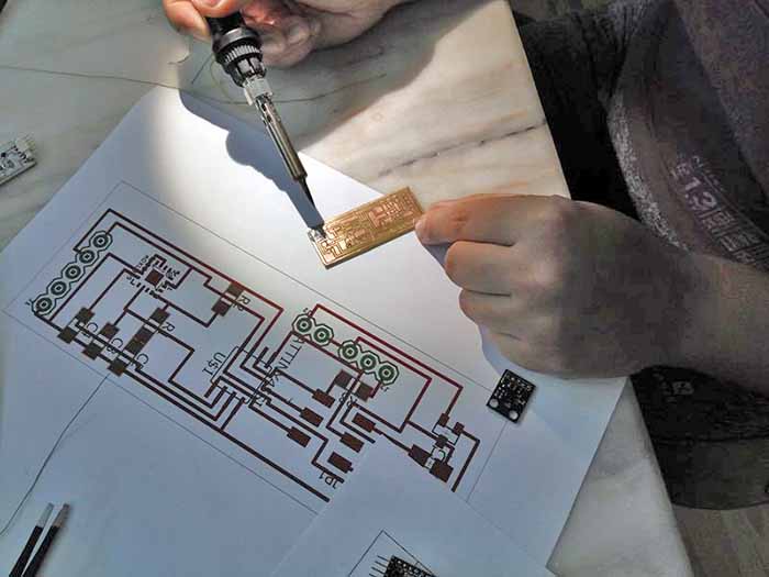
Stuffing:

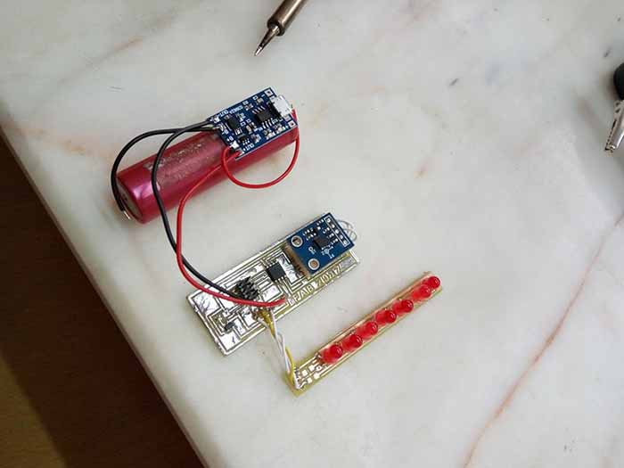
And this is my final result:)
You can download my files here.