3D Scanning and Printing
Week 5: Assignment
This week's assignment is defined in three folds:
- Test the design rules for our printer.
- Design and 3D print an object that could not be made subtractively.
- 3D scan an object and optionally print it (Extra credit for making your scanner).
Ultimaker 2
The 3D printer available in our FabLab is Ultimaker 2. It comes with a 47 pages user manual, which is sufficient to understand it's installation and working. For further assistance and better understanding one can visit following link.
https://ultimaker.com/en

Specifications of the machine
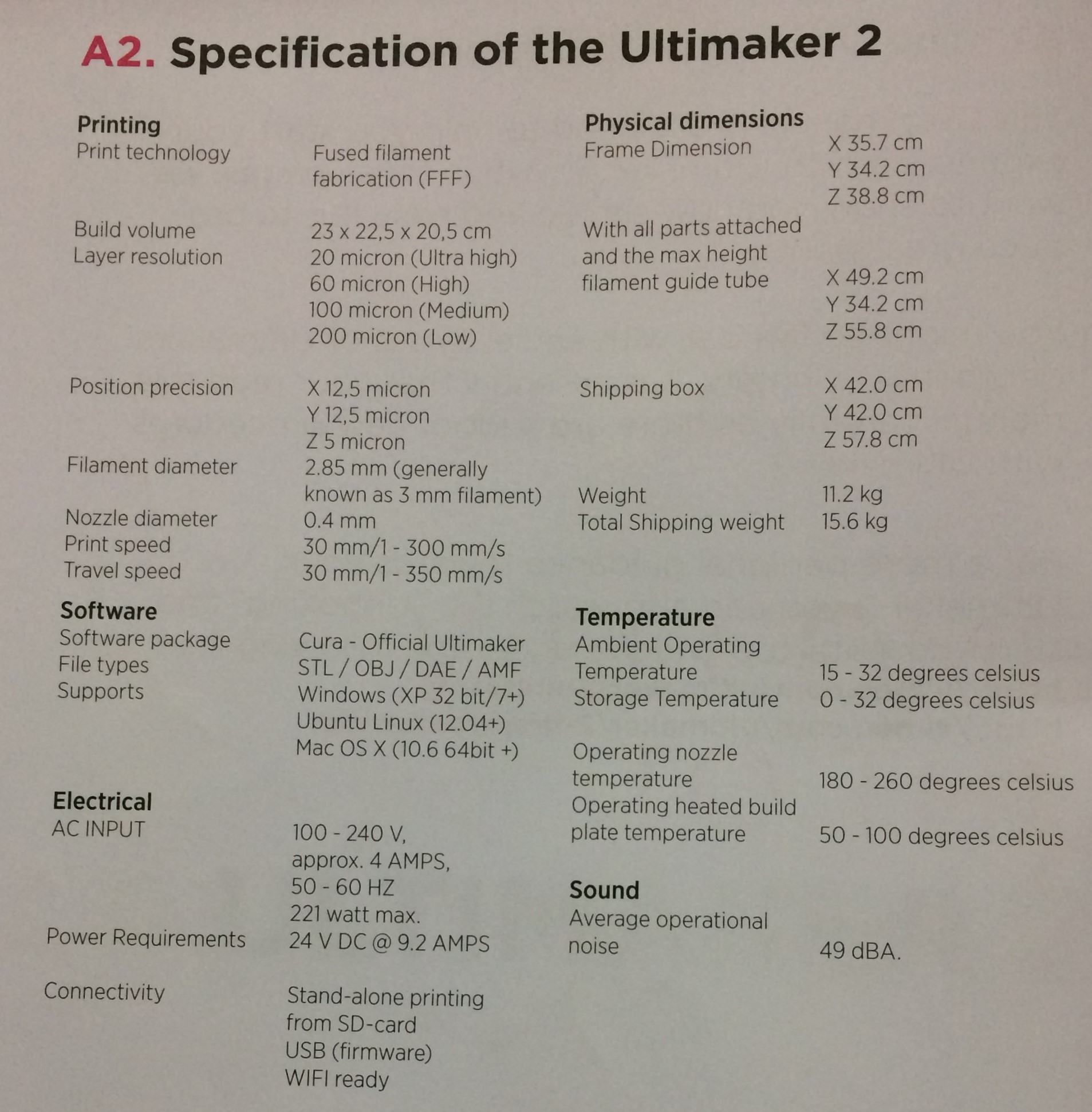
Testing design rules of our printer
To test the resolution and building capacity of integrated shapes and contours of our printer, we downloaded one image from Thingiverse as shown below and printed it on ultimaker.
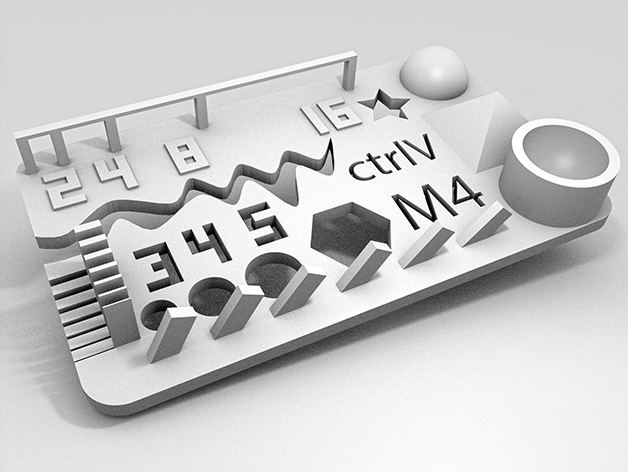
The test sample has following parameters:
- Size: The object is 2x50x30mm (baseplate)
- Hole Size: 3 holes (3/4/5mm)
- Nut Size: M4 Nut should fit perfectly
- Fine Details: pyramide, cone, all numbers
- Rounded Print: wave, half sphere
- Minimum Distance & Walls: 0.1/0.2/0.3/0.4/0.5/0.6/0.7mm
- Overhang: 25°/30°/35°/40°/45°
- Bridge Print: 2/4/8/16/mm
- Surface: All the flat parts
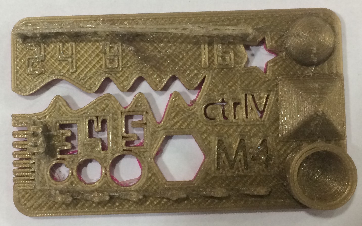
After comparing both the above images, following conclusions can be made:
- The minimum wall thickness that was printed was 0.5 mm.
- It can print 25 degrees without supportive material.
- Does not require support material or a raft when the print begins.
- Support material is required for making a overhanging of more than 5mm.
- Support material is hard to break off and does not do a great job with assemblies of internal parts.
- The wall thickness of .5 mm measures an actual measurement of 0.48 mm to 0.49 mm.
- Build size is limited to 223 x 223 x 205 mm.
- It can print in PLA or ABS material.
- The resolutions can be made better my reducing the printing speed.
Designing and Printing a part from ultimaker
Steps
- Making a 3D Model on Solid works
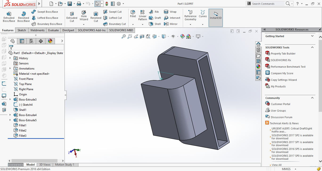
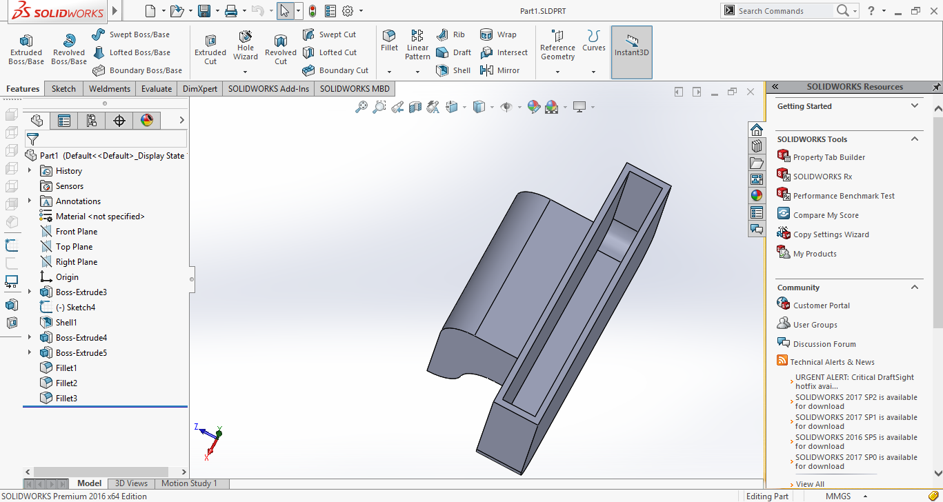
- Saving the Solidworks file as .stl
- Importing .stl to Cura software.
Cura software is open source, which creates a seamless integration between hardware, software and materials for the best 3D printing experience around. It is having many options with which, one can play to manipulate his design resolutions and parameters.
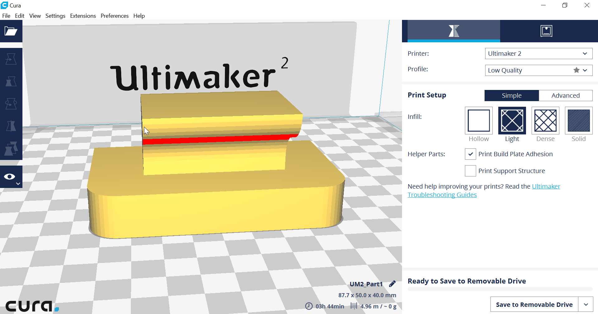
On right hand side bottom corner one option is available (save to removable drive), by clicking on this .gcode image is created which is fed to the ulimaker and printing of the part can be initiated.
Actual Printed Component
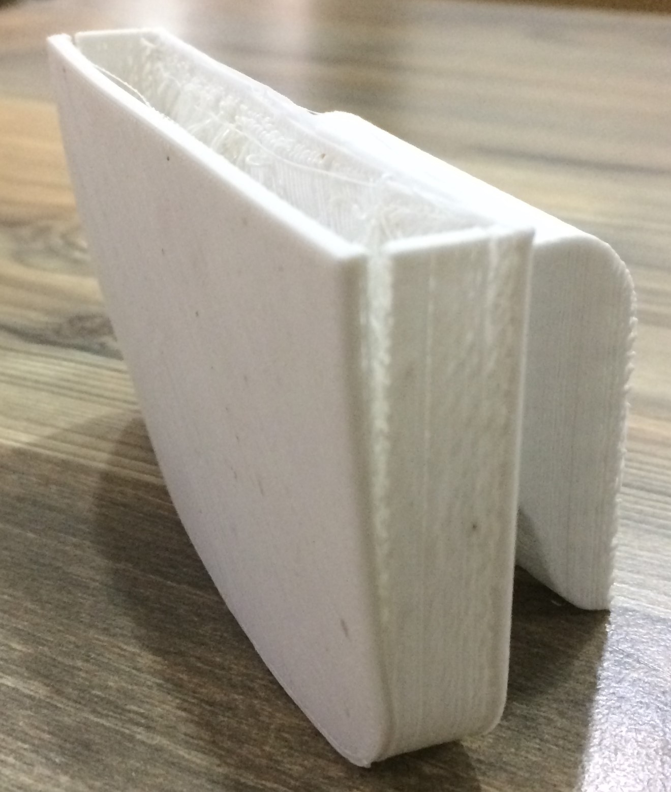
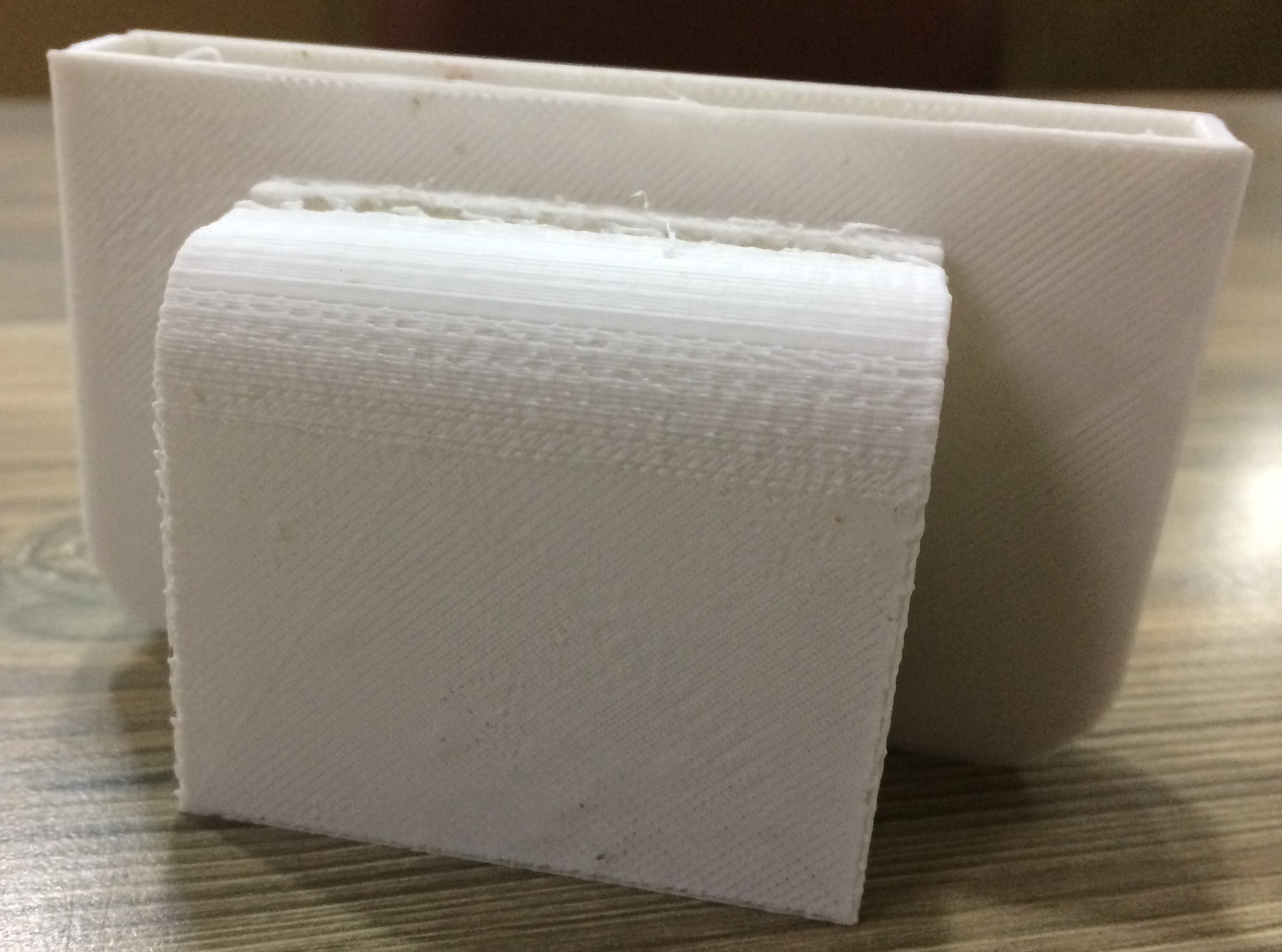
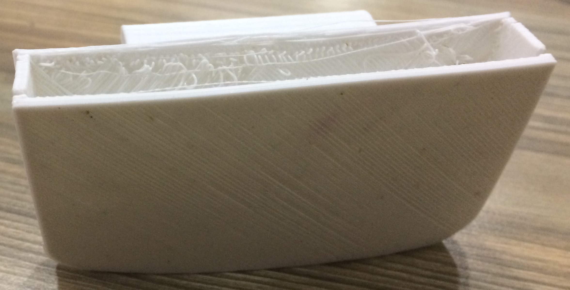
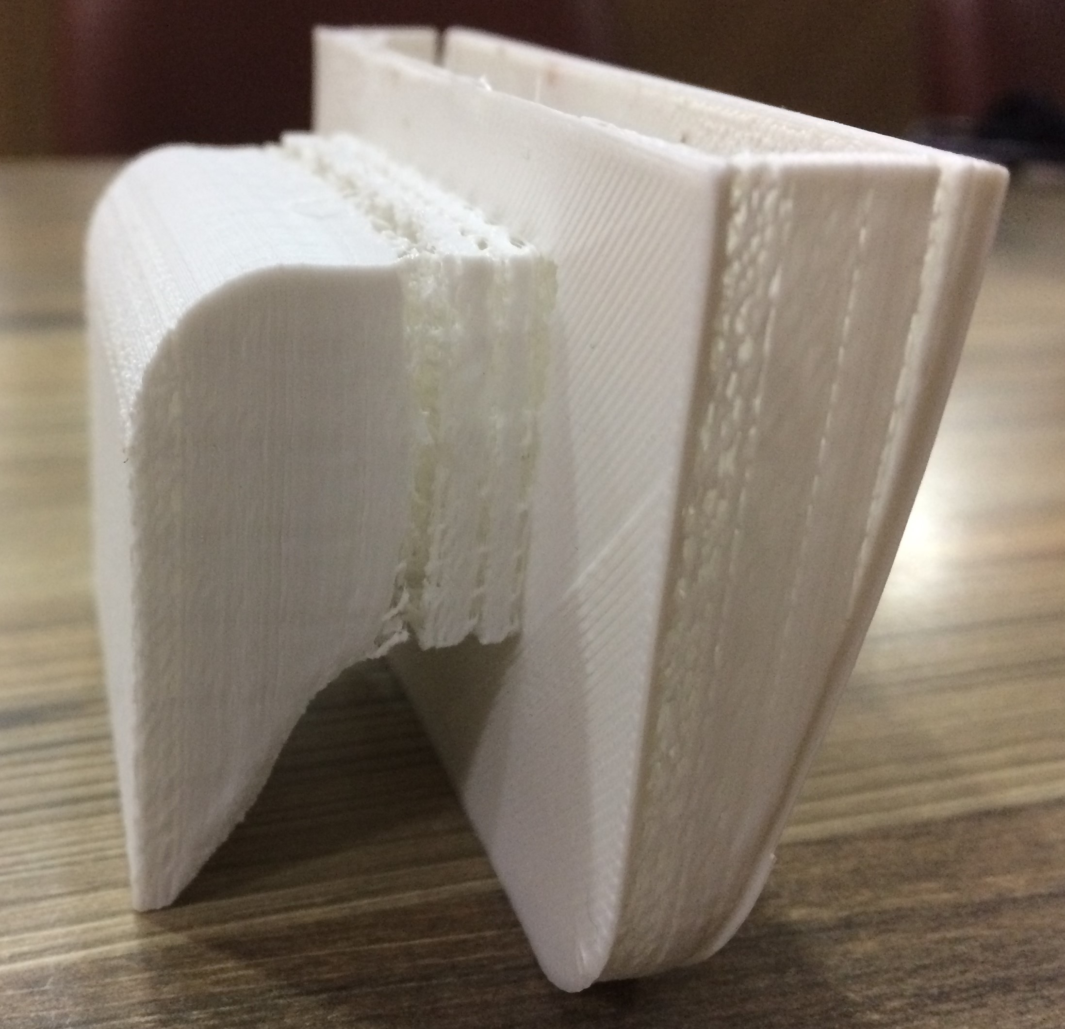
Defects in the 3D printed parts and their remedies.
- The printing surface was not cleaned properly before the print. So, the material didn't stick well on the printing surface because of which in between the layer came off and the regularity of the surface was disturbed. This problem can be resolved by applying mild adhesive to the printing surface after cleaning it properly.
- The orientation of the workpiece in the cura software was not set properly, as seen above. Therefore, while printing the top layer their was no support material and because of which Irregularities can be observed between the two walls. This error can be resolved either by providing the right orientation (i.e. rotating it by 90 Degress in this case) or by providing support material.
- Walls of the component shear off because walls thickness was less and forcefully i tried to push my fingers inside.
Subtractive Manufacturing
Cutting down to size: Traditional manufacturing processes, also known as 'subtractive' processes, remove material from a workpiece to create the desired geometry; examples of these processes include milling, turning, or sawing. Subtractive manufacturing begins with a solid block of material that is modified by a series of processes such as cutting, drilling, and milling to remove material. One such example is using an advanced CNC machine, where the machinist is able to rotate the block around multiple axes (x, y and z) to make the necessary cuts, channels, and holes, and any other features that can be produced by material removal. Afterwards products often need to go through several steps of machining and assembly before they are finalized.
With subtractive manufacturing, there are a variety of options in terms of materials and processing methods. Softer materials may be easy to machine to their final shape, but will wear more quickly. Harder materials may be more difficult to work with and achieve complex geometries, Extensive attention to processing parameters such as tool wear might also be required.
It is not advisable to make this part using subtractive manufacturing because of the following reasons.
- Material wastage will be very high. If a block of 70x30 mm is taken for millling then, 70 % of material will be wasted in form of chips and only 30 % is used to get the milled part.
- Depth of the groove is very high, so special fixtures and tools will be required to mill the portion.
3D Scanning
In the following three ways i did 3D scanning:
- Using Carl Zeiss's Contura G2 Vast XT GOLD CMM
- Using XBOX360: Kinect Sensor
- Using VisualSFM and MeshLab
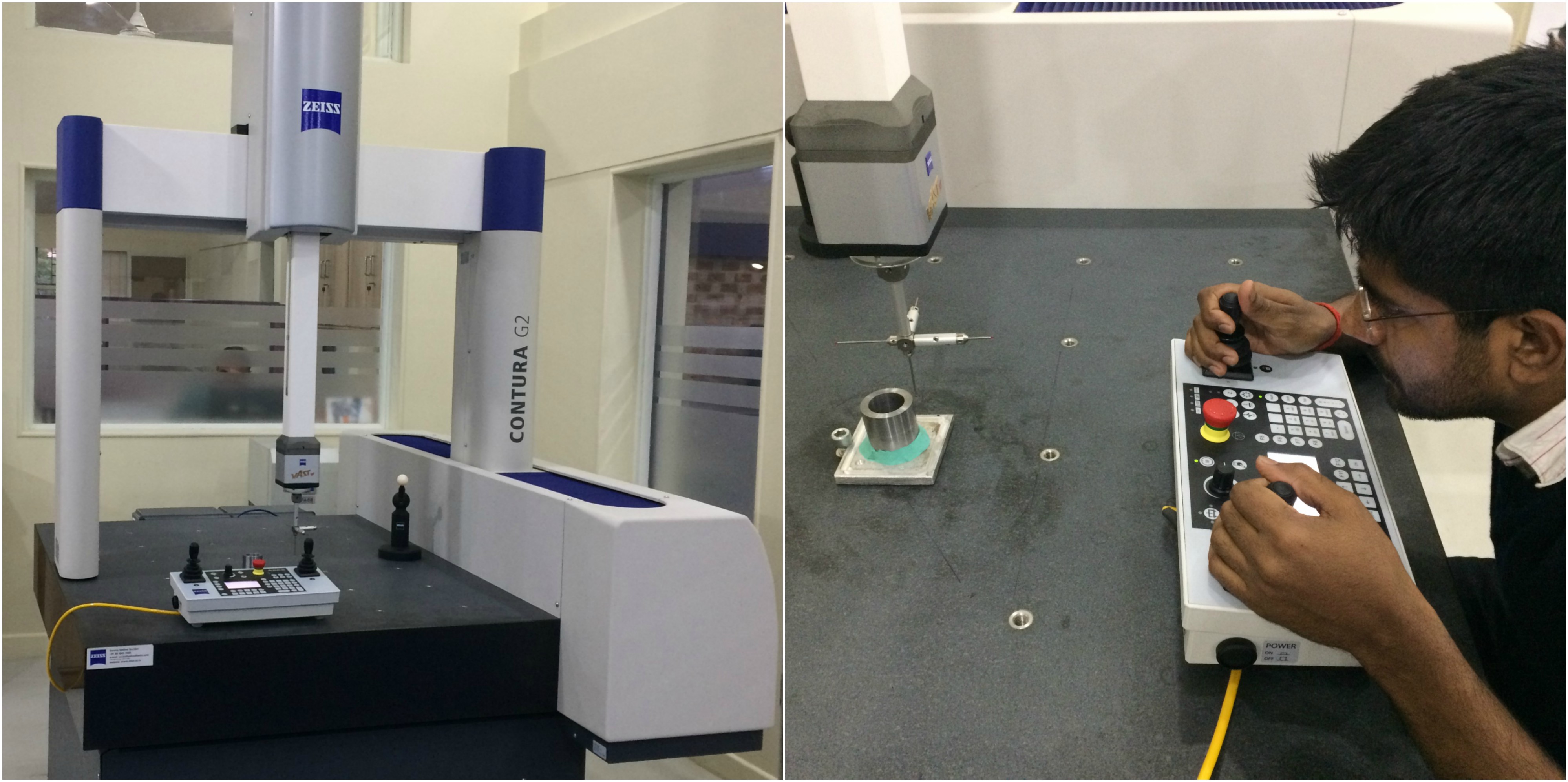
Carl Zeiss's Contura G2 Vast XT GOLD CMM
We have Contura G2 in our lab, which is basically used for inspection to assure quality check in most of the industries. The affordable CONTURA G2 is ideal for small and mid-sized companies wanting the benefits of high-speed scanning. VAST scanning technology enables form inspections at maximum speed with high-quality measuring results. Process changes are detected at an early stage, high production quality is ensured and rejected parts are reduced. It's bed size is 700x1000x600 mm with accuracy of 1.58 macrons/350 mm length. Following link can be visited to know more about the machine.
www.zeiss.co.in
Contura G2 Manual
Steps to do scanning with Carl Zeiss's Contura G2 Vast XT GOLD CMM
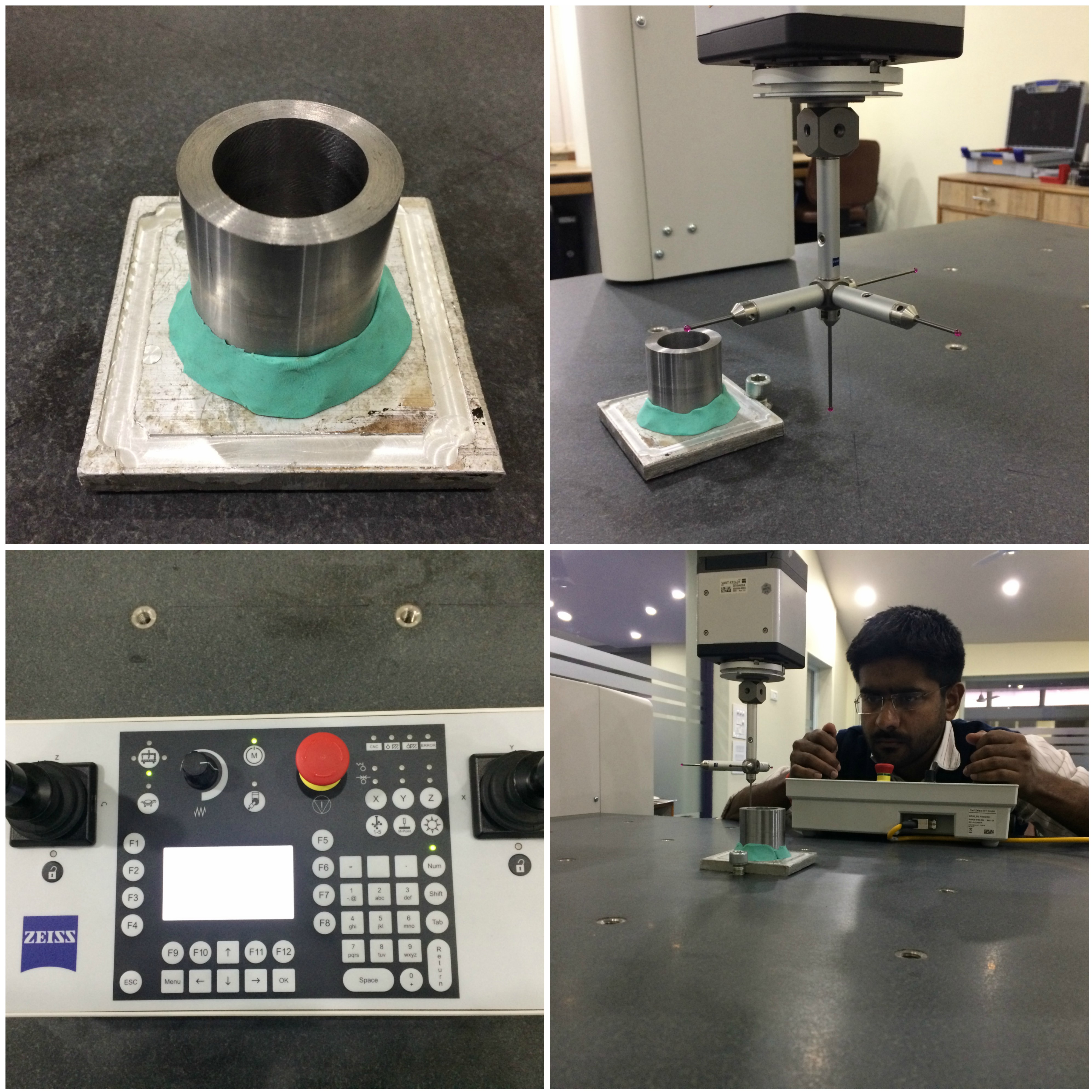
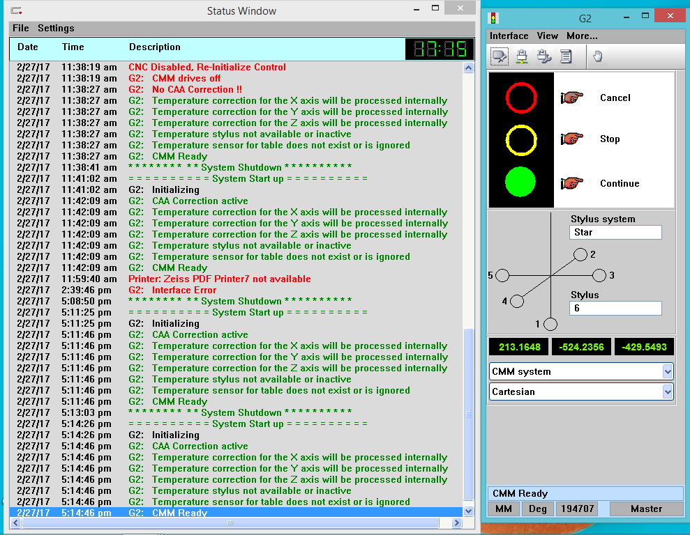
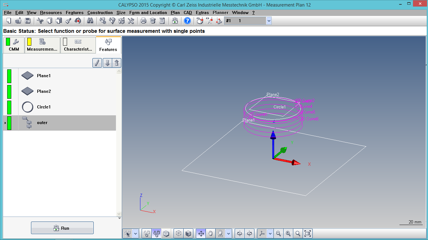
- Turn on the machine and connect it with a system. Install Calypso in the system (It's not open source), I used Calypso 2015 version. After opening Calypso u will get two windows as shown below, which will be running in the background. One is status window, which will continuously tell about all the processes happening within the machine and other window is used to turn on or off the machine/processes.
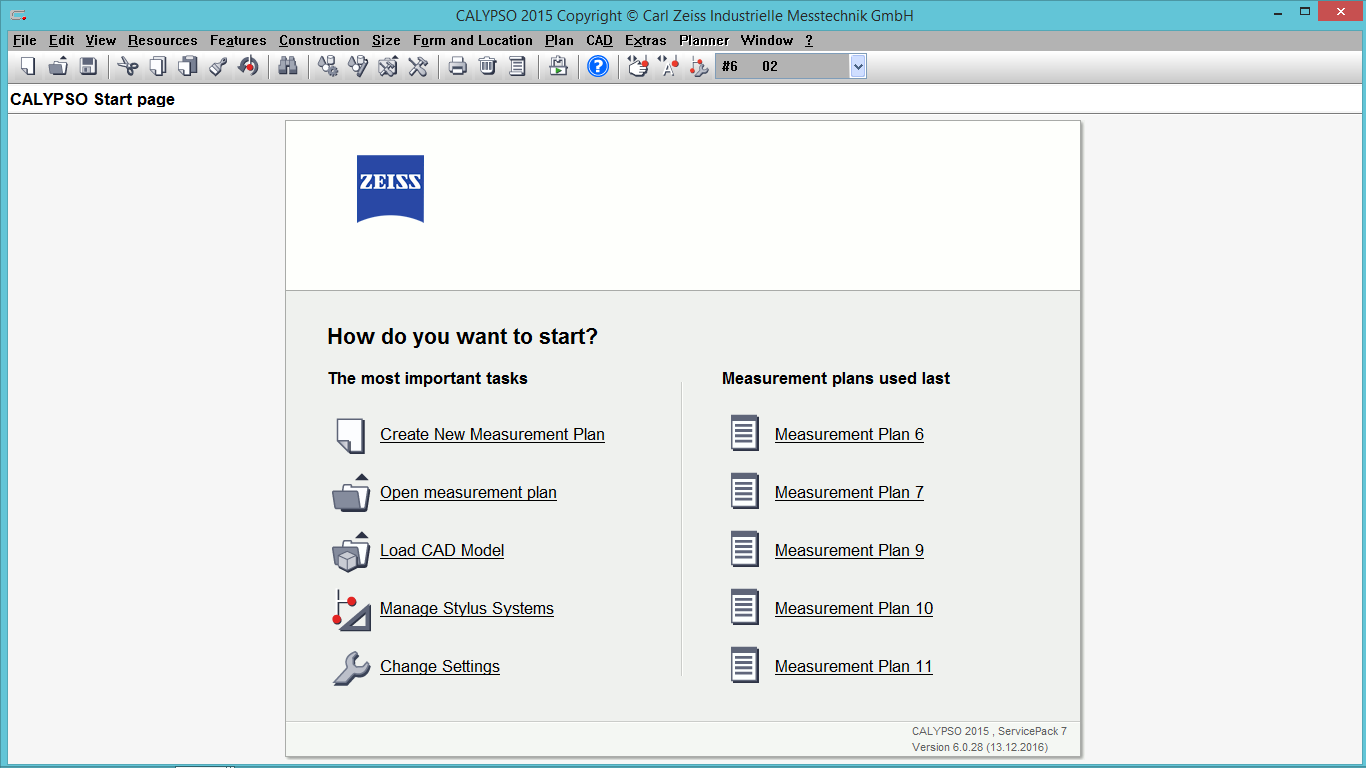
- After opening Calypso following window will open up and create new measurement plan need to be clicked upon.
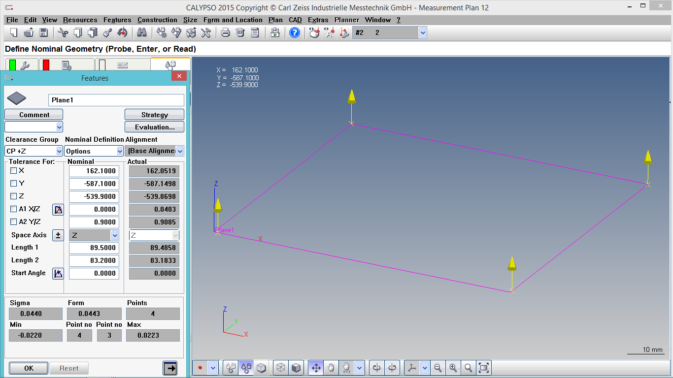
- Define datum and with the help of control panel,touch your proble at four different places. All this steps will be shown in status window and as u touch all the points one plane will be created on the destok, as shown below.
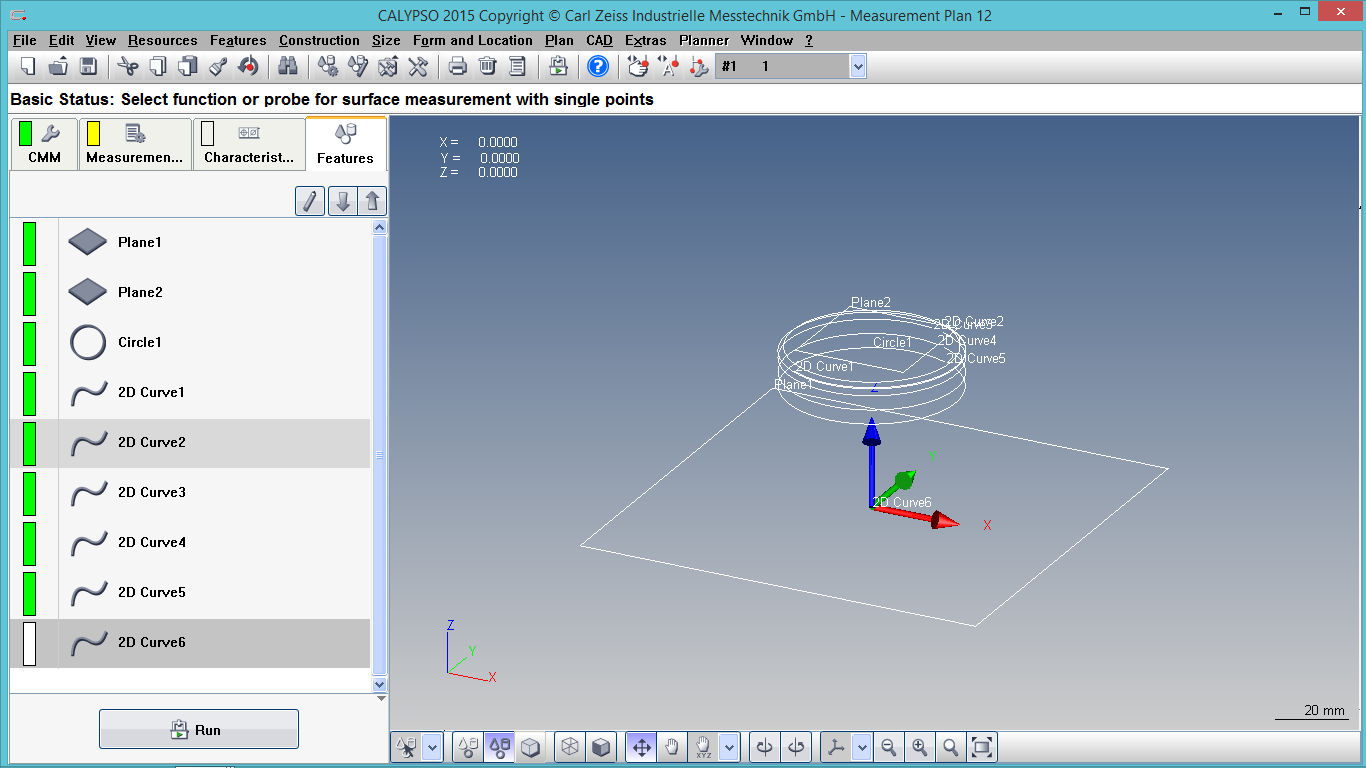
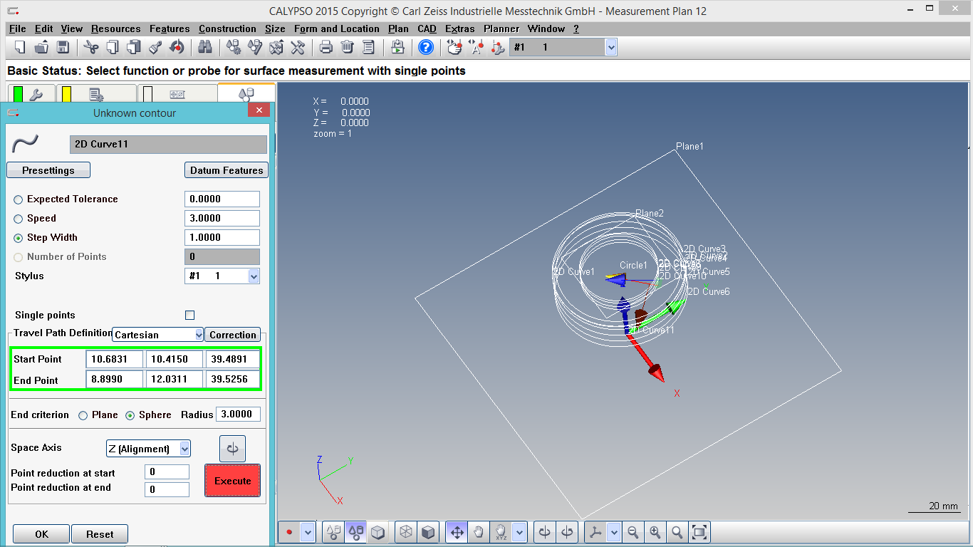
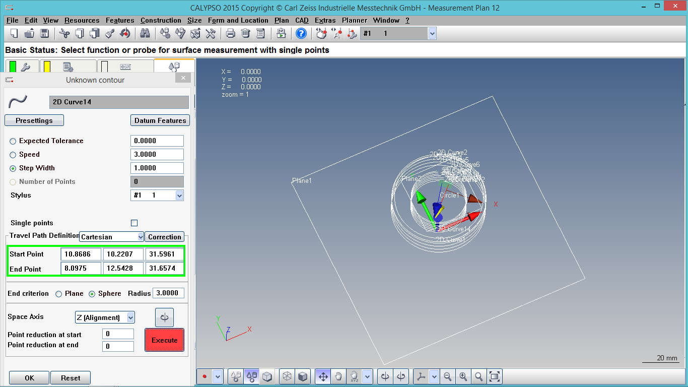
- Similarly, keep rotating the probe over the surface and it will generate point cloud data.
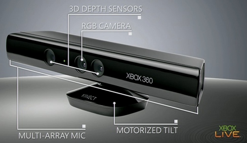
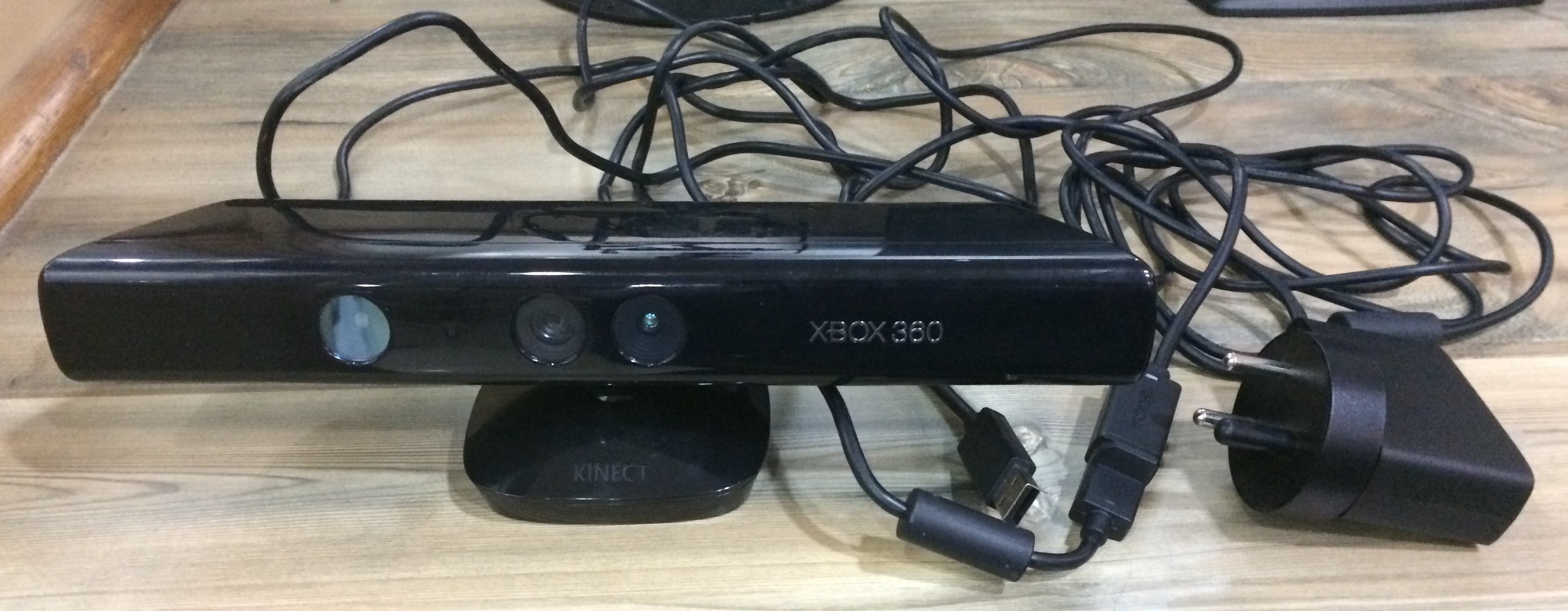
XBOX360: Kinect Sensor
Kinect (codenamed Project Natal during development) is a line of motion sensing input devices by Microsoft for Xbox 360 and Xbox One video game consoles and Windows PCs. Based around a webcam-style add-on peripheral, it enables users to control and interact with their console/computer without the need for a game controller, through a natural user interface using gestures and spoken commands. Using this kinect sensor i scanned myself.
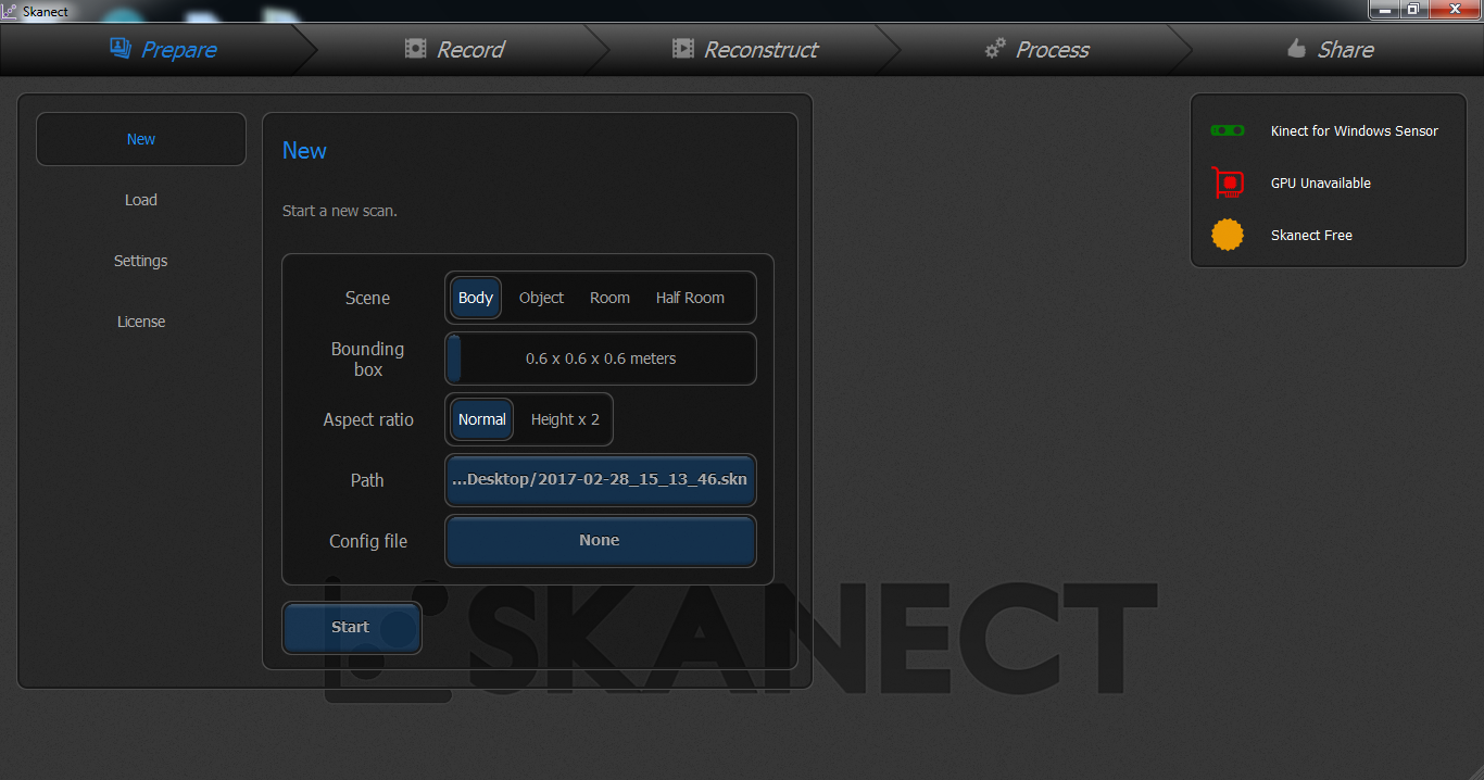
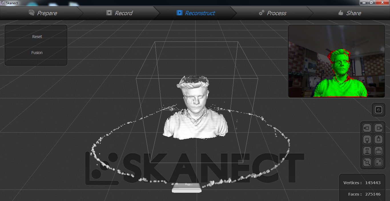
Steps to do scanning with XBOX360: Kinect Sensor
Connect your kinect sensor with system and give power suppy to it. Afterwards I downloaded Skanect and started scanning after setting all the parameters. Make sure all the supporting softwares are also installed for intrupted working of kinect.
VisualSFM and MeshLab
VisualSFM is a GUI application for 3D reconstruction using structure from motion (SFM). VisualSFM runs fast by exploiting multicore parallelism for feature detection, feature matching, and bundle adjustment.
For more information on VisualSFM, Click here
MeshLab is the open source system for processing and editing 3D triangular meshes. It provides a set of tools for editing, cleaning, healing, inspecting, rendering, texturing and converting meshes. It offers features for processing raw data produced by 3D digitization tools/devices and for preparing models for 3D printing. It can be downloaded from following link:
www.meshlab.net
Steps to do scanning with VisualSFM and MeshLab
- Download VisualSFM and MeshLab.
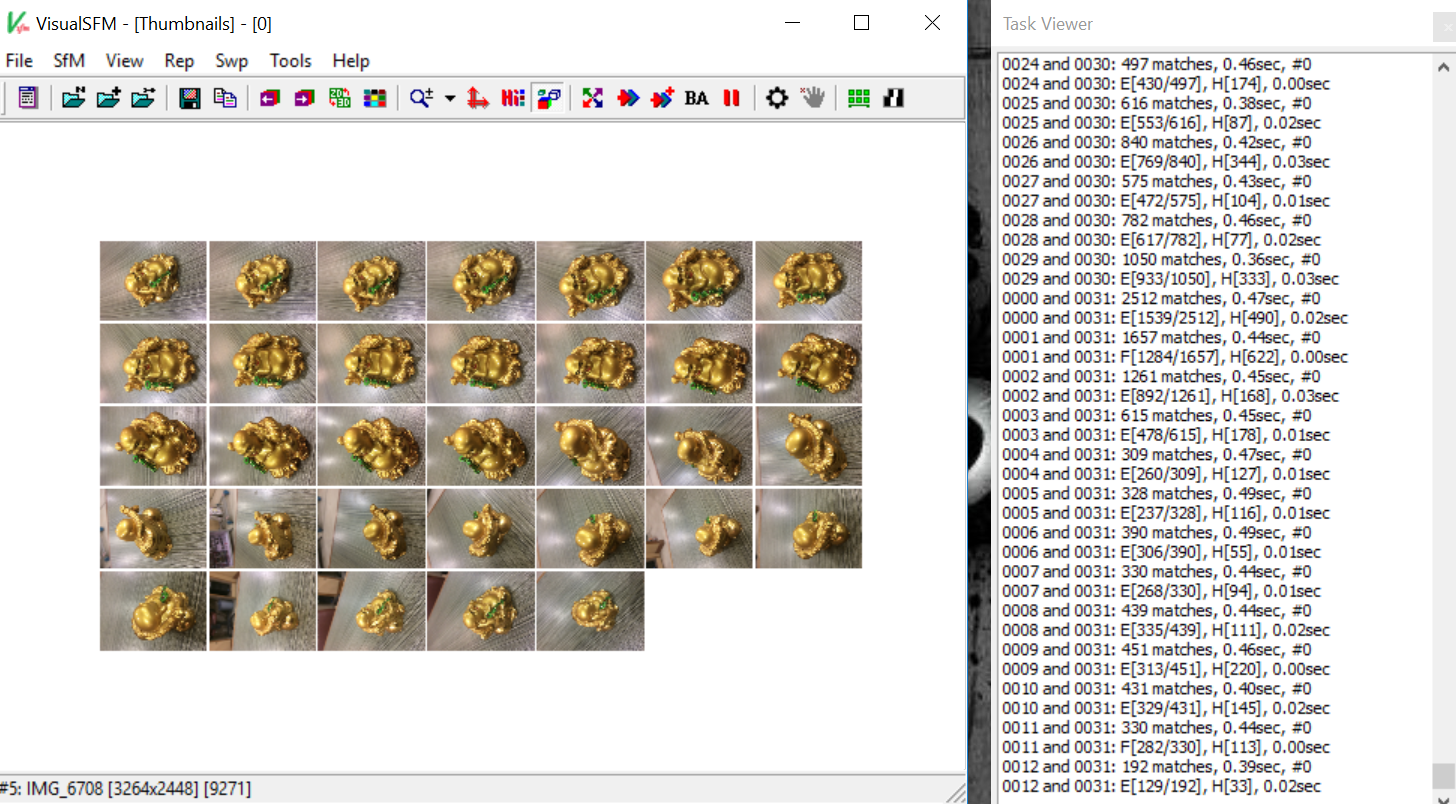
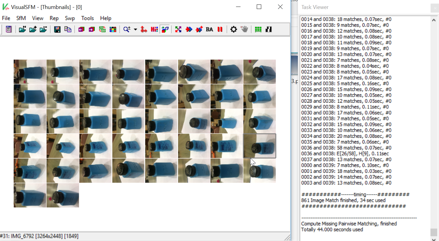
- Take around 100 pictures of the object need to be scanned and upload all those images on VisualSFm and start matching the specified pair with the specified buttom on the toolbar.
I did this with two objects as shown below.
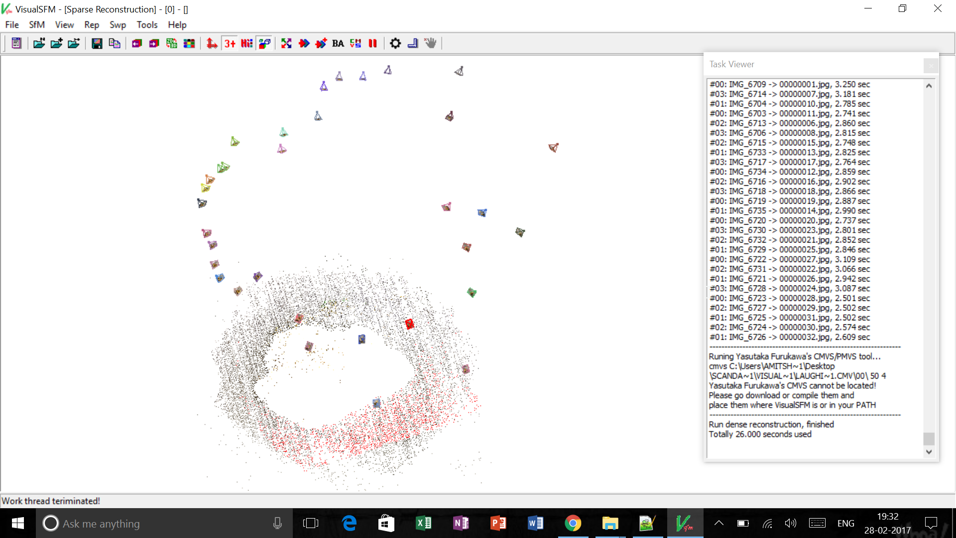
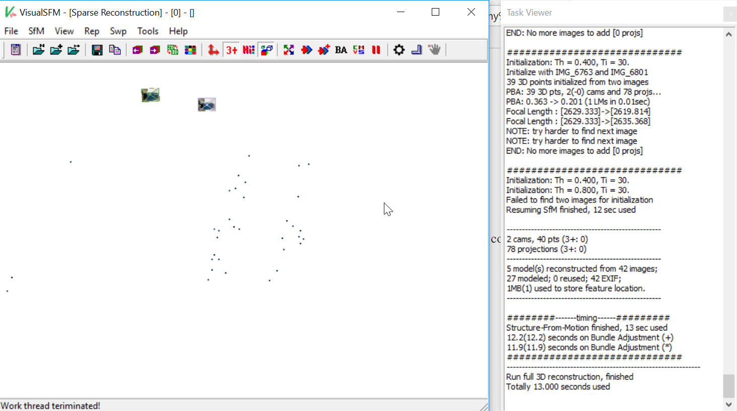
- Start Computing 3D Construction by the specified button on the toolbar. Once the 3D construction is computed u will see the point cloud data and save that file for further processing and refining on MeshLab.
- Open MeshLab, import the files and remove the unwanted and disturbing points from the scan.
Problems faced with VisualSFM and MeshLab
- The density of the points was very less, maybe because of incabability to the software to differentiate between the images and background.
- Since, the density of the points very less. Therefore, the obtained scanned image was not clear and thus we were getting nothing in dense 3D view.