Designing the board.
I used Eagle to design the board, the software was easy to use and look really neat. It wasn't my first time with designing pcp, but I normally do really simple thing and use a software call sprintlayout But since Eagle as been recomended to me from a lot of people I decide to try it.
First thing I did was to go and download the fabacademy library (fab.lbr) Once the library was download I insert it in my Eagle lbr folder :
![]()
After loading the library I went inside it using the add command and import every component I needed for my board. I add a led a resistance and a button from the basic components of the helloboard as shown here:

Here is the list:
Attiny44
Ftdi Header
LED
Pressbutton
10k resistances
1 uF capacitors
499Omhs resistor
Then to link them I use two different method, I wanted the schematics to be clean so instead of link everything with a net trace I named my component and label them using the name and label command so they could be link with their names.
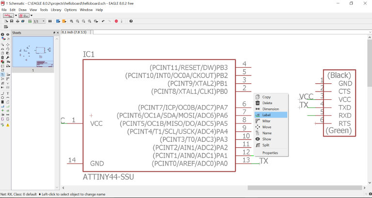

While the components that was near each other, I just used the normal net trace function and link them together.
Once everything was in order Here what it looks like:

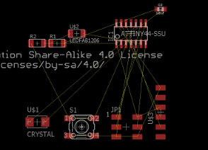
I then made the board by pressing the button Generate/Switch to board. Everything was messed up, but it was all there.

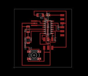
At first, I use the route function and try to make the trace by myself, it is possible but it's quite time conssuming, and it's like a puzzle, this is for a really simple board, I can't imagine for when our board will get more complex, so I didn't lose time and decided to try the autorouter tool. So First I needed to set my parameters into the DRC Tool. To make sure that the space between my trace would be ok, I set a space a bit bigger than the one between the pad of the attiny.
And I gave a with of 25mil for the interior of my traces.


I then start the autorouter tool and let the magic happen!

Setting the rule for my DRC was pretty simple and straighforward, you just need to make sure that your trace aren't too thin or too thick and thats pretty much it. Inside the autorouter, you have to specify that you want a one layer PCB, then you just have to launch it, it will try different options for your traces and will tell you the percentage of completion of paths on every option so you can choose the better one, for a simple board such as the hello board it wasn't hard for it to find a 100% option.
Once the board was done, I export it as a png and import it into
inkscape
I vectorize the png image and draw a contour for my cutout.


Finally, I save the two files (board and cutout) ans an SVG and import it into the fabmodules for milling.
![]()
![]()
Designing PCB's is really fun and I totally fell in love with eagle, favorite week so far!
Milling the board
Milling the board went pretty well, I just use the default parameters for the 1/64 outline pcbmilling inside the fabmodules and
save the gcode. I also always take a look at the Gcode juste to make sure everything is in place and that the z-axis does'nt
goes too deep. My new CNC at home doesn't have a automatic Z homing, so I simply use a papersheet to
adjust the distance for my zeroing.
< insert image here >
I find out that there is a command inside a G-code call T# this is a tool selection command, you can organize your tool by number and then the code will call them when necessary, I wonder if I could do it with my machine controller, I'd have to look into that. In the mean time, I have to generate two separate jobs, one for the trace and the other one for the board outline, I change my tool before starting the second job.
![]()
I also find that using v-bit shape tool instead of endmill makes a perfect job and dosen't break like 1/64" endmills often do.
![]()
Using the default Fabmodules parameters work great, but the feed rate is really slow, I will start to make test in my settings to see if I can accelerate the process. Using V-Bit, it may be possible to work faster on the machine.
Soldering the board
Soldering PCB's can be frustrating, when your mind is not quite at it, it can seem really difficult. It may seems dumb, but I find out that having a glass of wine or a beer before soldering can help with staying relax and patient with your component.
Alays work with a good soldering Iron, and don't be afraid to take break if you starting to get impatient, listen to music or find a way to be as relax as possible. Soldering is like meditation, it's quite hard to get into the right mind set, but once your in it, everything is amazing. Always work with good light and everything will be allright.
Here are some photos of the process:
![]()
![]()