ELECTRONIC : design

Here's our assignment:

x redraw the echo hello-world board
x add (at least) a button and LED (with current-limiting resistor)
x check the design rules, make it, and test it
It would be impossible to accurately describe how long this assignment was. Not much the steps I will describe below about designing the board but mostly debugging it. Let's dive in!
Adding a library to Eagle
Placing components BOM
Using Eagle on my mac, I added the Fab Library to access the components. I have some experience with Eagle. Enough to be able to spread my many components and create links between them. Here's the BOM
Circuit being cadded HTML tutorial Now entering the pcb mode
This is quickly shaping up Here's the almost completed circuit Now it's time to switch to pcb layout and create the bus
Errors generated
Properly bussed circuit Back to cad
I'm having trouble optimizing the layout by hand. I tried autoroute but it's a mess and would take longer to try to correct. That my first attempt at routing it. After realizing some components were not connected properly, I return to the layout mode to make corrections
Errors log in Eagle
Rework of busses
HTML tutorial
Oups. Clearance errors. Lot of them. My second attempt at routing clears all routing errors Can you see?
HTML tutorial
Exporting the results IN MONOCHROME!
2
Making that thing
So to produce the actual circuit on a Roland SRM20 Micro Milling machine, I need to edit the file in Inkscape, add a logo, check the routes and use fabmodules.org to produce the .rml file
Post-Export in Inkscape
Board ready to machine Milling on the SRM20
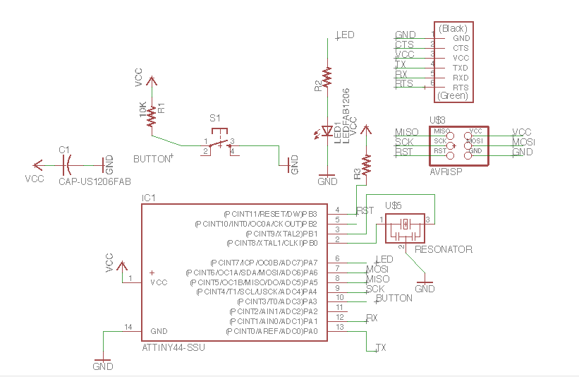
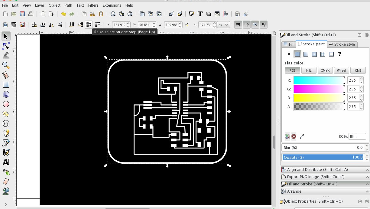
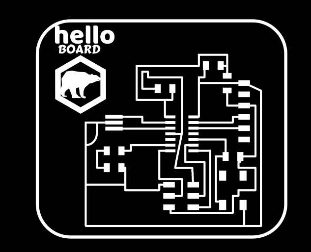
So in Inkscape, I add a logo and check my file. Everything is fine.. 
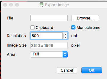
Here's a screenshot of the 500dpi image I will use in Fab Modules (see below) 
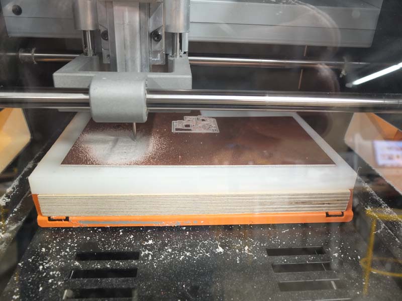
Once the .rml created by Fab Modules, I use the Roland control software to zero the machine and start the process.
HTML tutorial HTML tutorial HTML tutorial
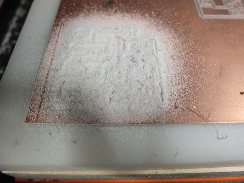
20000rpm + cutting tool = dust 
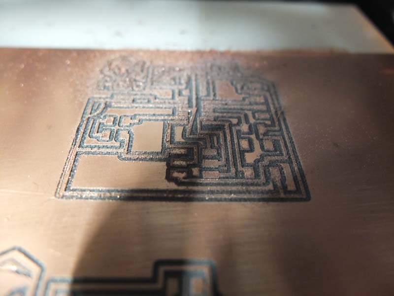
Here's the 1st attempt, I will make 3 in total The board once cutted by the 1/32 grinding tool. I used a saw to correct my design.
HTML tutorial HTML tutorial HTML tutorial
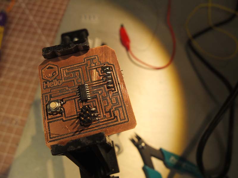
Now soldering the first components. I like to starty with the Attiny and then proceed to the smaller components. Here you go! 
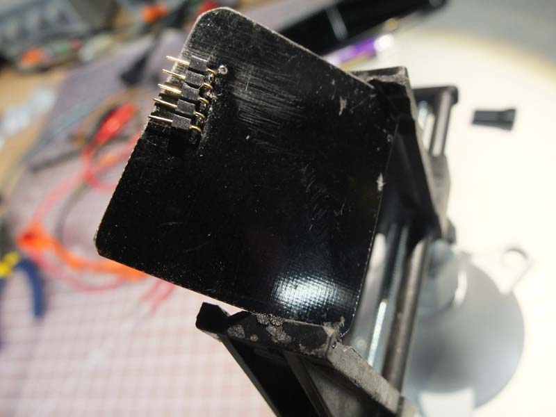
View from under to look the the pinout
HTML tutorial HTML tutorial HTML tutorial
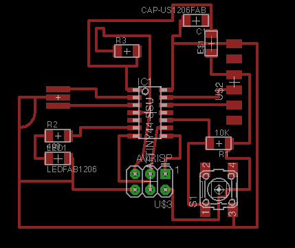
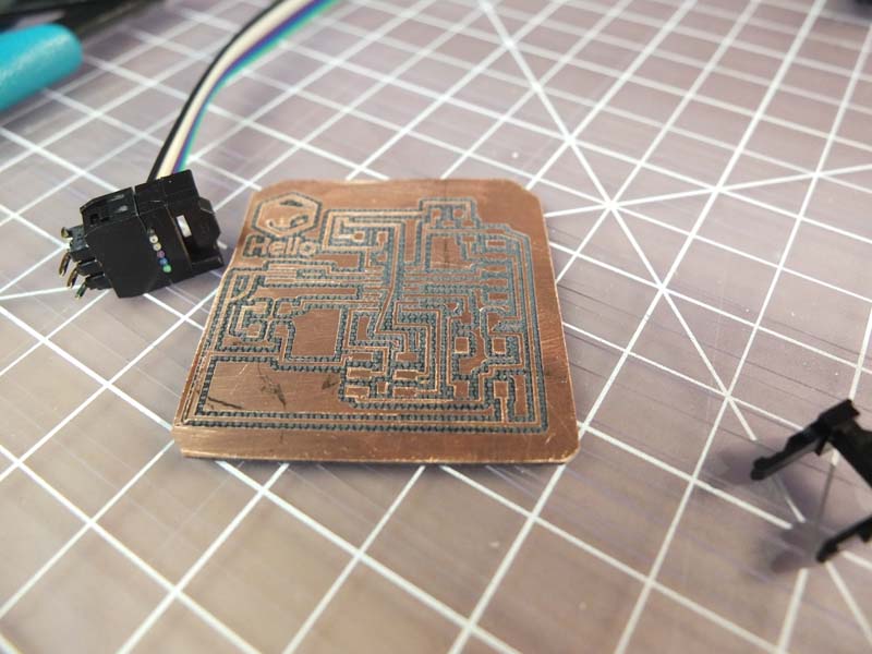
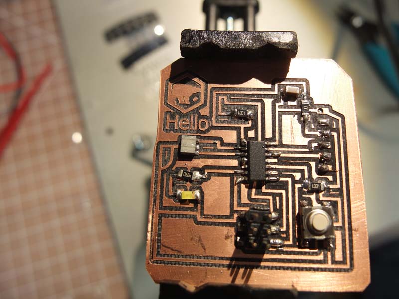
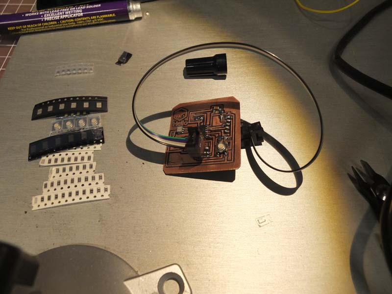
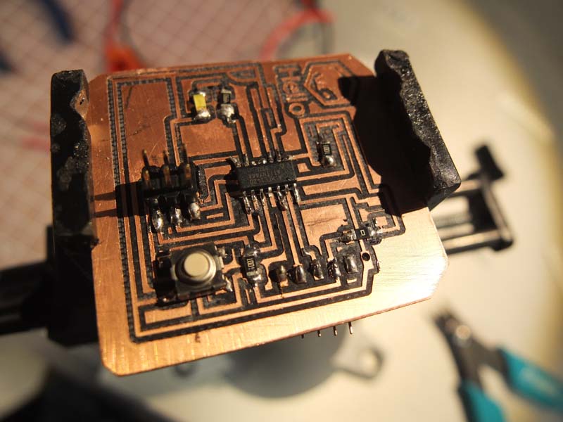
Completed board. I also made a 6pins cable. Better view from the top. 
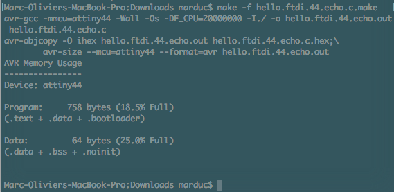
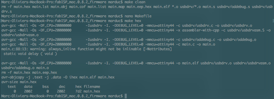
Now starting the fuse process. Here I'm running the make command to build the c program.
HTML tutorial HTML tutorial HTML tutorial
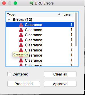
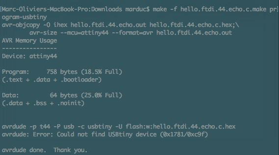
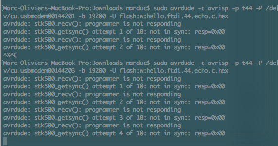
Getting a bunch of errors.
HTML tutorial HTML tutorial HTML tutorial
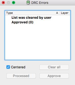
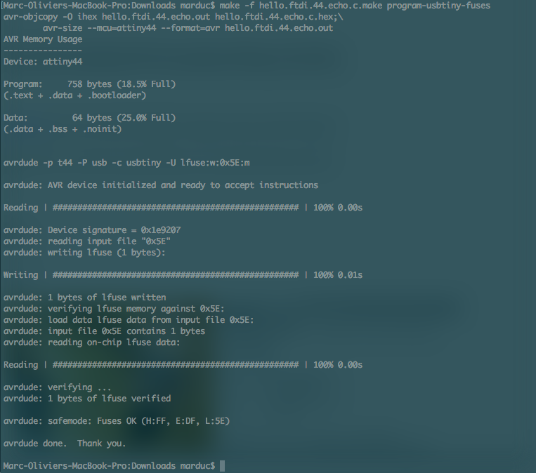
It does look quite nice. 
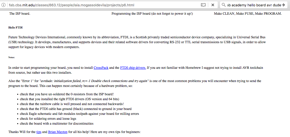
Laia's page was quite helpful in resolving my issues. I'm now able to profram my board!
HTML tutorial HTML tutorial HTML tutorial
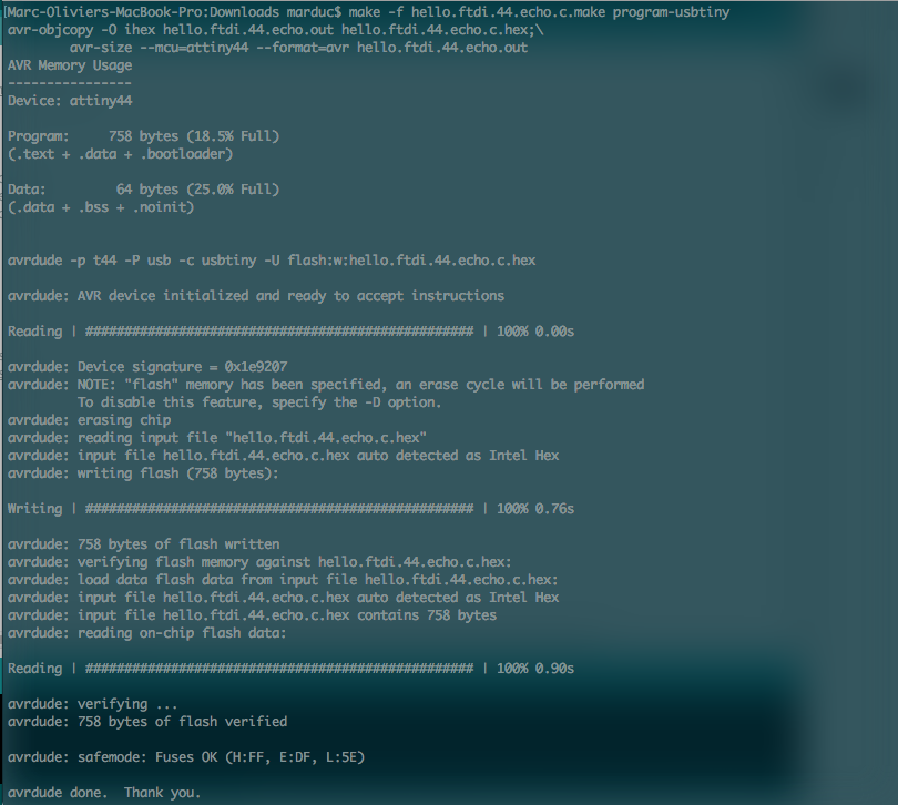
Sorry this image won't crop properly. But I was finaly successful in writing to my board. It was an issue with my FabISP. 
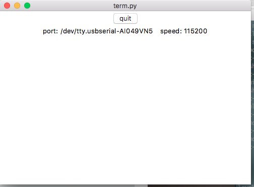
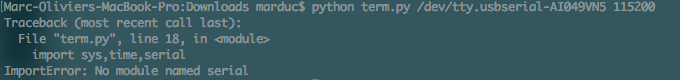
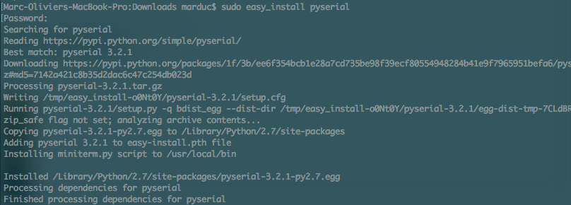
Now trying to lauch pyserial 
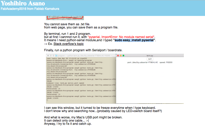
I found the tutorial by Yoshihiro Asano the best ressource to resolve my pyserial problems. Thanks man.
HTML tutorial HTML tutorial 
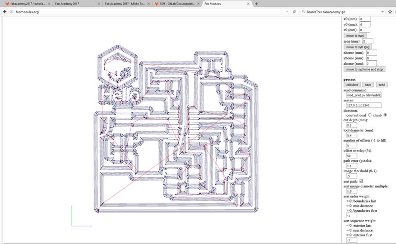
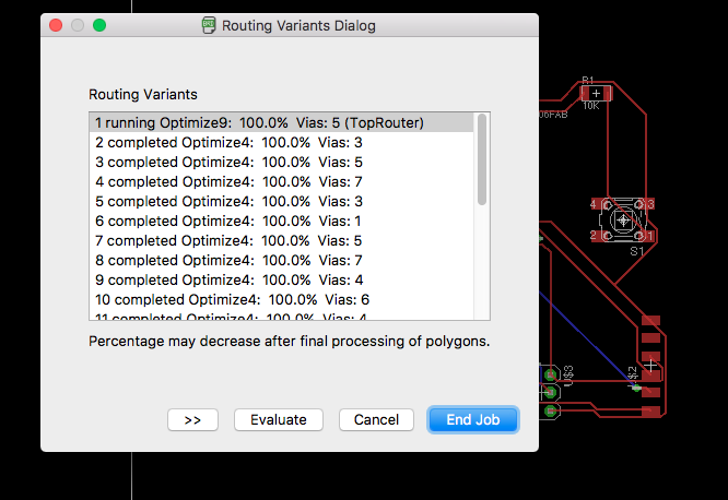
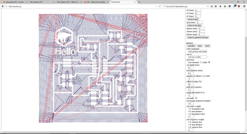
So I made two attempts to produce a viable RML file for the SRM20. The first one removed all material but was way to long, so I reduced the number of offsets (-1 to fill): to 5. That was much more acceptable.
Here you'll find the
|Asset Files
Link to my 2015 archive for more electronics stuff.
File
Week6_Assets_compressed.zip