Assignment
- Make lasercutter test part(s), varying cutting settings and slot dimensions
- Cut something in the vinylcutter
- Design, make, and document a parametric press-fit construction kit, accounting for the laser cutter kerf, which can be assembled in multiple ways.
Personal objectives
- Learn how to use an image vectorizer like Inkscape
- Learn the procedure to stablish the parameters of cutting in a laser cutter machine
- use the vinyl cutter to create an sticker
- Create a parametric design to create an assembly model of a desk lamp
Lasercut tests
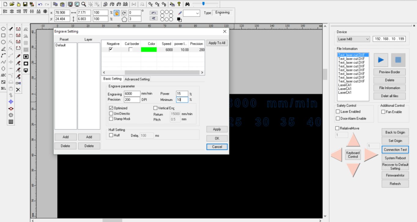
Before using the lasercut is a very good idea to test the parameters in order to understand the changes and the possibles
outcomes when a laser cut machine. For this purpose I try first the engraving parameters first with a set of fixed speed and precision,
and then varying the power of the laser.
The speed is set in mm/min, the precision of the engraving in dpi, and the power is measure in percentage of the maximum laser power.
The tests was made in MDF of 3 mm thickness with the next parameters:
| Speed | Precision | Power | |||||||
|---|---|---|---|---|---|---|---|---|---|
| 6000 mm/min | 200 dpi | 5 | 10 | 15 | 20 | 25 | 30 | 35 | 40 |
| 300 dpi | 5 | 10 | 15 | 20 | 25 | 30 | 35 | 40 | |
| 7000 mm/min | 200 dpi | 5 | 10 | 15 | 20 | 25 | 30 | 35 | 40 |
| 300 dpi | 5 | 10 | 15 | 20 | 25 | 30 | 35 | 40 | |
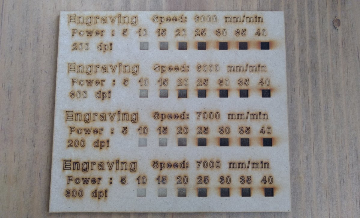
Results
- As can be seen in figure 2, an obvious statement is that the power affects the tone of the engraving. This can be useful for an artistic work, where several tones are needed.
- The speed (at least with these two sets) was not an influent factor in the results. It’s necessary to test with higher velocities.
- The precision setting affects the deep of the engraving, This factor has to be set depend on the thickness of the material.
- It is necessary to try more set of parameters and different materials with different techniques.
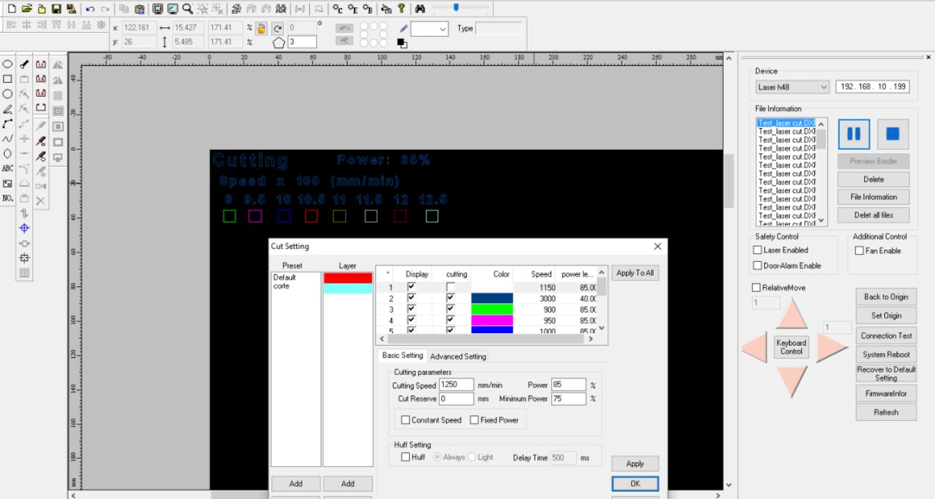
In a similar way the parameters for cutting were tested. The parameters
to try this time were speed (mm/min) and power (%). First and the power were fixed a 85 % and the speed were tested in a range of 900 to 3000 mm/min.
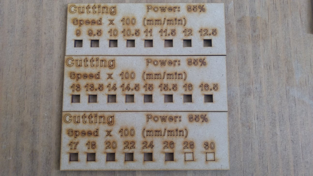
It was found that with a power of 85% the speed could be up to 2600 mm/min. However after 2000 mm/min,
is necessary to push the cut in order to remove. That’s why I chose a 2000 mm/min speed for the varying power test. (Fig. 5)
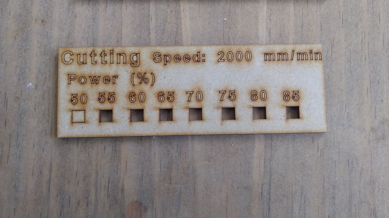
With a fix speed of 2000 mm/min the power were tested from 50% to 85% and it was found that even a 55 % power the cut is clean, but again at 55%
it was necessary a push to remove the cut piece.
As a conclusion the parameters to cut 3mm thickness MDF are: power: 60% and speed: 2000 mm/min.
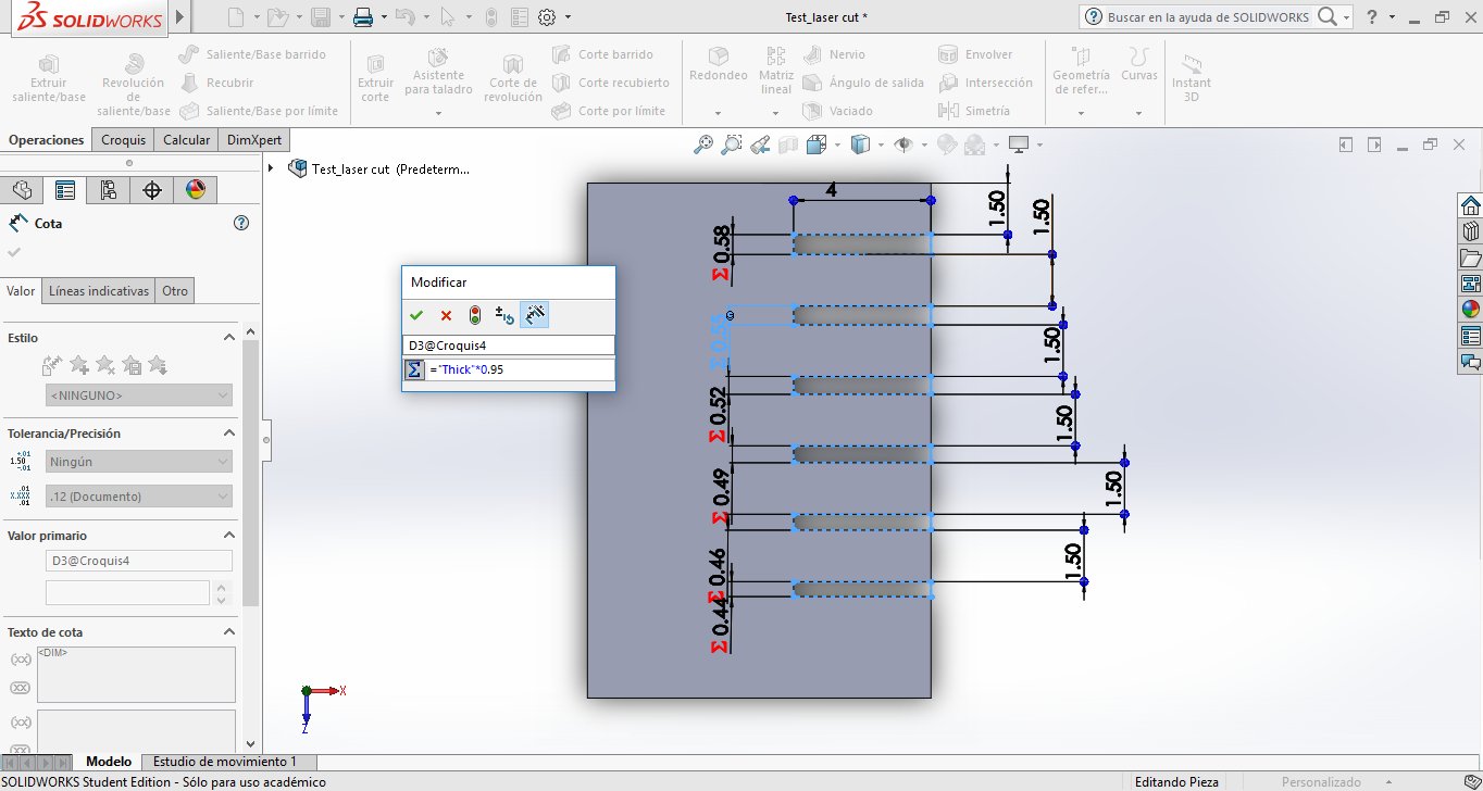
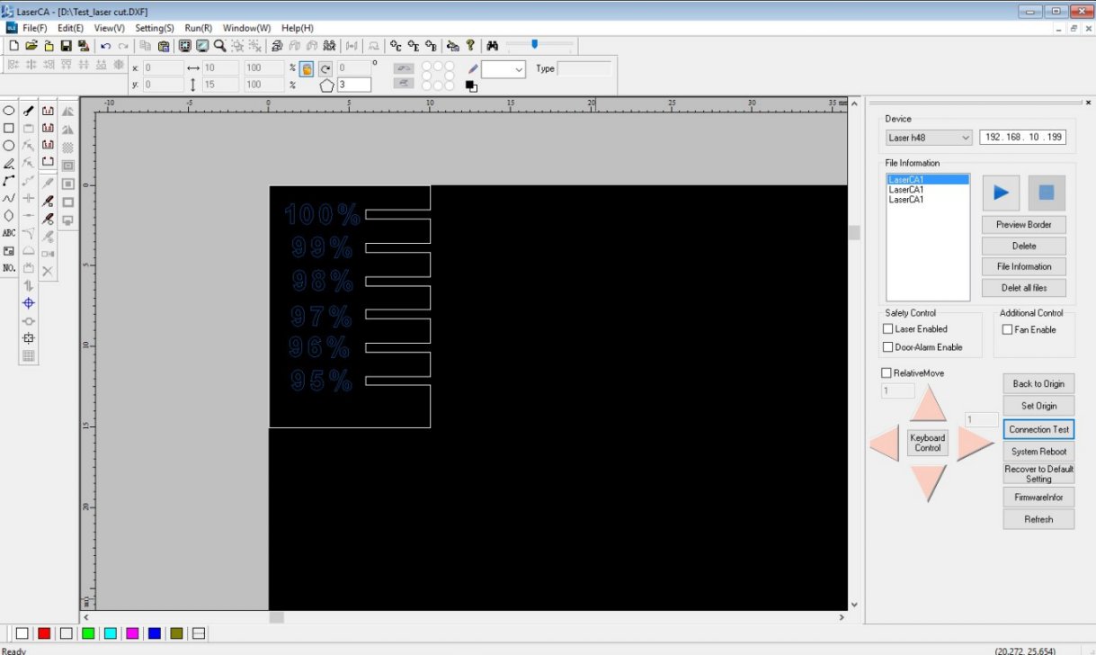
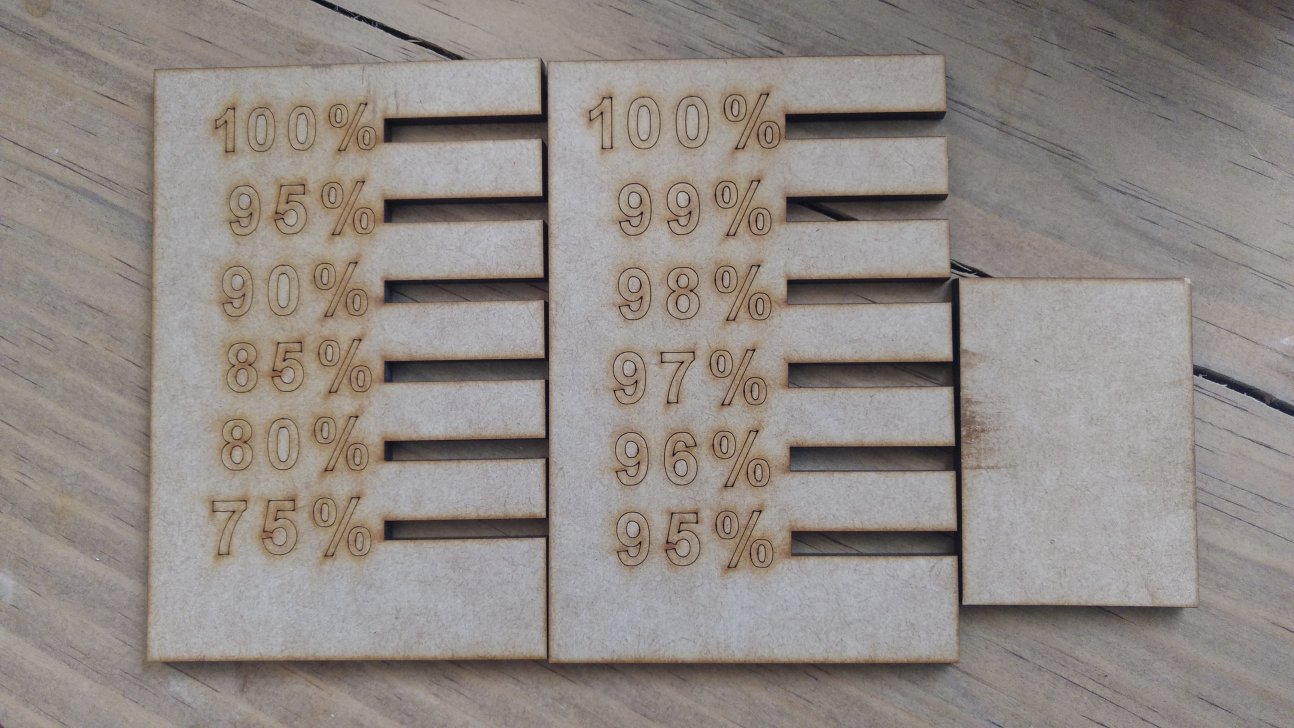
For a press fit model is necessary to test the joints between the different parts. That’s why I made a test consisting in a test different joins with a reduction in percentage of the thickness of the MDF. First I use a reduction from 100% to 75 % in steps of -5% at a time. This was clearly an exaggeration because at 95% reduction the fit was to tight. That’s why a second test was made between 100% and 95% with steps of 1%. With this test it was found that a reduction of 4 % in the thickness for joints is a good point for a press-fit model. Gives the possibility to assemble and disassemble the model without compromise the integrity of the pieces.
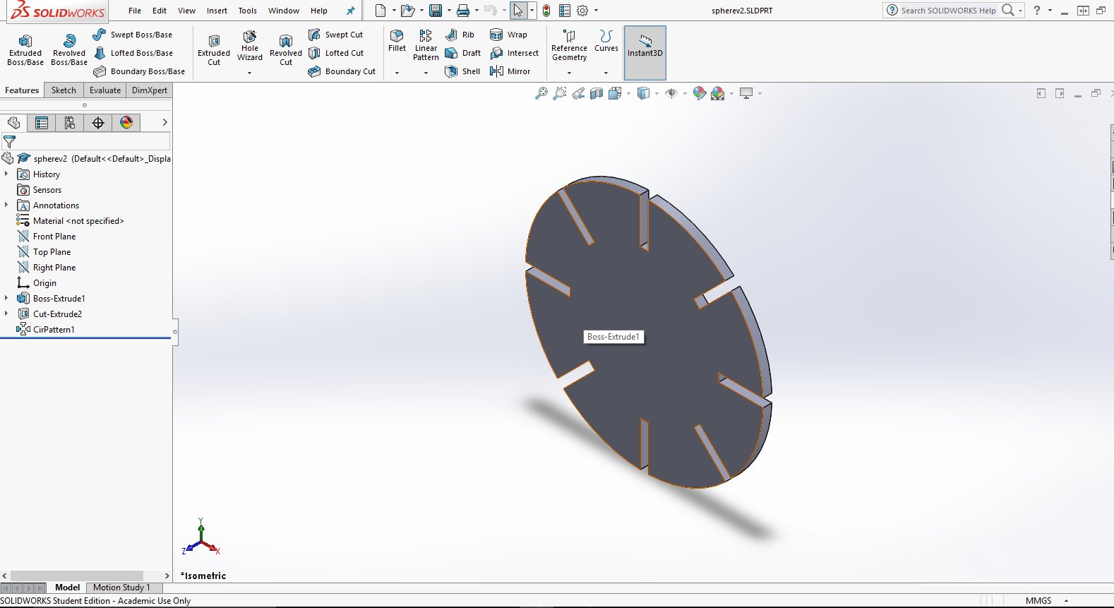
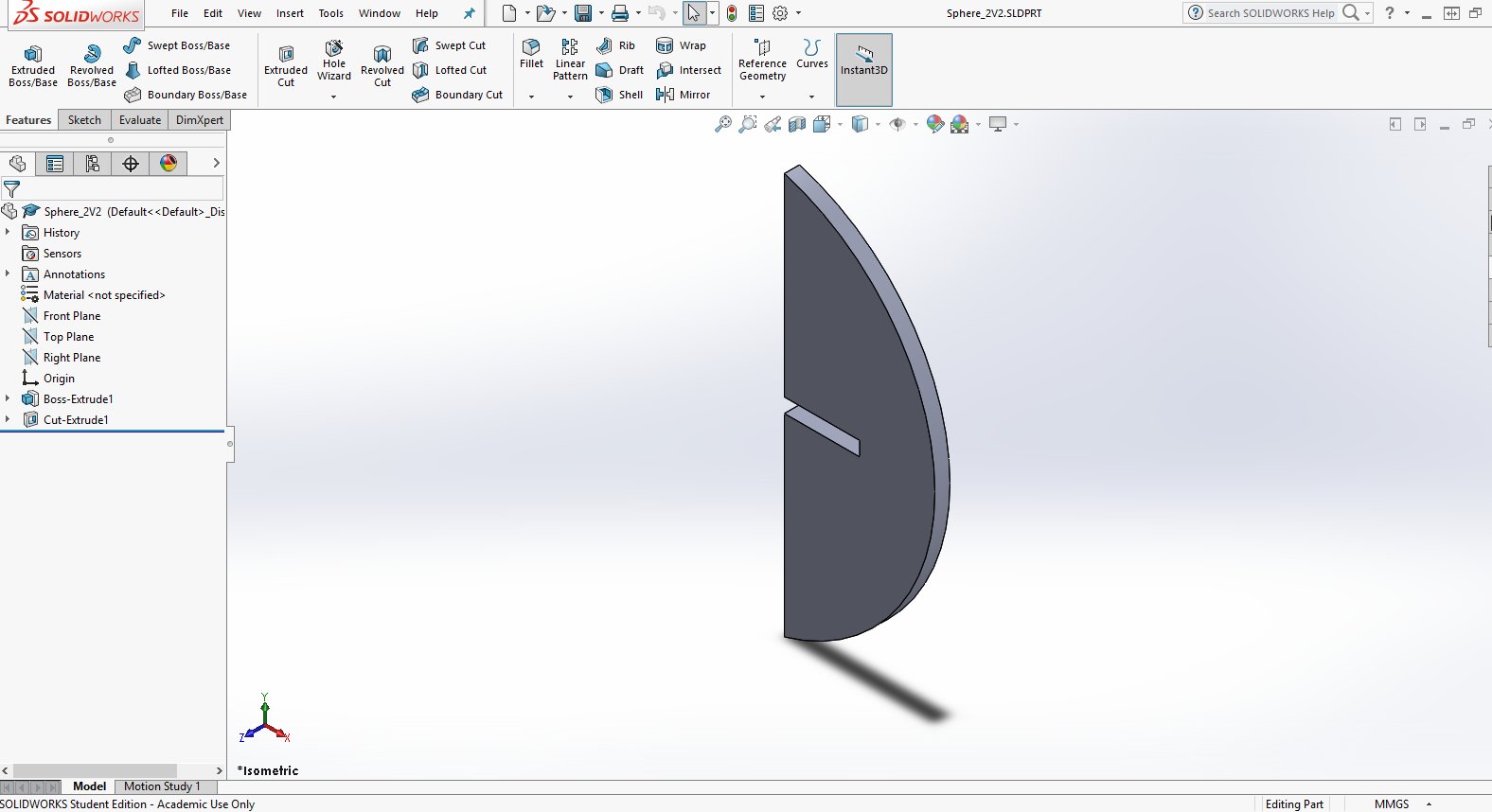
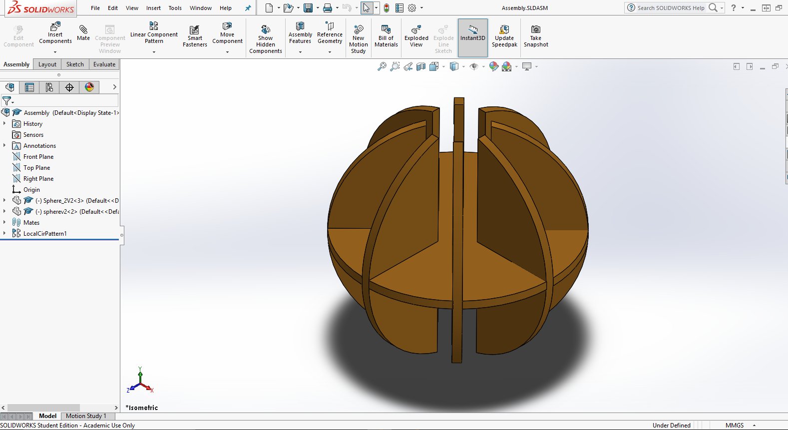
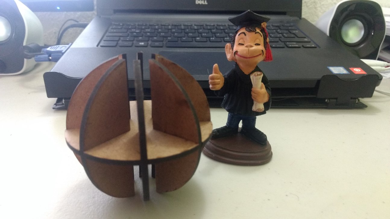
press-fit models
Files
In this section the files generated during the development of the assignment will be available to download

|
|
|
| Sphere_Part_1.SLDPRT | Sphere_Part_2.SLDPRT | Sphere.SLDASM |
