Assignments
Embedded programming
So for this assignment I will have mostly two weeks. I will profit it to finalize my board and to developed it in different ways. Here is my TODO for this 2 weeks. Green = done. Details will become when I will post some code.
- DONE: Read DataSheet
- To read data sheet of AVR Attiny44
- BLK: Cut my board
- To cut my board that I will programm
- BLK: Solder board
- Solder and programm it
- DONE: C straight
- In C I will develop controller behavior in straight way. It will permit to validate functionality of controller board and the workflow.
- DONE: C + interrupt
- I will develop button behavior to be attached to interrupt that will permit me to separate behavior of button from behavior of LED.
- DONE: ASM
- I will develop ASM based code
- DONE: C + Serial
- I will develop C code with serial communication.
Read datasheet
Oh yes... I read it a lot. Because of simple mistake in Interrupt programming I tested a lot of things and I used a lot datasheet for the Attiny44 (same as Attiny44A that we use for the echo hello-world board, but with a little more power consuming in some modes. The doc of difference between them I also read.)
Cutting and soldering board
I am blocked with cutting and soldering board. My CNC router built, but... one of stepping motors is dead. It just vibrating and making strange sound, but not turning. It is not linked to problem with controller shield, nor with arduino, neither with cables or drivers. So I contacted vendor, but because of Easter I am not sure to have his feedback until Tuesday / Wednesday. So no way to cut my "echo hello board" right now. Re-scheduled for +2 days. Video of crappy motor is located here
C program that use straight processing to manage key push
Let start from simple. I use for development Arduino IDE and 123D circuit. As hardware it use simple Arduino nano connected via USB and emulator in 123D circuit. C straight code permit add some behaviour to button and LED. It is as well accessible via simulator here. I did it previous week but I will reuse it here. When board will be ready I will push this code to attiny controller. Now it just pushed and tested with real Arduino UNO.
  int led = 0; // we use port 0 for our LED
  int button = 1; // button is connected to port 1

  void setup() {
    // initialize the digital pin as an output.
    pinMode(led, OUTPUT);
    pinMode(button, INPUT);
  }

  void loop() {
    if (digitalRead(button)==HIGH){  // read state of button and check if pushed
      digitalWrite(led, HIGH);   // LED is on
      delay(300);               //  wait for 300ms.
    }
   digitalWrite(led, LOW);    // turn the LED off by making the voltage LOW
   delay(300);               // wait for 300ms
  }
C program that use interrupt to react on key push
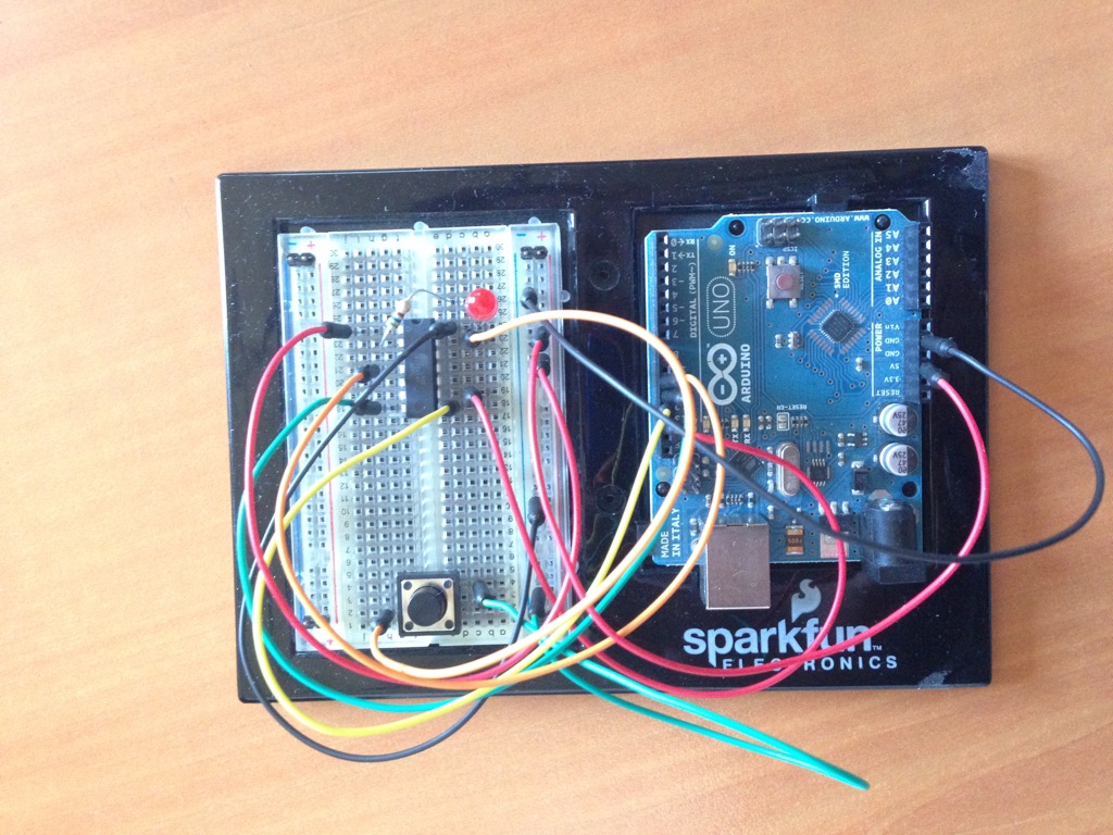
This is my installation of attiny44 connected to its programmer based on Arduino ISP. Button and LED are connected in same way as on my HelloBoard.
Let improve simple C code and pass to interrup. Development was done under the X-Code / Crosspack / X-Avr as development environment. To deploy my code I will use gcc-avr avrdude on software side and aruino uno with Arduino-ISP patched sketch (reduced speed to 9600bod and fixed sync-error problem) and attiny44 on prototyping board with passive components. The sketch required for this is available in all media files zip as "isp.ino".
Fuse happens at 5V with speed 9600 using following command:
$ avrdude -pt44 -cstk500v1 -P/dev/cu.usbmodem* -b9600 -U flash:w:main.hex:i
That means that we push to attiny44 using the stk500v1 programmer (arduino uno with sketch is detected like this), using the any ports that it uses now (it may change after disconnection) and we push main.hex to atting (w option) as the hex ascii text.
Makefile that I have used for builds is below.
# Name: Makefile
# Author: <insert your name here>
# Copyright: <insert your copyright message here>
# License: <insert your license reference here>

# This is a prototype Makefile. Modify it according to your needs.
# You should at least check the settings for
# DEVICE ....... The AVR device you compile for
# CLOCK ........ Target AVR clock rate in Hertz
# OBJECTS ...... The object files created from your source files. This list is
#                usually the same as the list of source files with suffix ".o".
# PROGRAMMER ... Options to avrdude which define the hardware you use for
#                uploading to the AVR and the interface where this hardware
#                is connected. We recommend that you leave it undefined and
#                add settings like this to your ~/.avrduderc file:
#                   default_programmer = "stk500v2"
#                   default_serial = "avrdoper"
# FUSES ........ Parameters for avrdude to flash the fuses appropriately.

DEVICE     = attiny44
CLOCK      = 8000000
PROGRAMMER = -cstk500v1 -P /dev/cu.usbmodem1411 #-c stk500v2 -P avrdoper
OBJECTS    = main.o
#avrdude -pt44 -cstk500v1 -P/dev/cu.usbmodem1411 -b9600 -U flash:w:sketch_mar27a.ino.tiny14.hex:i
FUSES      =  -b9600 -U flash:w:main.hex:i #-U hfuse:w:0xd9:m -U lfuse:w:0x24:m

# ATMega8 fuse bits used above (fuse bits for other devices are different!):
# Example for 8 MHz internal oscillator
# Fuse high byte:
# 0xd9 = 1 1 0 1   1 0 0 1 <-- BOOTRST (boot reset vector at 0x0000)
#        ^ ^ ^ ^   ^ ^ ^------ BOOTSZ0
#        | | | |   | +-------- BOOTSZ1
#        | | | |   +---------- EESAVE (set to 0 to preserve EEPROM over chip erase)
#        | | | +-------------- CKOPT (clock option, depends on oscillator type)
#        | | +---------------- SPIEN (if set to 1, serial programming is disabled)
#        | +------------------ WDTON (if set to 0, watchdog is always on)
#        +-------------------- RSTDISBL (if set to 0, RESET pin is disabled)
# Fuse low byte:
# 0x24 = 0 0 1 0   0 1 0 0
#        ^ ^ \ /   \--+--/
#        | |  |       +------- CKSEL 3..0 (8M internal RC)
#        | |  +--------------- SUT 1..0 (slowly rising power)
#        | +------------------ BODEN (if 0, brown-out detector is enabled)
#        +-------------------- BODLEVEL (if 0: 4V, if 1: 2.7V)
#
# For computing fuse byte values for other devices and options see
# the fuse bit calculator at http://www.engbedded.com/fusecalc/


# Tune the lines below only if you know what you are doing:

AVRDUDE = avrdude $(PROGRAMMER) -p $(DEVICE)
COMPILE = avr-gcc -Wall -Os -DF_CPU=$(CLOCK) -mmcu=$(DEVICE)

# symbolic targets:
all:	main.hex

.c.o:
	$(COMPILE) -c $< -o $@

.S.o:
	$(COMPILE) -x assembler-with-cpp -c $< -o $@
# "-x assembler-with-cpp" should not be necessary since this is the default
# file type for the .S (with capital S) extension. However, upper case
# characters are not always preserved on Windows. To ensure WinAVR
# compatibility define the file type manually.

.c.s:
	$(COMPILE) -S $< -o $@

flash:	all
	$(AVRDUDE) -U flash:w:main.hex:i

fuse:
	$(AVRDUDE) $(FUSES)

# Xcode uses the Makefile targets "", "clean" and "install"
install: flash fuse

# if you use a bootloader, change the command below appropriately:
load: all
	bootloadHID main.hex

clean:
	rm -f main.hex main.elf $(OBJECTS)

# file targets:
main.elf: $(OBJECTS)
	$(COMPILE) -o main.elf $(OBJECTS)

main.hex: main.elf
	rm -f main.hex
	avr-objcopy -j .text -j .data -O ihex main.elf main.hex
	avr-size --format=avr --mcu=$(DEVICE) main.elf
# If you have an EEPROM section, you must also create a hex file for the
# EEPROM and add it to the "flash" target.

# Targets for code debugging and analysis:
disasm:	main.elf
	avr-objdump -d main.elf

cpp:
	$(COMPILE) -E main.c
Below is the program that first of all make setting on ports PA0 to be in input state. To have pull-up resistor activated on it, to have external interrupt activated on it as well. Then we have interrupt vector linked to small subroutine that change status of one variable from 1 to 0 and inverse. Inside main loop we do blinking LED on PB0 with 100ms delay / light periods and in case if volatile variable is changed (to 0) we change frequency of blinking to 500ms phases.
  #include <stdio.h>
  #include <avr/io.h>
  #include <avr/interrupt.h>
  #include <util/delay.h>


  #ifndef cbi
  #define cbi(sfr, bit) (_SFR_BYTE(sfr) &= ~_BV(bit))
  #endif
  #ifndef sbi
  #define sbi(sfr, bit) (_SFR_BYTE(sfr) |= _BV(bit))
  #endif


  volatile int blinkdelay=1;

  /*

                                   VCC     GND
   (PCINT8/XTAL1/CLKI)             PB0     PA0 (ADC0/AREF/PCINT0)
   (PCINT9/XTAL2)                  PB1     PA1 (ADC1/AIN0/PCINT1)
   (PCINT11/RESET/dW)              PB3     PA2 (ADC2/AIN1/PCINT2)
   (PCINT10/INT0/OC0A/CKOUT)       PB2     PA3 (ADC3/T0/PCINT3)
   (PCINT7/ICP/OC0B/ADC7)          PA7     PA4 (ADC4/USCK/SCL/T1/PCINT4)
   (PCINT6/OC1A/SDA/MOSI/DI/ADC6)  PA6     PA5 (ADC5/DO/MISO/OC1B/PCINT5)
   */

  // GIMSK:   - INT0 PCIE1 PCIE0 - - - -
  // PCMSK1:  - - - - PCINT11 PCINT10 PCINT9 PCINT8
  // PCMSK0:  PCINT7 PCINT6 PCINT7 PCINT4 PCINT3 PCINT2 PCINT1 PCINT0


  int main(void)
  {
      cbi(DDRA, PA0);   //Turn port A0 as input
      sbi(PORTA, PA0);   // Pull-up resistor activated on PA0
      sbi(GIMSK,PCIE0);
      sbi(PCMSK0,PCINT0);
      sei();                 // enables interrupts
      sbi(PORTB, PB0);

      for(;;){
          if(blinkdelay==1){
              sbi(PORTB, PB0);
              _delay_ms(100);
              cbi(PORTB, PB0);
              _delay_ms(100);
          } else {
              sbi(PORTB, PB0);
              _delay_ms(500);
              cbi(PORTB, PB0);
              _delay_ms(500);
          }
      }
      return 0;
  }

  ISR(PCINT0_vect)
  {
      if(blinkdelay==1){
          blinkdelay = 0;
      } else {
          blinkdelay = 1;
      }

  }
After testing this code I found that changes of state of button may happens twice during one execution of the interrupt vector subroutine. So the behavior may changed on pushed button vs. released. It could be fixed by adding read current button state in interrupt vector code subroutine.
Assembly code
I decided to some Assembly code. So simple blink is looks enough for the beginning. I used macro assebler - so quiet simplified version of it. I won about 10 times in size of code (30 words that were pushed and works). To build I used avra macro assemberl compiler. In the left window you can see Makefile I used for this and in the right - the code itself. Fuse done via Arduino UNO in Arduino ISP mode to ATTiny44. As delay I used count from 1 to ~1 000 000 - so I have about 4 blinks per second.
              MCU=attiny44
              TARGET = portb_led1
              ASRC = $(TARGET).asm

              AS = avra

              AVRDUDE = avrdude

              AVRDUDE_PROGRAMMER = stk500v1 # Using arduino uno and arduino ISP

              AVRDUDE_PORT = /dev/cu.usbmodem*

              AVRDUDE_WRITE_FLASH = -b9600 -U flash:w:$(TARGET).hex

              AVRDUDE_BASIC = -p $(MCU) -P $(AVRDUDE_PORT) -c $(AVRDUDE_PROGRAMMER)

              AVRDUDE_FLAGS=$(AVRDUDE_BASIC)

              all:
              	$(AS) $(ASRC)

              program:
              	$(AVRDUDE) $(AVRDUDE_FLAGS) $(AVRDUDE_WRITE_FLASH)
.include "tn45def.inc" ; Using attiny45 definitions as closest

.def count_l = r16   ; counter for low values
.def count_h = r17   ; counter for large values
.def count_vh = r18   ; counter for even larger values

    sbi DDRB, DDB0  ; define pin 0 of port B as an output port

main_loop:
    sbi PORTB, PORTB0	; led on
    rcall delay		; wait a bit
    cbi PORTB, PORTB0	; led off
    rcall delay		; wait a bit
    rjmp main_loop	; and cycle

; This routine delays the program by counting from 1 to 1048576
delay:
    ldi count_l, 0
    ldi count_h, 0
dec_loop:
    dec count_l
    brne dec_loop
    dec count_h
    brne dec_loop
    inc count_vh ; Let have very-high bits to be inverse increased up to 4
    cpi count_vh,4
    brne dec_loop
    clr count_vh ; let clear very-high bits here just to do it in different way
    ret ; back to main loop where we have call for delay
C program that open Serial communication and react on commands
Now let do some communication via Serial code. I used Arduino nano for this. Code below open Serial communication and when receive command ON - switch the LED on. Any other commands switch the LED off. This way may probably be used for the next week assignment, if we will need to have a program that manage our machine.
#include <string.h>

#define MAX_BUF (64)
char buffer[MAX_BUF];
int sizeIn;

void setup() {
  // start serial port at 9600 bps and wait for port to open:
  Serial.begin(9600);
  while (!Serial) {
    ; // wait for serial port to connect. Needed for native USB port only
  }


  pinMode(13, OUTPUT);
  establishContact();  // send a byte to establish contact until receiver responds
}

void loop() {
   while(Serial.available() > 0) {
    char c=Serial.read(); // Read next char

    if(sizeIn0 && (buffer[sizeIn-1]=='\n' || buffer[sizeIn-1]==';' )) { // End of line? Anything received?

    buffer[sizeIn]=0;  // End of command

    commandAnalyze();  // Analyze
    ready(); // Ready for next command

  }

  else if(sizeIn>0 ) {
    // No ; or newline?
     Serial.println("No end of command received. Please use ';' or newline in terminal setting");
     ready();
  }

}

void status() {
  Serial.println(F(""));
}

void sendOK() {
  Serial.println(F(""));
}

void commandAnalyze() {
  // We need analyze received command.
  if (!strncmp(buffer, "ON", strlen("ON"))){
      digitalWrite(13, HIGH);   // turn the LED on
      Serial.println("LED is ON");
  } else {
      digitalWrite(13, LOW);   // turn the LED off
      Serial.println("LED is OFF");
  }
  sendOK();
}

void ready() {
  sizeIn=0;  // Clean nb received chars
  Serial.print(F(">>>\n"));  // ready to receive input
}

void establishContact() {
  if (Serial.available() <= 0) {
    Serial.println("READY");   // send an initial string
    ready();
    delay(50);
  }
}
This video demonstrate how it works for terminal point of view. The LED of course is also switched on and off.