in this project assignement I make an fabisp(In system programmer) card that I will use in programming other PCB boards. I followed this tutorial to make this exercice which is pretty clear, I downloaded hello.ISP.44.traces.png and hello.ISP.44.interior.png in png format. I used fabmodules to convert png files to gcode mill traces with 1/64" and outline with 1/32" as described here and here I tried default offset and 10 offset then I used the machine interface to set XY, and Z axis and send the job to the cnc milling machine, unfortunately I lost the screenshots of job setting because of my bad hardisk that I replaced later, also I dont remeber tha name of machine control program I used, bellow is the video and photos I took during the session. Mohammed Naji in Fablab Casablanca assisted me in this exercice part.
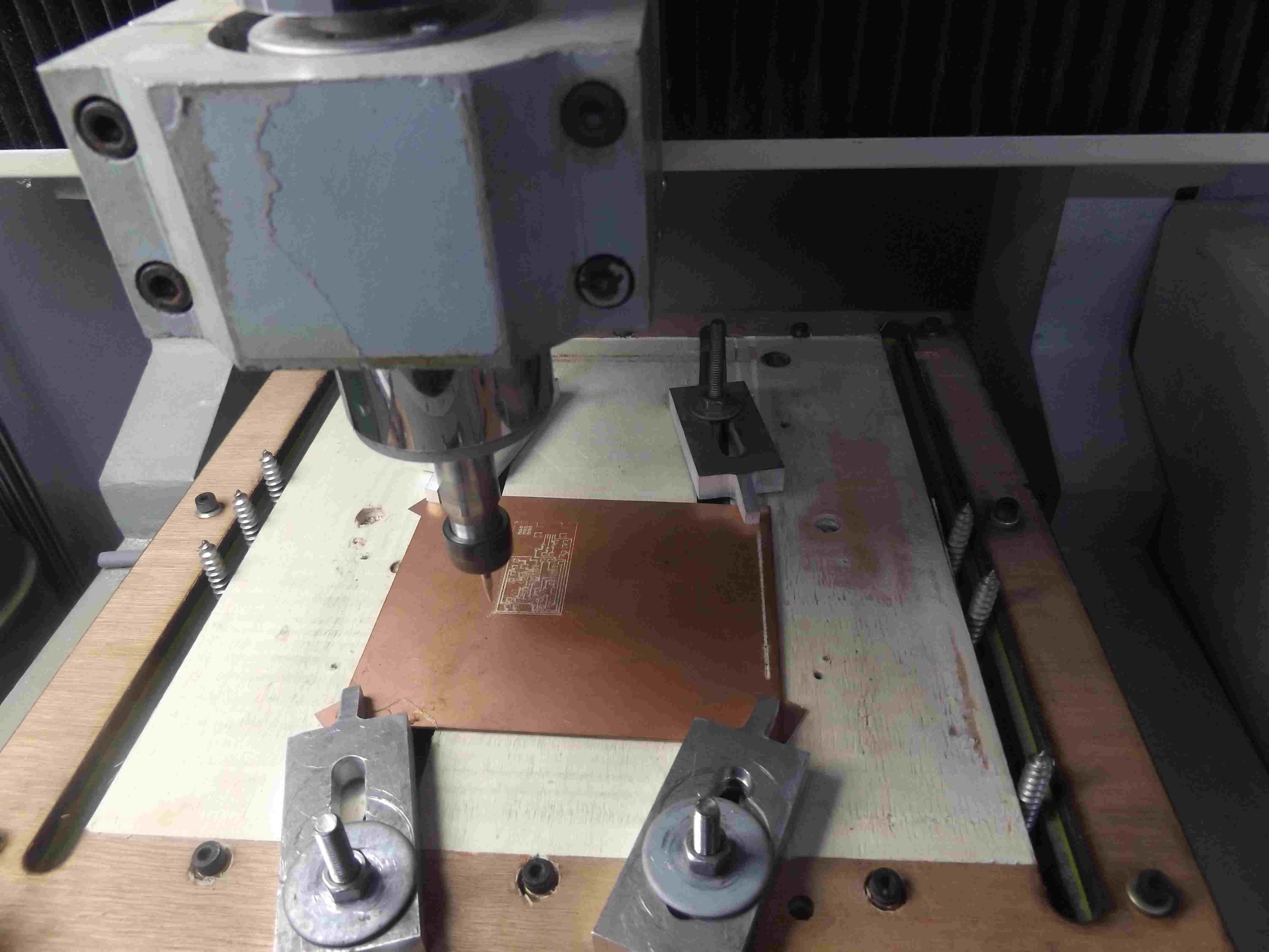
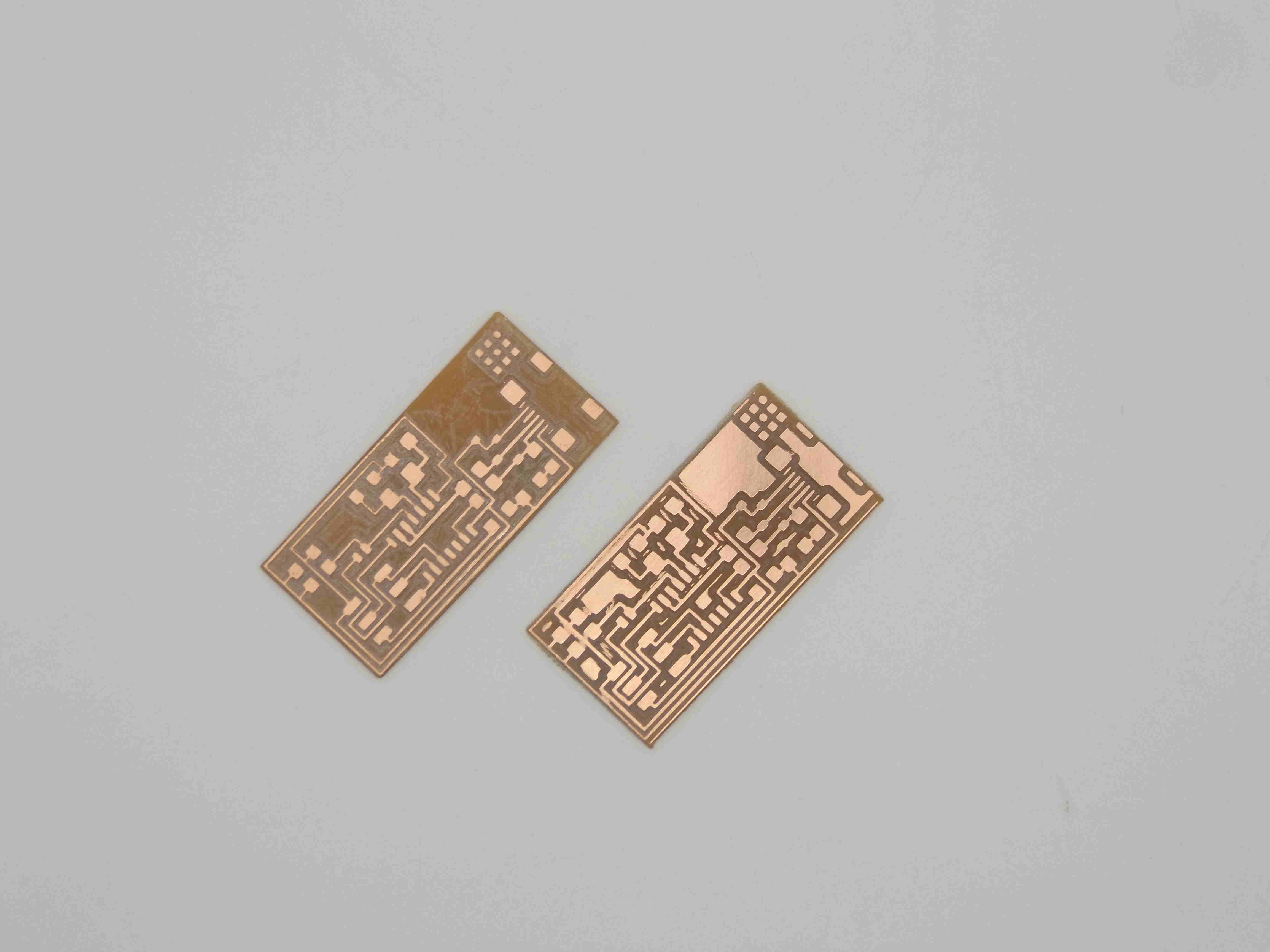
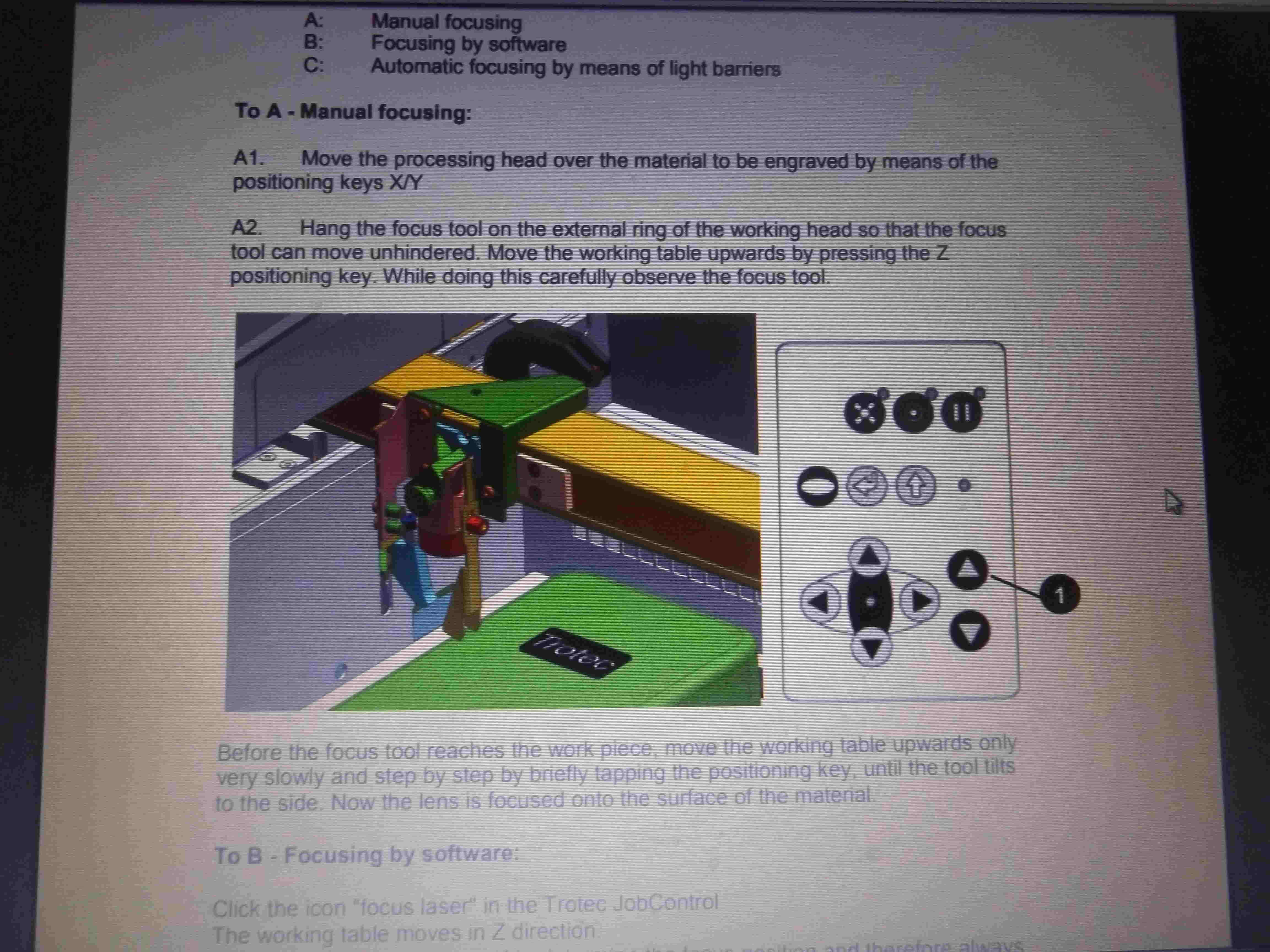
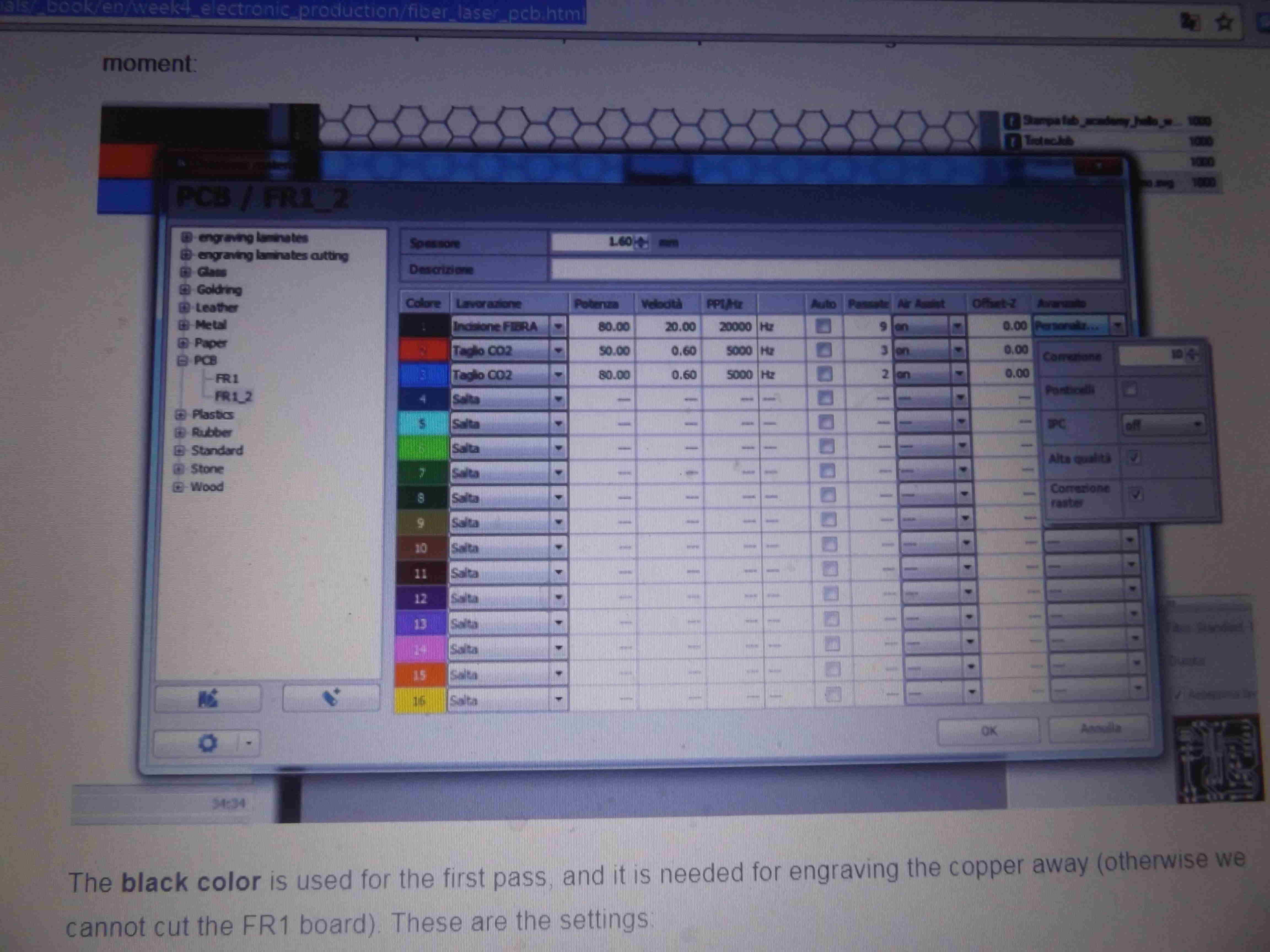
I needed to make this board again in opendot fablab because in my previous board I supposed to use 20MHZ crystal that is not available in opendot instaed I use 16MHZ resonator, in my second board I replace 20MHZ crystal and two 10PF capacitors with one 16MHZ resonator, I used the modified file of Ernesto. Matteo explain to me how to use the trotec Laser CO2. I followed this tutorial I prepare the file in Insckape and use to send the job to the machine, here the outline is in red color and I have one file to send to the machine, in insckape file properties I change page unit to inch then resize page to same height and width of the electronic card, landsacape format, I print to trolec, I choose X and Y, selecr and drug the card to the cross point on the screen which is the origin, I adjust the focus manually by focus tool nad Z positionning, see in the image below, if I loose focus during engraving process I can pause the job moving the working table upward a bit , then resume. I keep the same setting for power velocity and number of passes, on the tutorial find below the settings, video and photo of the second card
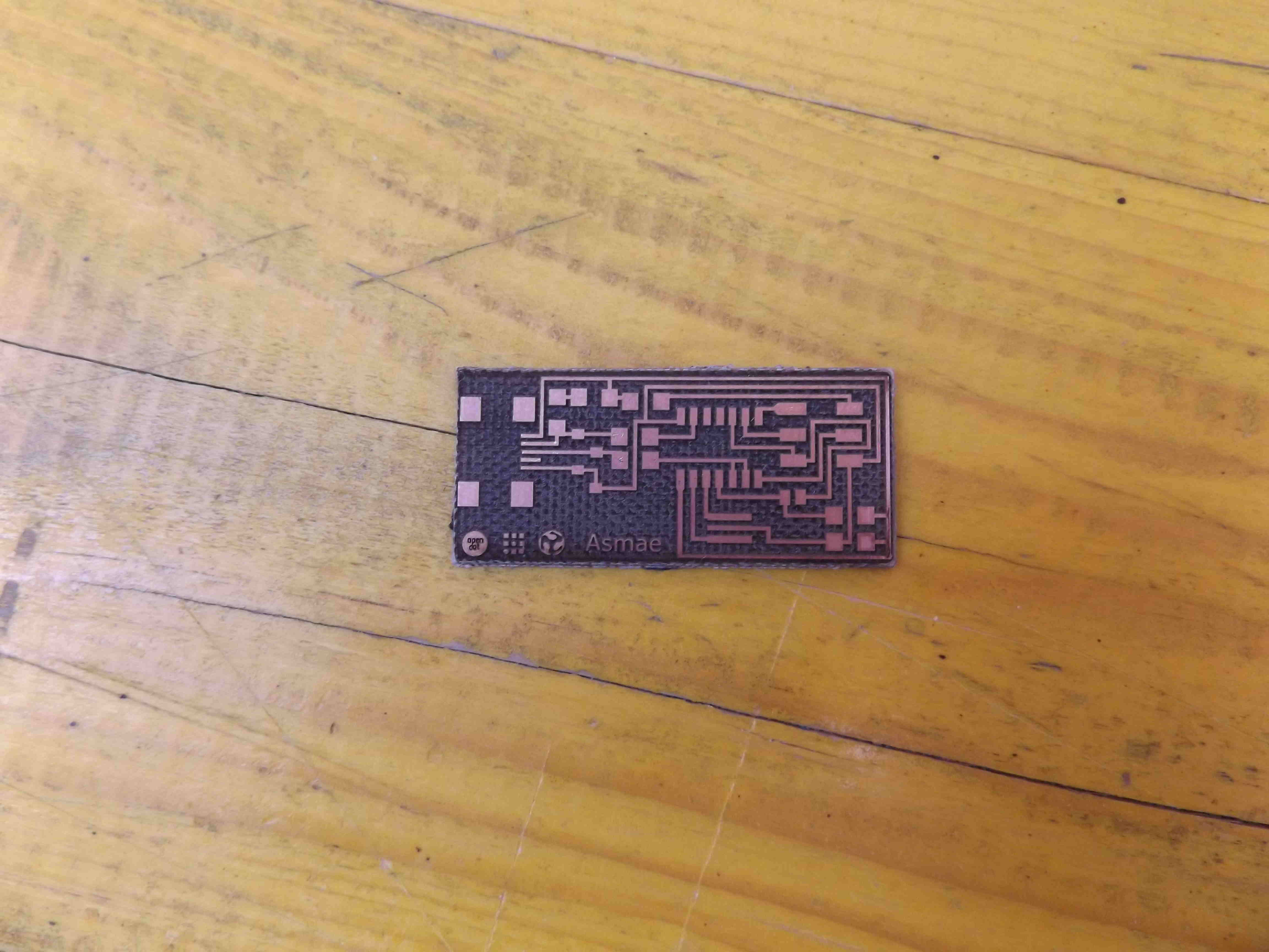
Ernesto and me did soldering with soldering iron, soldering paste, soldering fil almost 0.6 or 0.5 mm and desoldering with hot air, we soldered My first PCB board. I used 290 degree for both soldering and desoldering, as smd components are too small and I was shaking in the beginning, I made some bad connections when soldering MC I check connections connections with mulimeter, soldering and desoldering as necessary.

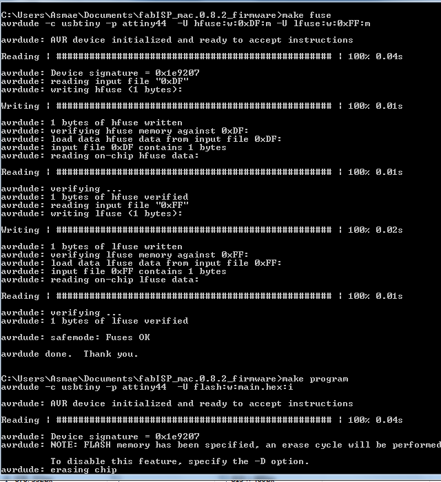
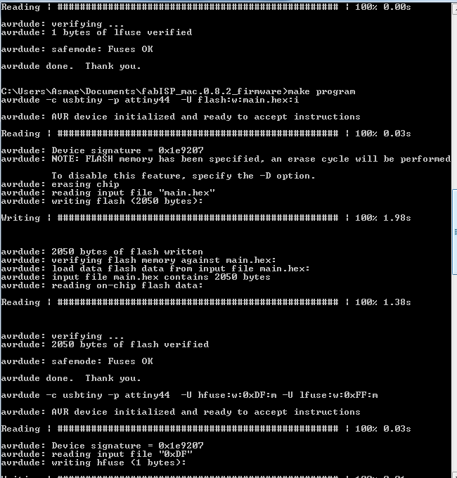
I followed this tutorial . I installed WinAVR on my machine usbtinyISP driver and fabisp firmware, then I install usbtinyISP driver. I plugged usbtiny programmer in 6pin header of Fabisp as in the picture. edit the makefile in the firmware with the programmer I used which is usbtiny its Enrico's programmer. I plug the two boards on my computer usb, then from command line in firware folder. I execute the commands make clean, make hex to compile the firmware, make fuse to set the fuses so the board will use external clock 16Mhz resonator in my case, and make program to program the board to be an ISP. when soldering this board by mistake I seem use a bit of conduction paste. I clean and dry very well later, during programming my mini usb brokes and needed to replace it, the new one was better, could not program the fuses, due to bad connection, so I double check each connecting point in the board and solder properly. here are the programing screenshots

 then I removed 0ohm resistor and solder bridge.
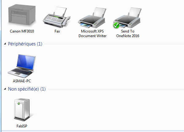
I use this fabisp to program my final project board, it stopped working and I get the message unknown device instead. I staff and program an other fabisp board but I get the same unkown device message, connections and programming are both correct, but I get problem with usbtiny driver. in some tests I got note on driver signature.