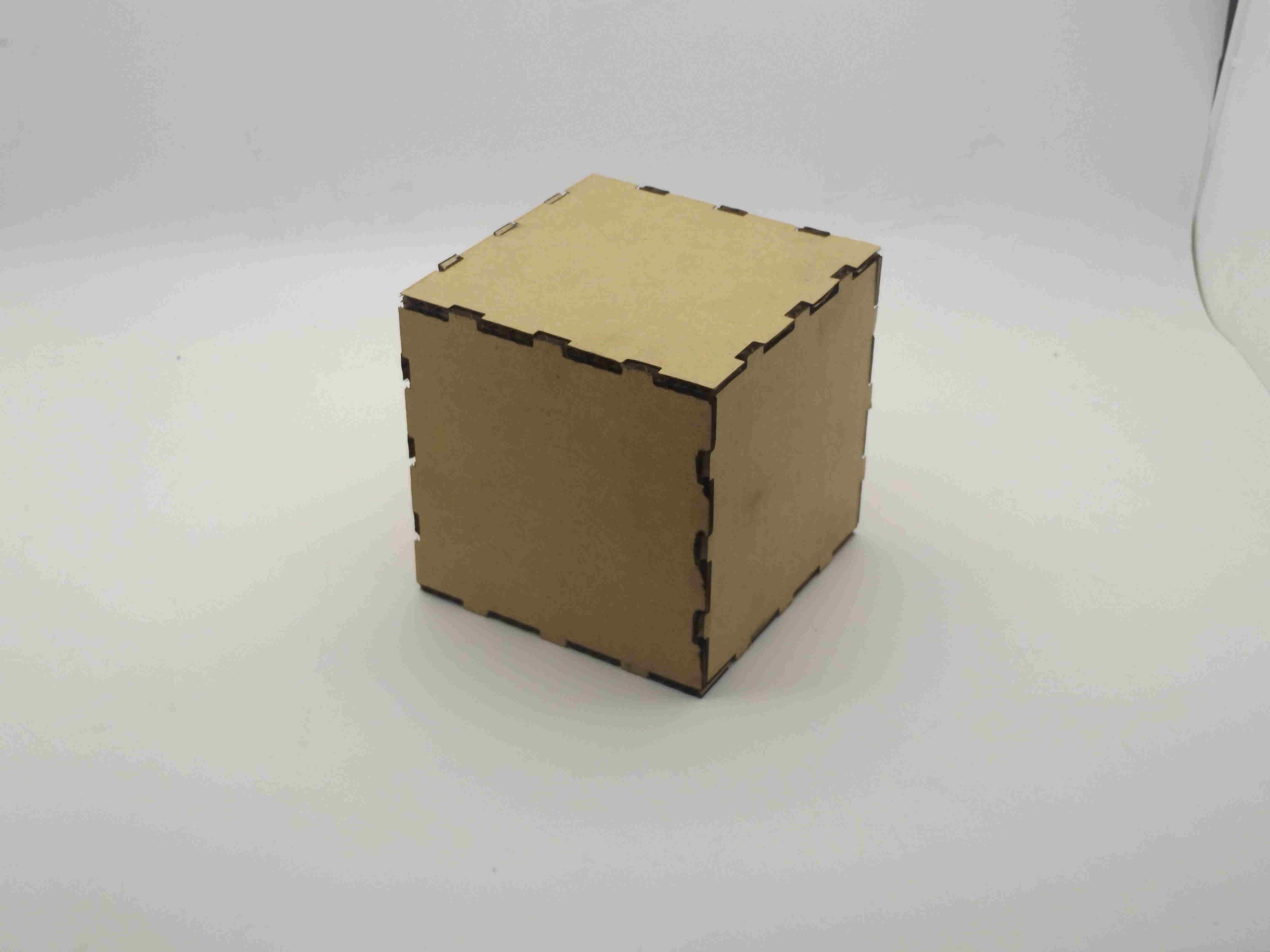
in this week assignment I will be sketching a press fit box in Inskape and cut the final result in laser cutter
sketching
pressfit box
Before I start drawing I set document properties, default units to mm and landscape format. adjust the page and zoom in/out as needed, set the outline, outline style thikness to 0mm, Im using cardboard to design pressfit box, depth of my material is 2.5 mm and measuring the kerf is 0.5mm
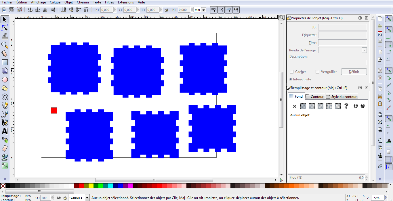
I draw the first box 10X10mm , tab 10X6mm, I make 3 clones of the tab align to the center according to the big object to place the first tab in on the lower edge of the box in the center, I then place the two others at equal distances from the first tab, I center horizenatlly the three tabs with the help of a line that I put on the lower edge, then I clone and group the three tabs, to place to the three other edges, I aligned the group to the center of each edge according to the big object and align horizetally two times for the both sides and vertically on the top with the help of a line that i draw on the top of each edge to get precise part, this way I drawed the face/back of the box I cloned 3 times, one for the back, one for the other left/right and one for the top/bottom then each part has to be doubeled by either copy/clone for the sides of the box or copy/paste for the top/bottom
to make the left and right I apply the difference on right and left edges on the cloned box, I detach the clone and ungroup then I apply difference under path menu and copy/clone one time the face resulted to make (left and right faces), the make the top/bottom of the box, I detach the clone and degroup as necessary, I apply difference on the four edges of the box, then copy/paste to make 2 faces(top and bottom)
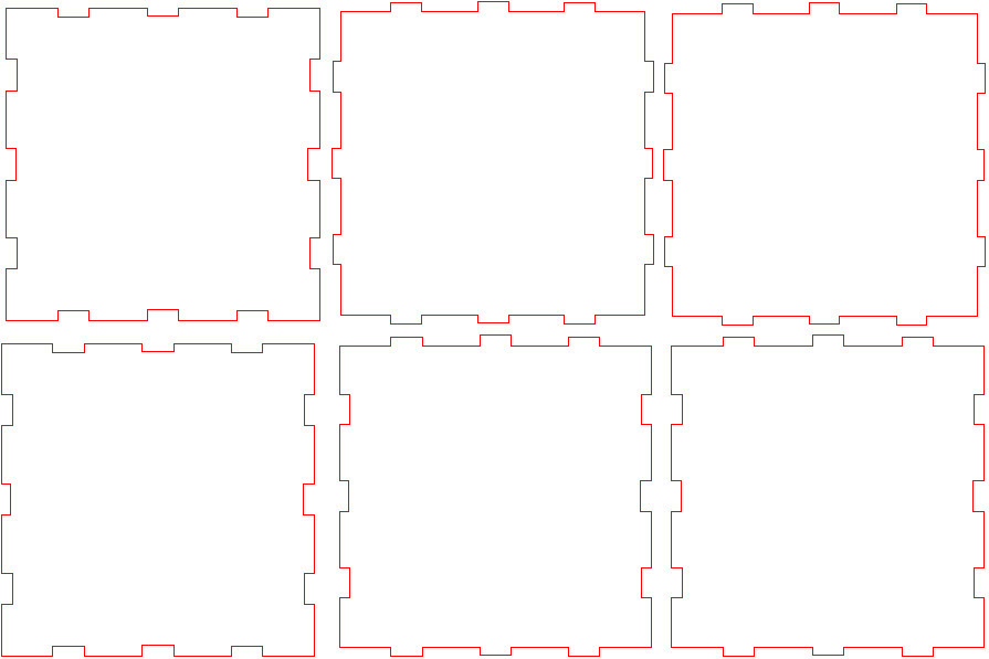
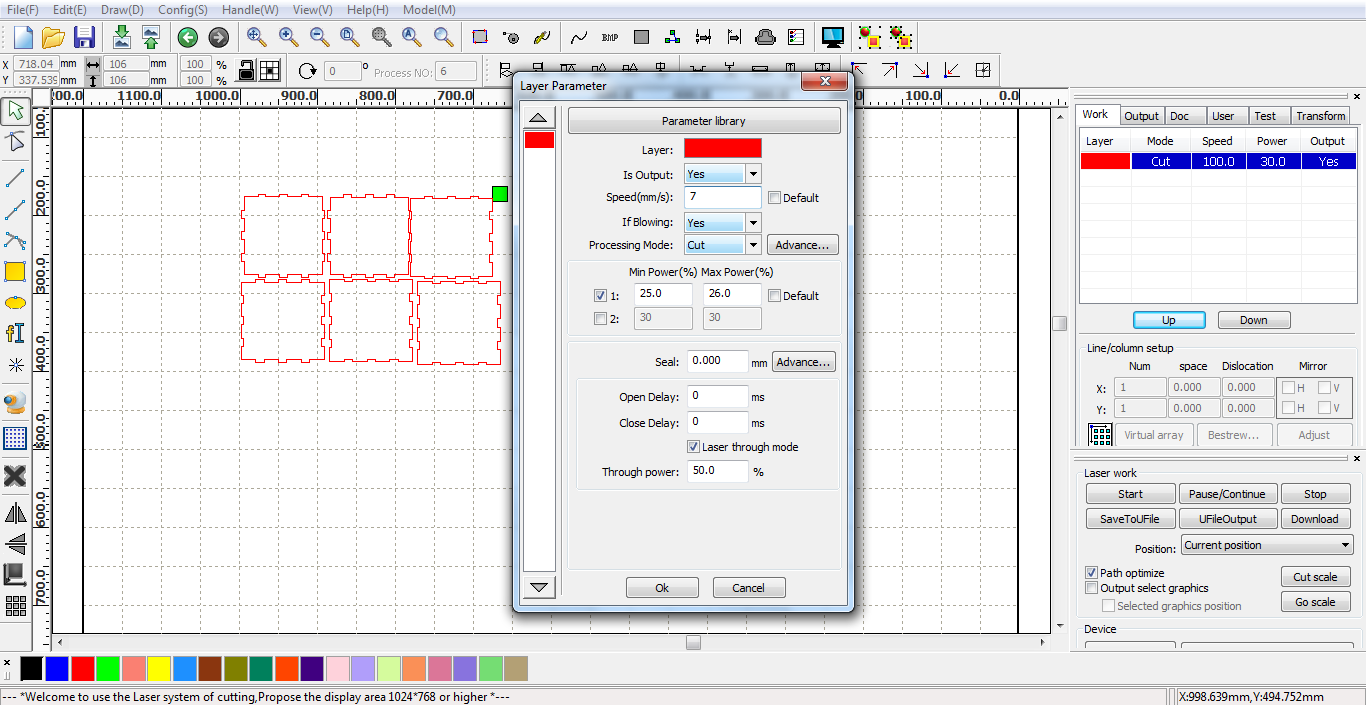
now before I apply union to the tabs in the sides of the box, I consider the kerf which is 0.5 in stroke I add weight of 0.5 mm and check its application in all tabs, then I detach the clones degroup and apply path union. now as we have the 6 sides of the box before senting to the laser cutter, I apply again stroke of 0.5 weight on all parts with color red and no background color these are the lines/paths I use RDWorksV8 software to prepare the file to the laser cutter. I open RDWorksV8 import dxf file check for witdth and height and fix the size I usually need to fix this when importing dxf files from Insckape, because the parts I get on RDWorksV8 are smaller, check every part size I have them on red color and 0.5mm in stroke, in the top right in work layer I choose red color for cut because I want these parts cutted.
I set red color layer to cut, I organise the parts in order to not have waste material during the cutting process.
speed 7
min power 25
max power 26 then OK to confirm, I then click on save to Ufile. this will on usb the file to send to the laser cutter on rd format
here are the screenshots
I didnt document my test here please check the laser cutting test on acrylic in final project page.
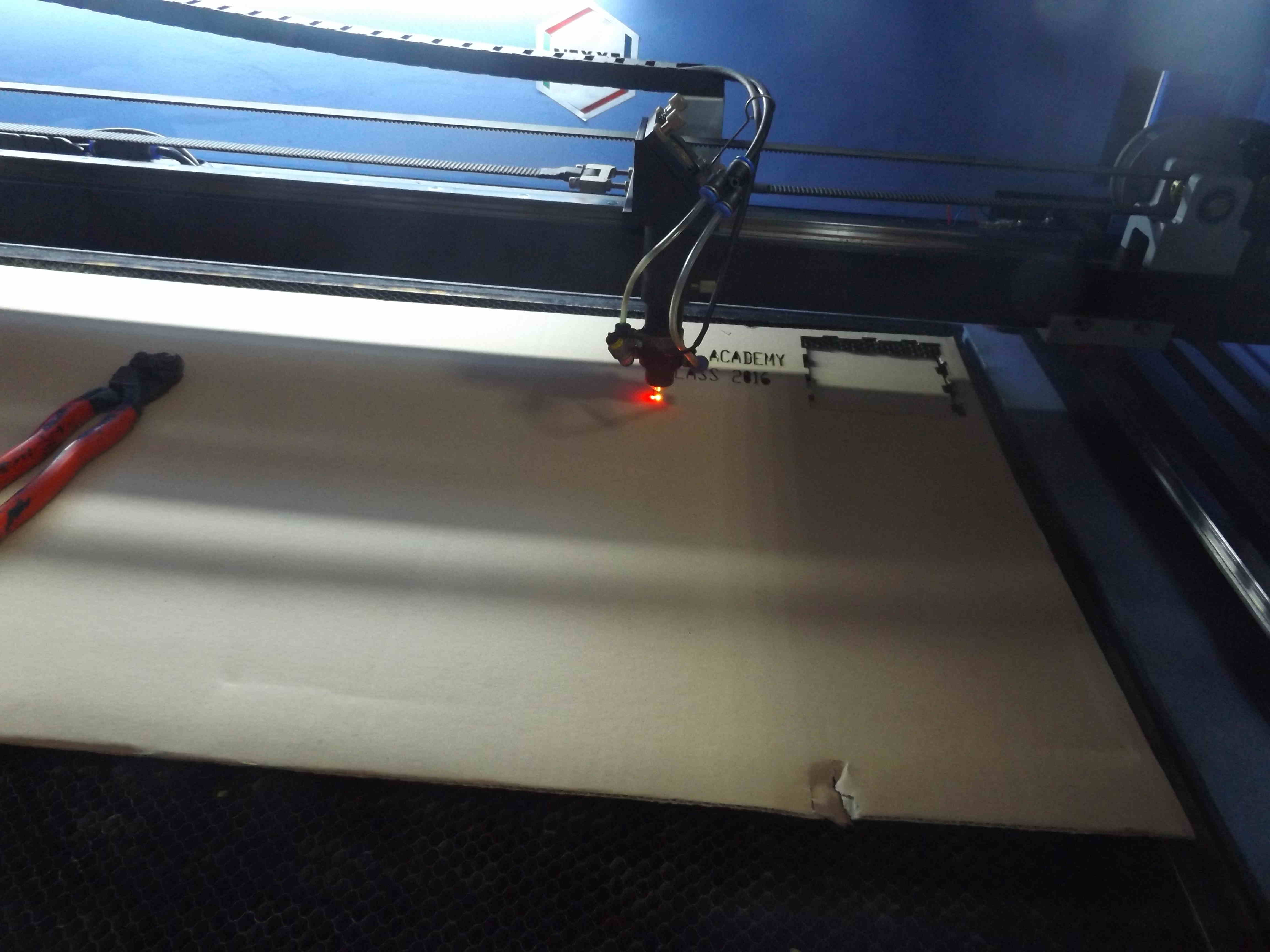
Laser cutter
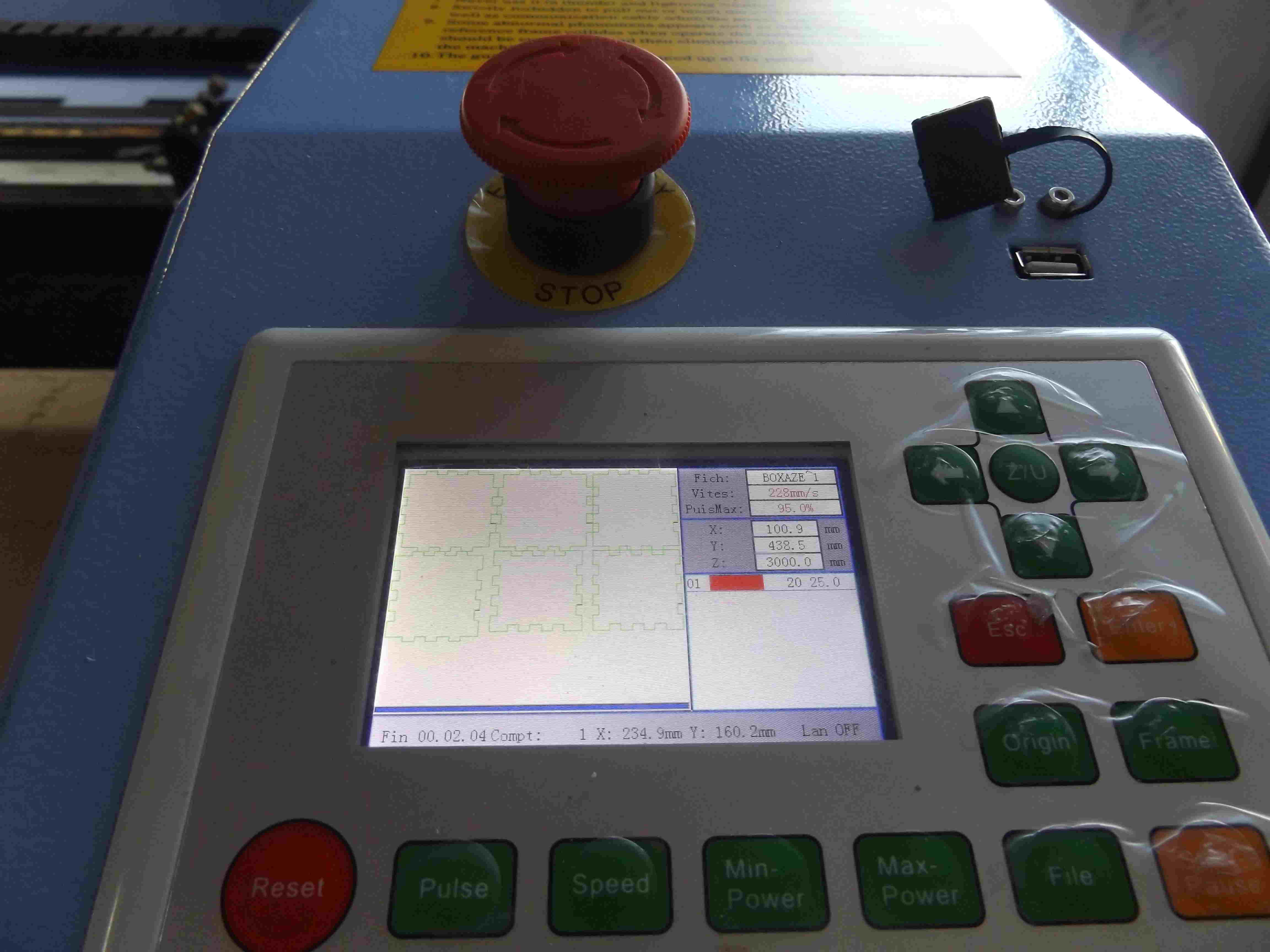
To send the job to the machine, I follow these steps, I first turn the key to turn on the machine, load the material I used cardboard sheet, I put something on the top to help fixing it, I choose my origin point with arrows, I insert the usb key, in the screen I choose file usb, click enter, read file from usb, then enter, choose the filename with arrow top and down, then send to memory, then esc twice, I choose the rd file from memory, click enter to confirm, then, click origin to send the starting point forcut process, click frame will show the area to be cutted in the material, click pause to send the job. see below some images taken during testing and cutting processes.
here you can dowload the file on dxf format
here you can dowload the file on svg format
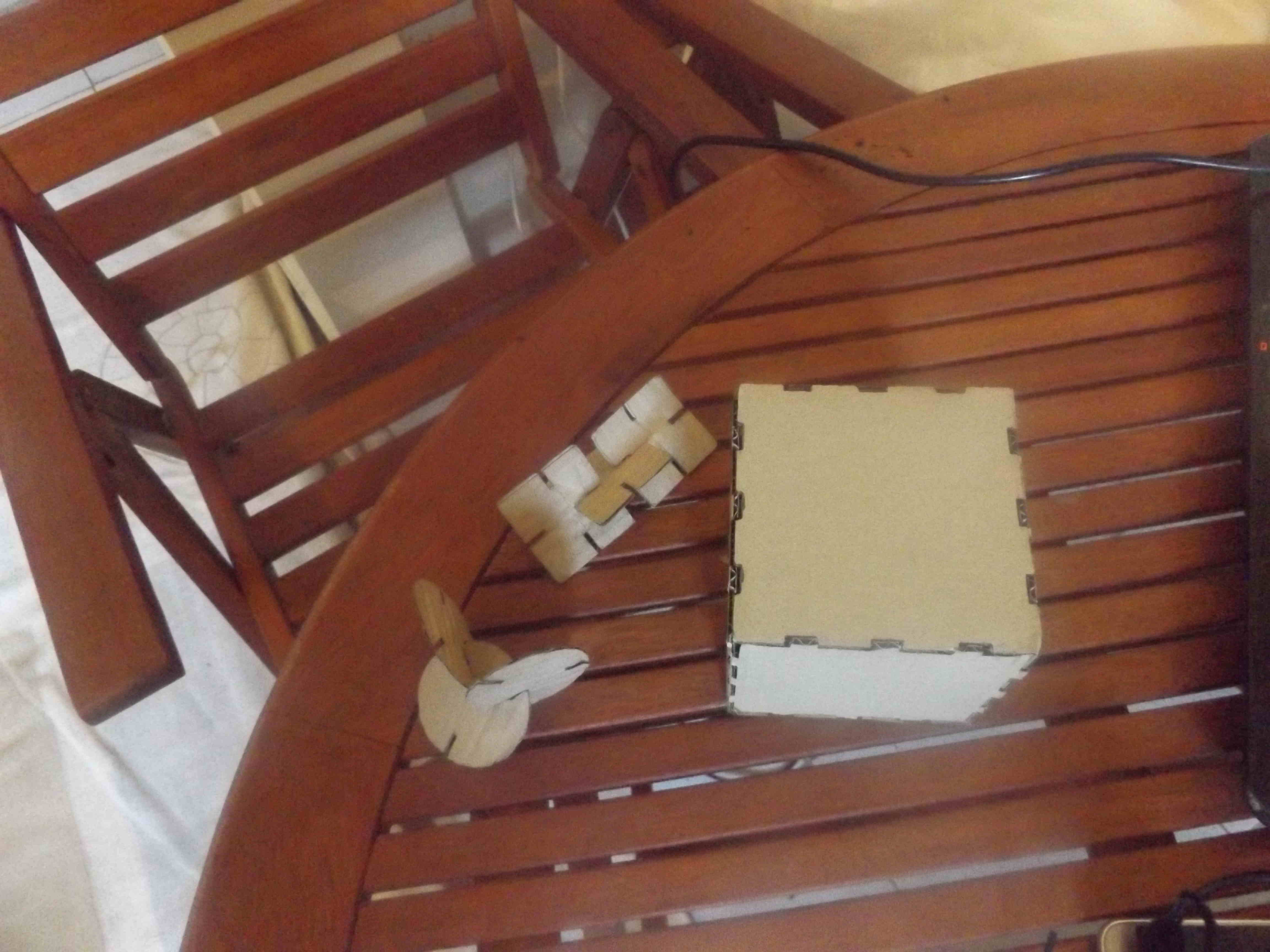
here is the results, this is from previous configuration but the last one is more correct because I consider the size when importing and exporting in dxf foramt in all programs
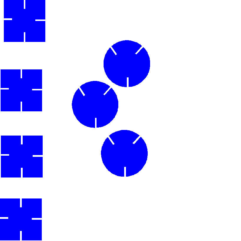
joints
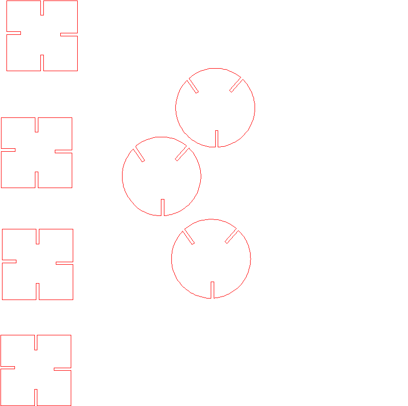
in this part I explain how to make joints with cardboard of 2.5 depth and kerf of 0.5mm, here Im drawing box of 50X50mm and tabs of 15X2mm, and cirles of 56mm in diameter
for boxes to palce the tabs, I clone four tabs and add at the center of each edge with alignement horizenatly/vertically and to the center according to the bieg object, for the circle I rotate the tab mirror and place them in the top left/right and align horizenaty then I place one in the botton in the center, I cloned four times the rectangle and the cirle, I detach the clone the apply path difference of all tabs here is the final result
to prepare for laser cutter I apply stroke of 0.5mm of weight: color red: and no background, I used the same laser cutter configuration of the previous chapter notice that speed can be higher than 7 here is the screenshots
here you can dowload the file on dxf format
here you can dowload the file on svg format
Laser cutter
Vinyl cutter
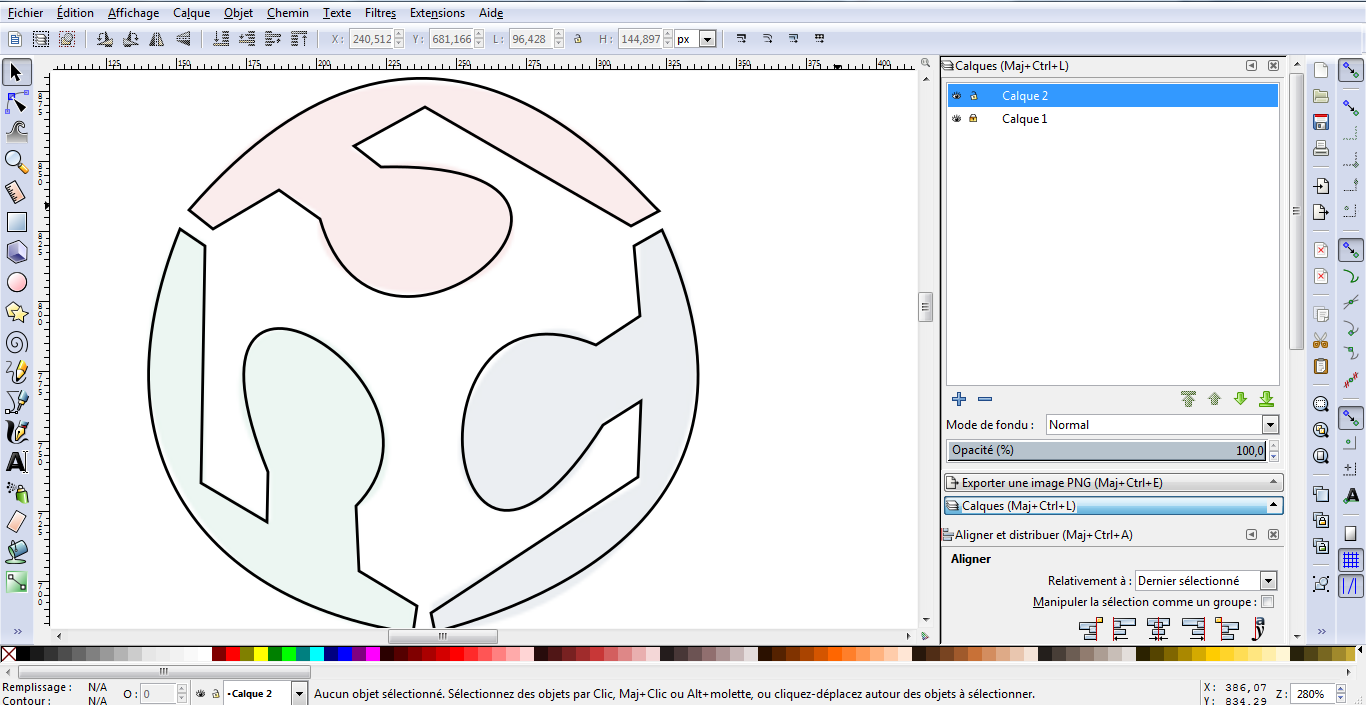
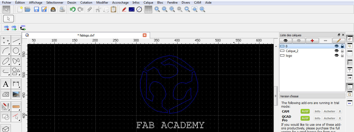
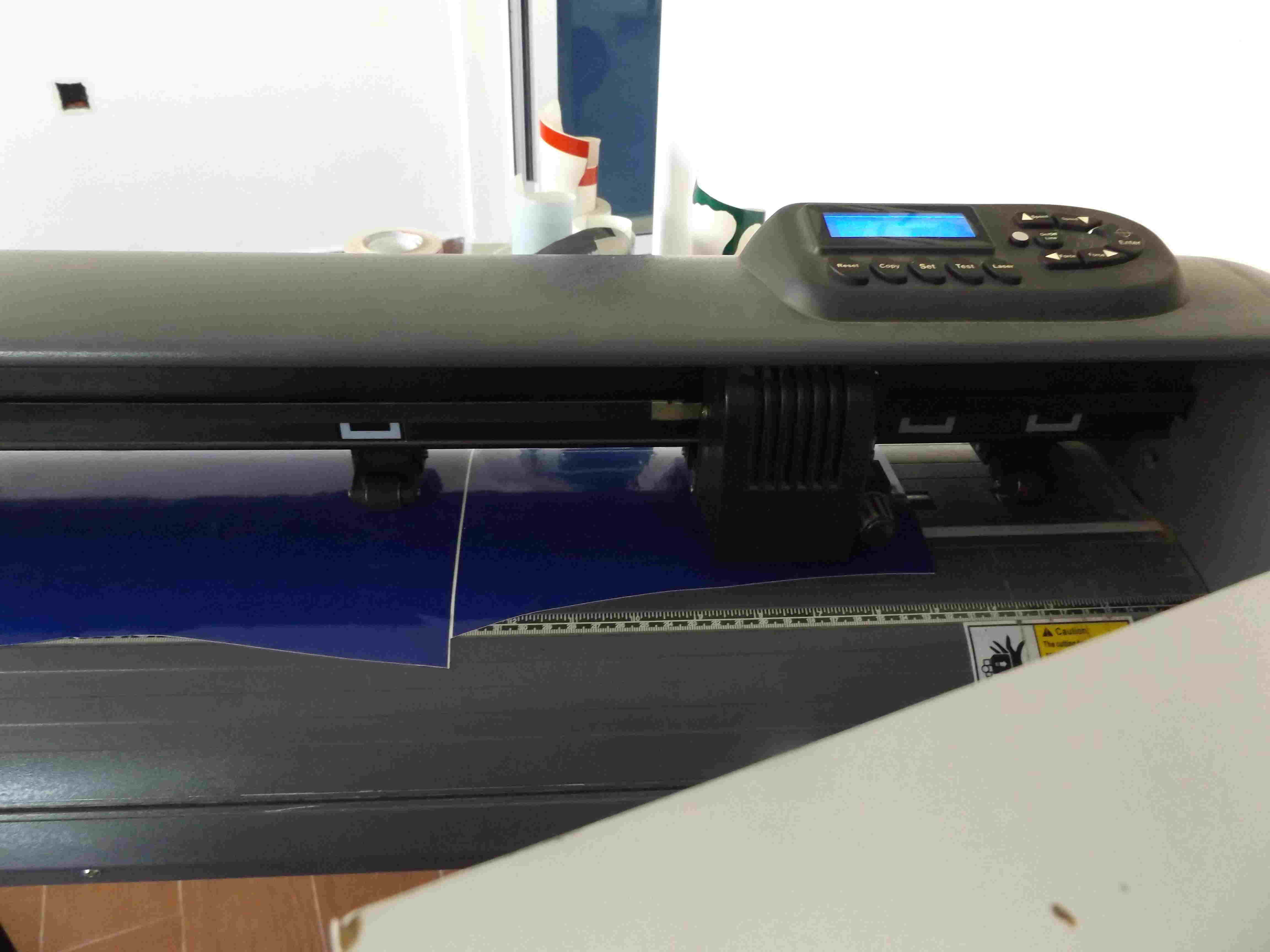
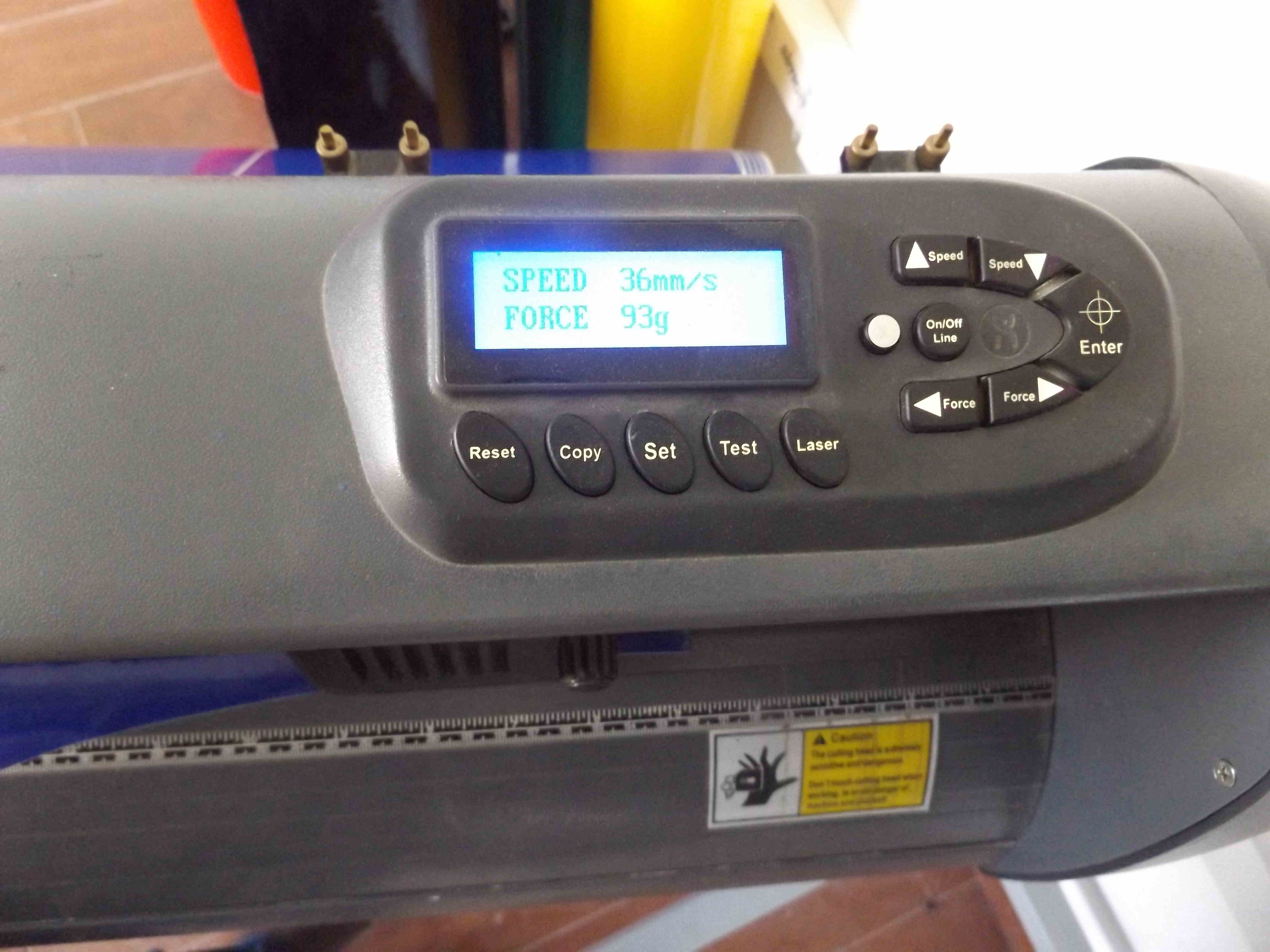
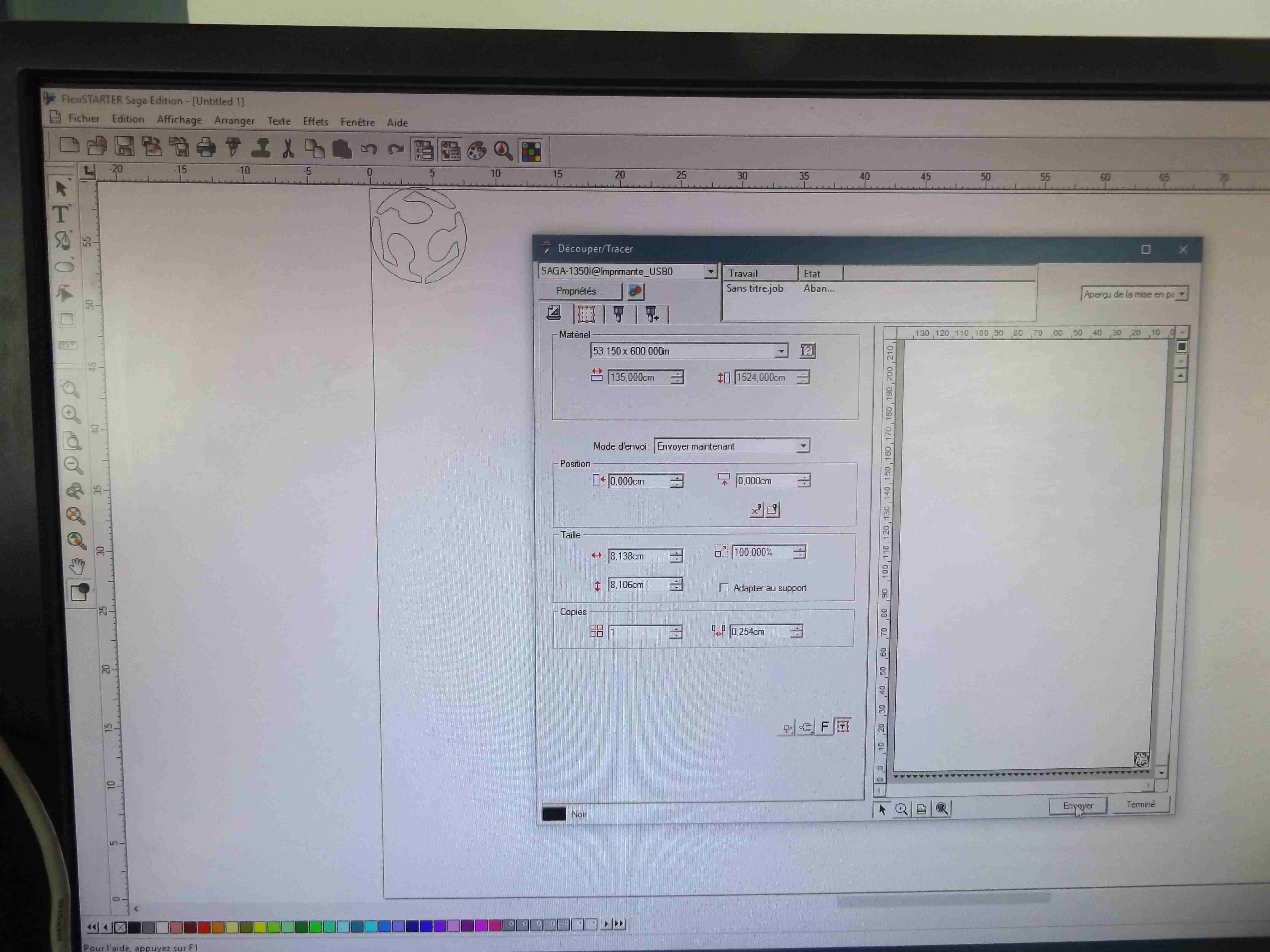
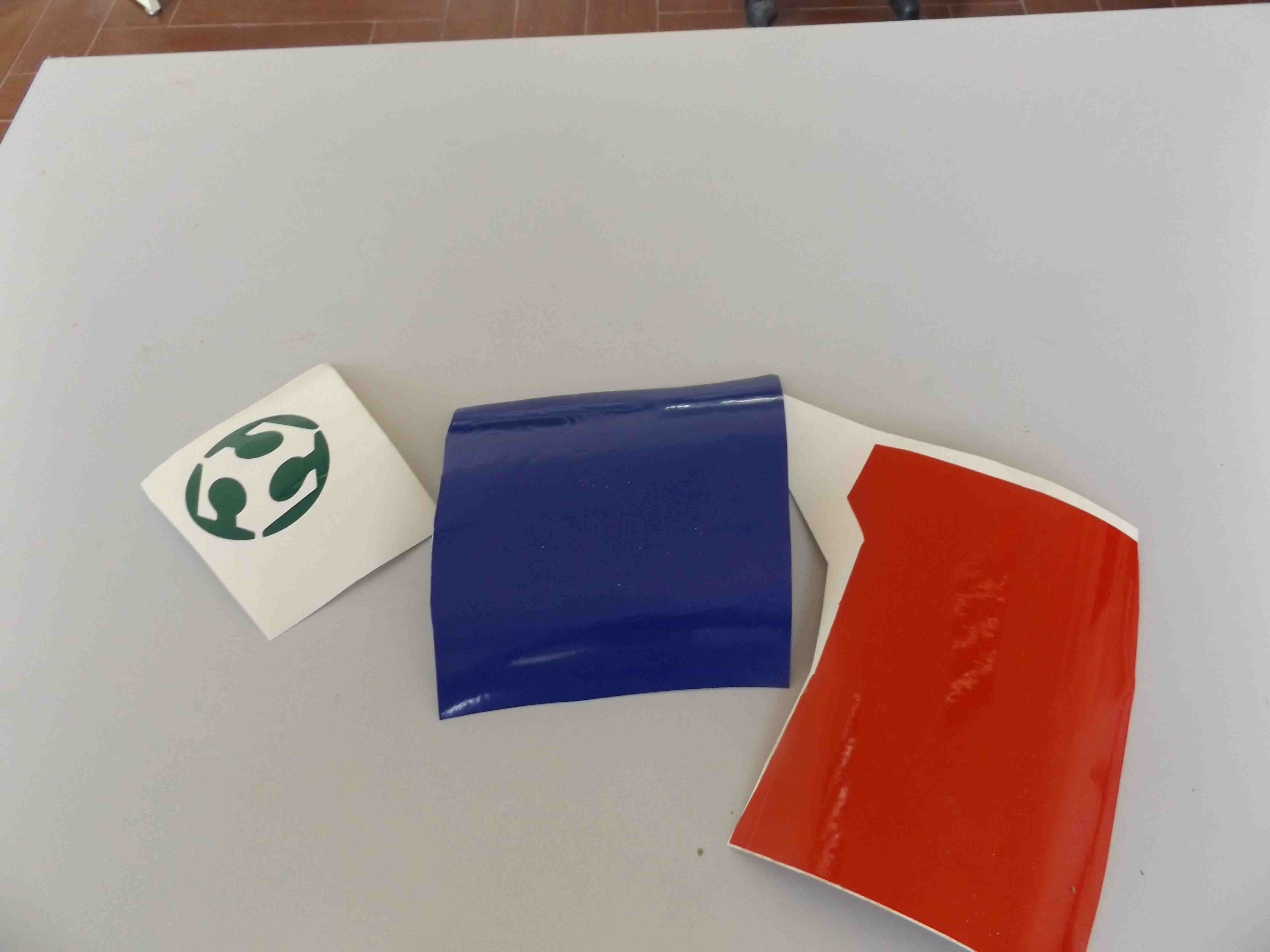
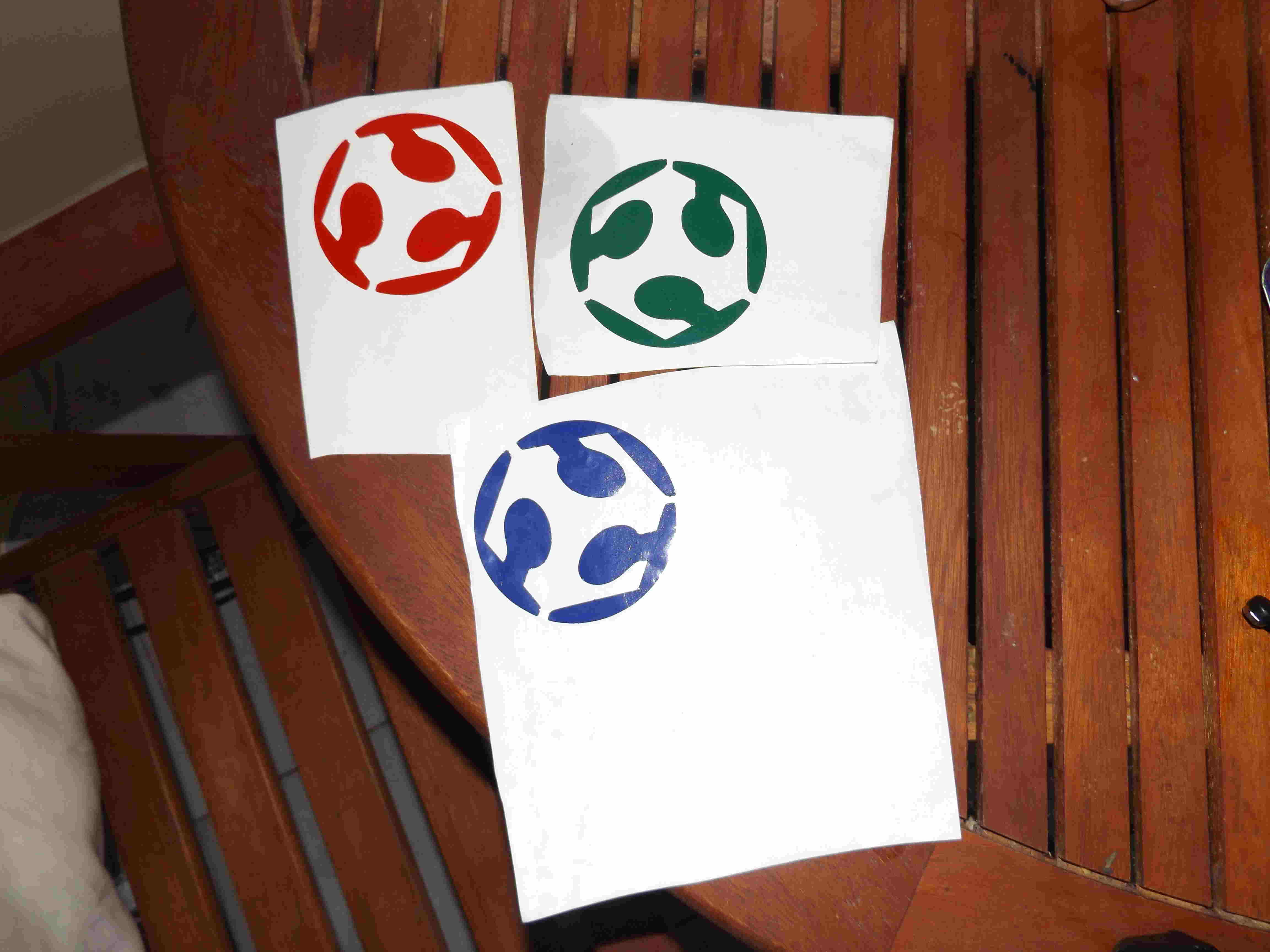
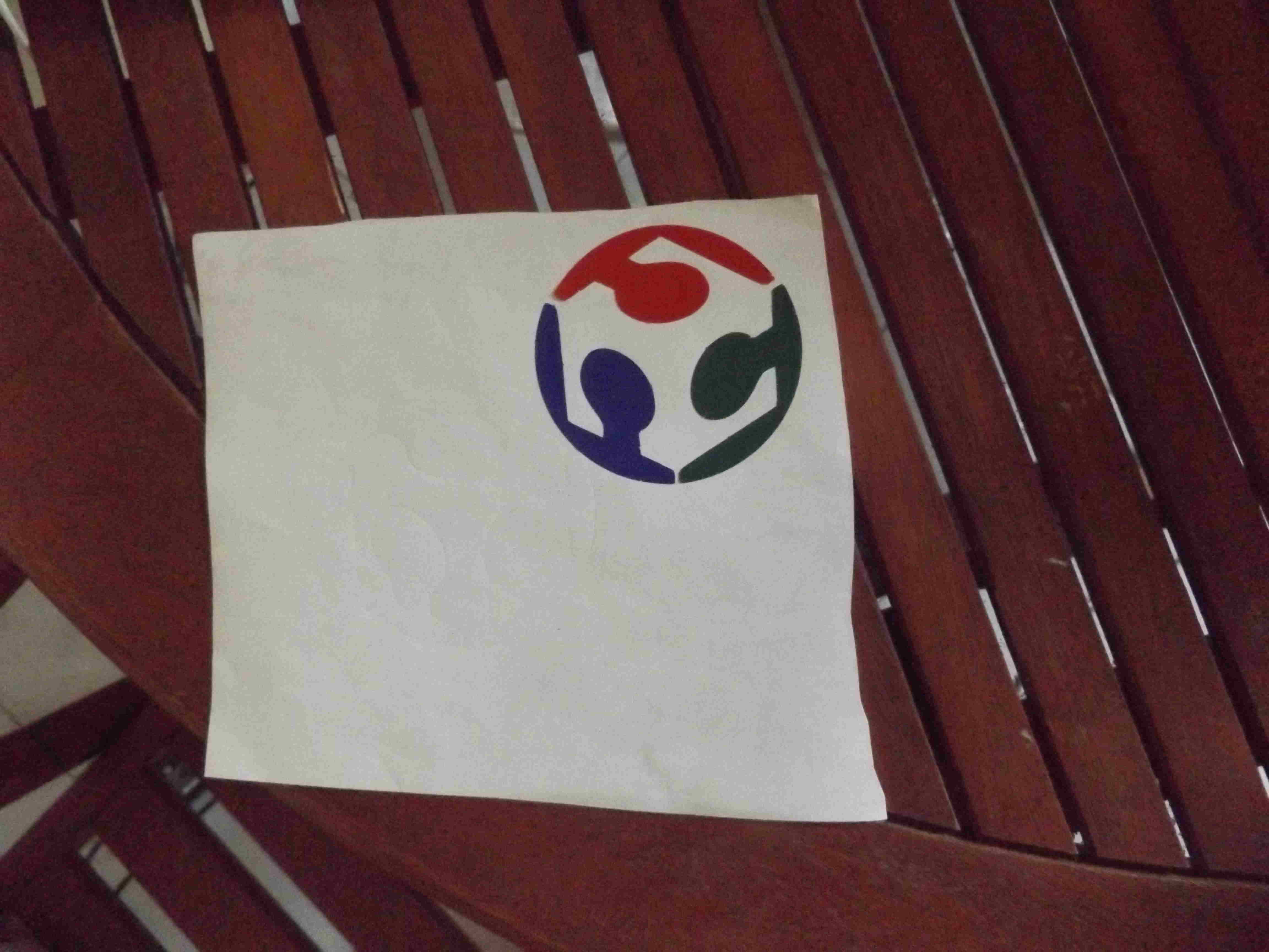
for this exercice I reproduce the fablab logo. I download the logo from the internet as an image in the first layer I decresase its opacity and add a second layer in witch I trace the border of the image with tracer curve tool I close the curve. in path menu I select and click on object to path I activate selection of all nodes then I select the nodes in the path and apply smooth , I select the object then apply group, in fill and stroke I adjust the stroke paint 0.5 px. I export the file in DXF format. when exporting from insckape I found it necessary to uncheck the options utilize ROBO Master in output,and LWPOLYLINE otherwise it may not be exported properly, then I import the file in dxf format into Qcad to check for double lines if there are any double lines I just select the segment and delete it I repeat for the three different paths, I print the logo on three vinyl red green blue, I place down the lever and load the blue vinyl roll on the roller behind the machine, make sure that the vinyl is loaded properly then pull up the lever, I turn on the vinyl select the roll, I use arrow keys to set the origin, click origin , I then import the dxf file into flexistarter saga the program to run the machine. in the tracer there is the size of the material and the object to cut, speed and power of cutting are 36mm/s and 93g as shown on the machine. then I send the job to the machine, after cutting the logo I unload the vinyl from the machine and cut the output file, I repeat for red and green rolls, below are the screenshots of the session.
 I didnt document my test here please check the laser cutting test on acrylic in final project page.
 to prepare for laser cutter I apply stroke of 0.5mm of weight: color red: and no background, I used the same laser cutter configuration of the previous chapter notice that speed can be higher than 7 here is the screenshots