The aims for this week were to:
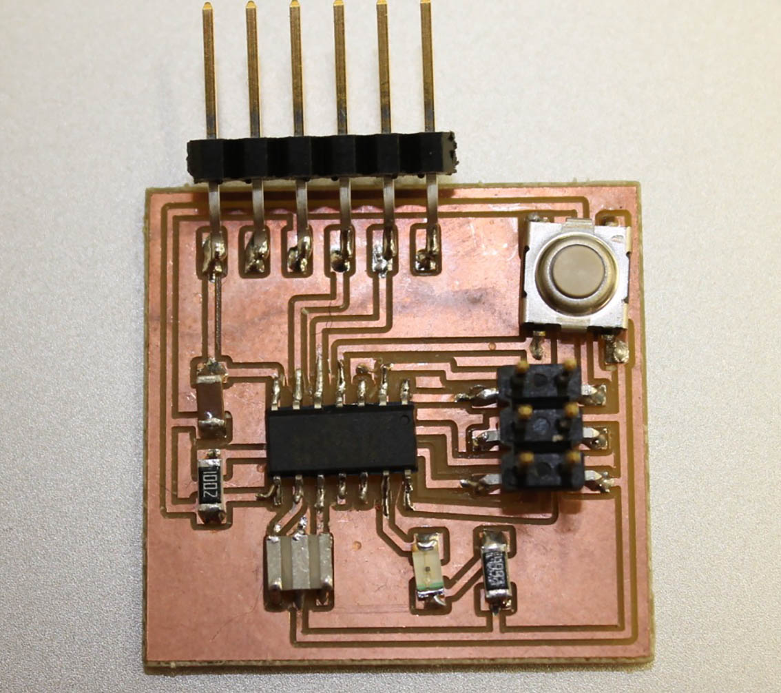
1. Redraw the echo hello-world board and add at least a button and LED with current-limiting resistor or design my own.
My tasks were to:
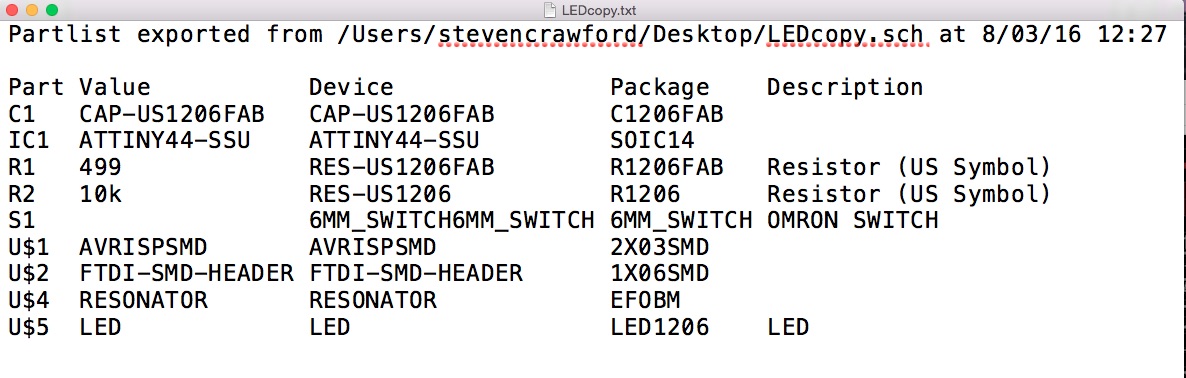
1. Draw a schematic 2. Place components on it from an imported library here 3. Route it 4. Simulate it 5. Fabricate it First I got familiar with the various components.There are millions of them but for now I'm concerned with the ones at the Fablab. A good book to buy about all of this is called 'The Art of Electronics' by Horowitz and Hill here.
We use 1206 standard packages at Fablab. A resistor is a passive two-terminal electrical component that implements electrical resistance as a circuit element here.
A capacitor (originally known as a condenser) is a passive two-terminal electrical component used to store electrical energy temporarily in an electric field. here.
A crystal is used to tell time. It is a capacitor with piezoelectricity which means electricity resulting from pressure. here. It oscillates. here.
A resonator is a device or system that exhibits resonance or resonant behavior, that is, it naturally oscillates at some frequencies, called its resonant frequencies, with greater amplitude than at others. The oscillations in a resonator can be either electromagnetic or mechanical (including acoustic). Resonators are used to either generate waves of specific frequencies or to select specific frequencies from a signal. here. Resonators have much lower tolerance and are cheaper. They have a capacitor built into them.
An inductor, also called a coil or reactor, is a passive two-terminal electrical component which resists changes in electric current passing through it.These are used for wearable technology, eg. conductive ink and thread. here.
This is the microcontroller we use in the Fablab. We call it the spider.The high-performance Atmel picoPower 8-bit AVR RISC-based microcontroller combines 4KB ISP flash memory, 256-Byte EEPROM, 256B SRAM, 12 general purpose I/O lines, 32 general purpose working registers, an 8-bit timer/counter with two PWM channels, a 16-bit timer/counter with two PWM channels, internal and external interrupts, an 8-channel 10-bit A/D converter, programmable gain stage (1x, 20x) for 12 differential ADC channel pairs, programmable watchdog timer with internal oscillator, internal calibrated oscillator, and four software selectable power saving modes. The device operates between 1.8-5.5 volts. By executing powerful instructions in a single clock cycle, the device achieves throughputs approaching 1 MIPS per MHz, balancing power consumption and processing speed. here.
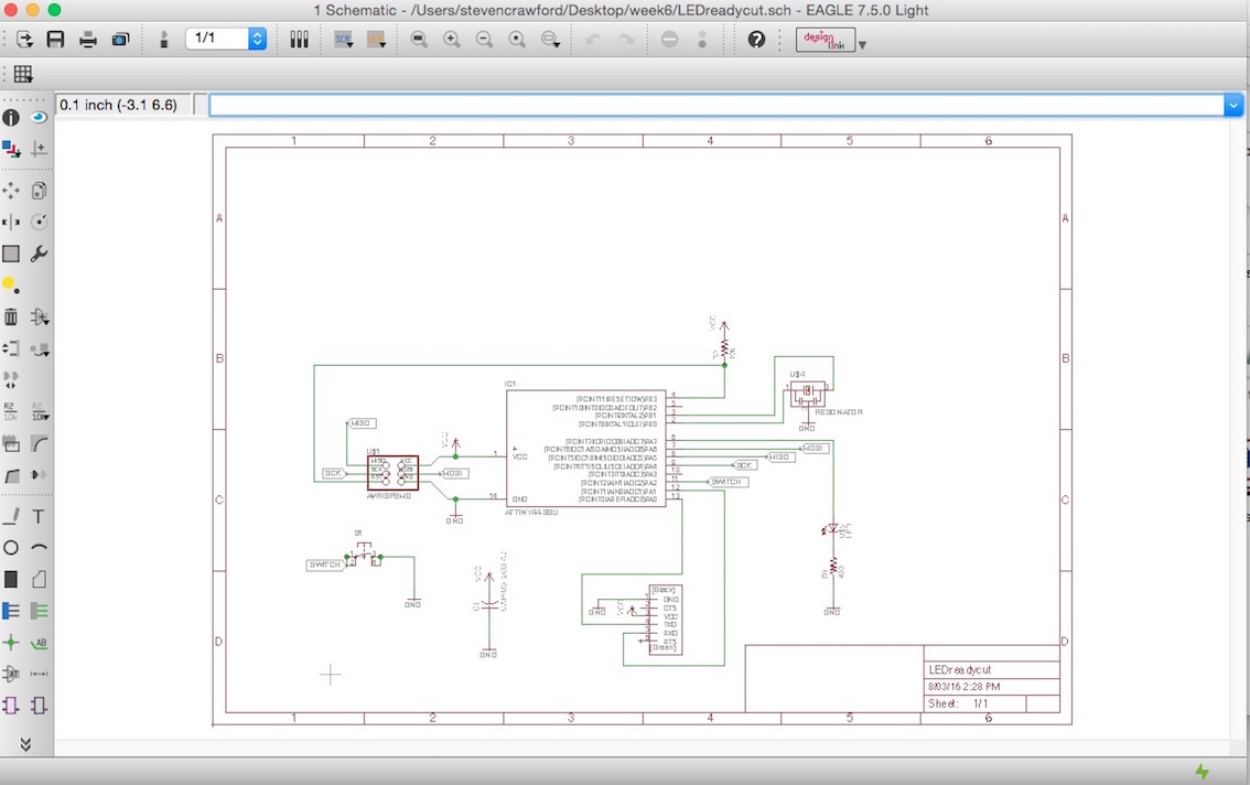
I spent many hours trying to redesign the echo board. In the end I realised just how difficult it is to reconcile these small electronic boards. My first attempts failed in some respects, but I did learn how to use Eagle reasonably well.Eagle is a software programme used to design the circuit board here. I now have a much better understanding about electronics. I am able to make better sense of schematics.
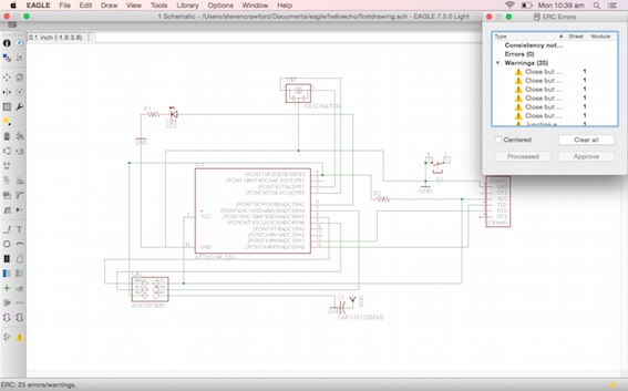
The schematics are found in the Fab Academy electronics libraries. They are no different to any other engineering drawings, humans still have to interpret them. When they are tidy and easy to read that reduces the chance of human error. The software does use the schematic, but not entirely - it still needs a lot of human input to make it work. Eagle is a very useful tool, but it doesn't provide a quick solution to board layout which is labour intensive.It thinks the frame, title and date on the schematic page is an elecronic component, for instance.
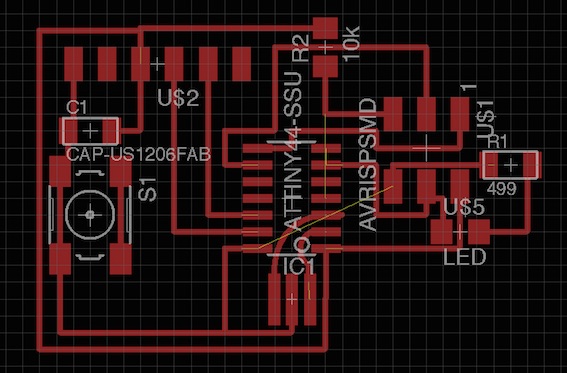
There were many overlaps and insufficient gaps between wires to sort out, after I ran the design rule check (DRC). With some guidance from my Fablab people I worked my way through the highlighted problems, mainly overlaps and narrow gaps between wires. Then presto, a fully resolved project ready to be made into a trace.
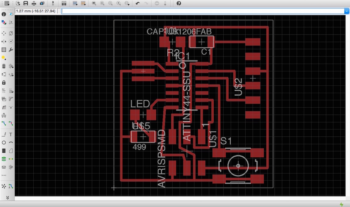
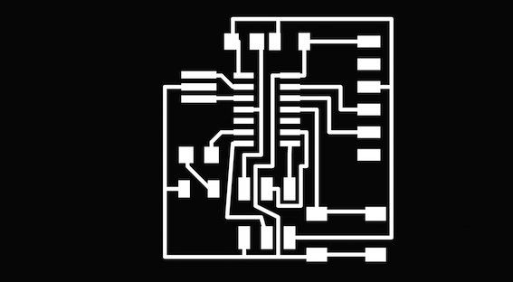
I exported the design in monochrome with the resolution set to high, 2000 dpi. This gives it the strong contrast required by the fabmodules to find the cutting line. Fabmodules use the contrasting bitmaps for its cutting paths.