
Electronics Production
The assignment for this week is to make a fabisp using the designs and hex code which are made already. We are using Rolland Modella MDX 20 to mill the pcb, which is a 2.5D mcahine and can also be used for milling wax with limited depth (Z axis).
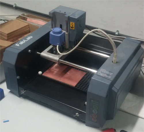
Modella MDX 20
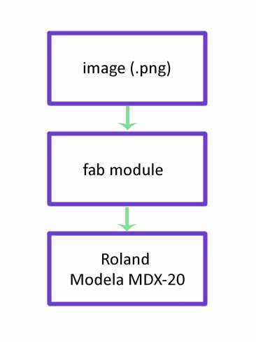
The steps for milling a pcb are desiging the circuit (export as .png format), using the fab modules to controll the machine, setting the machine and milling.
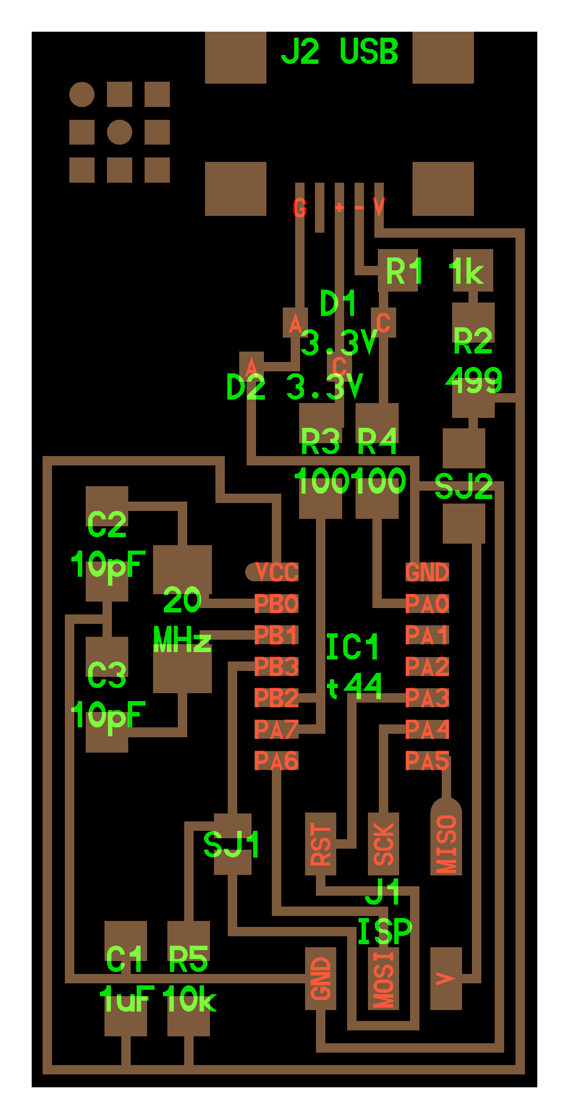
This is the first part, the design. If you are using the fab modules , the the design should be in .png format. We took the design from http://fab.cba.mit.edu/content/projects/fabisp which is already done using the Eagle software. The schematic file is in eagle is also available in the site.
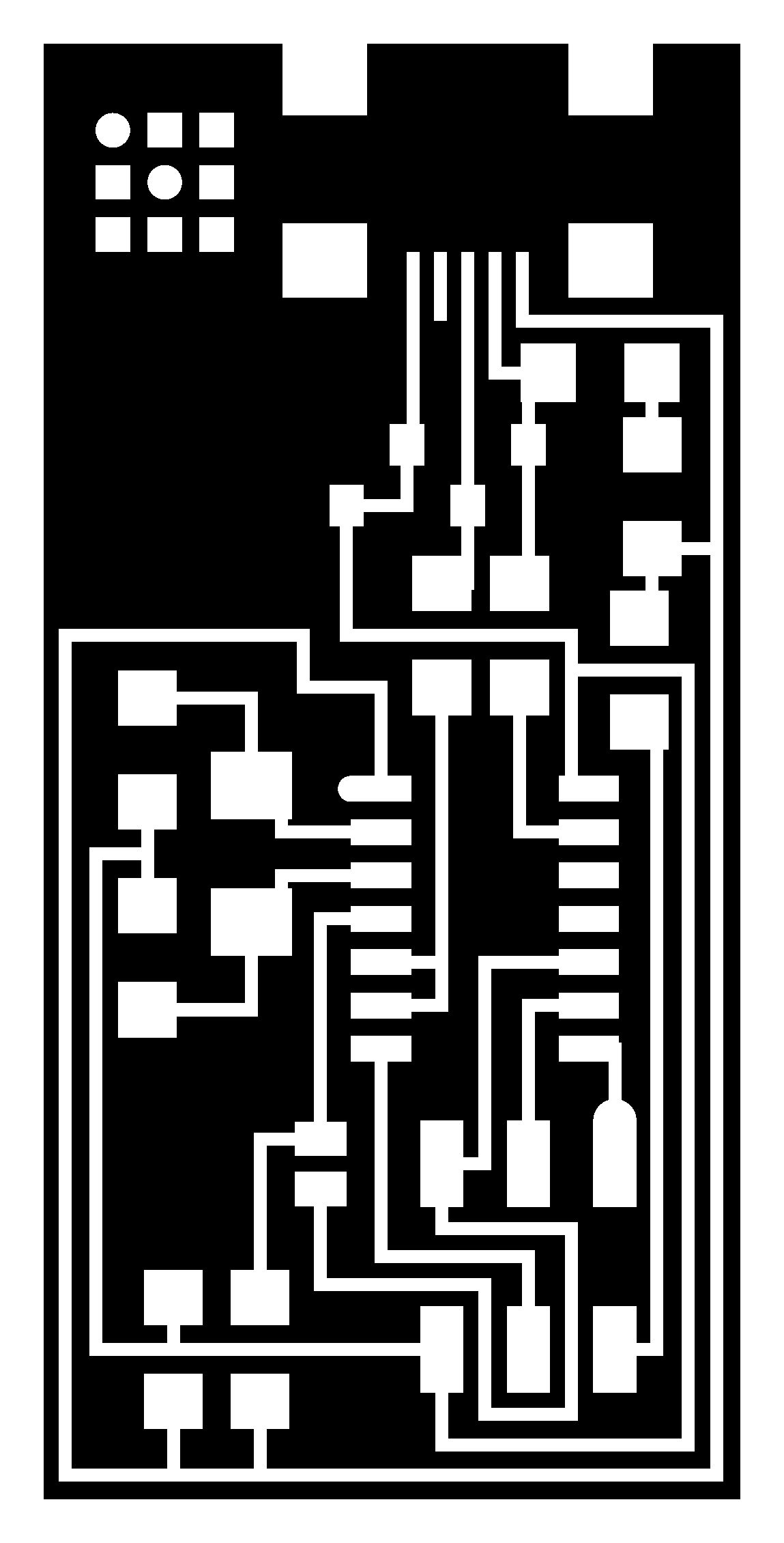
What happens when milling a pcb is, removing the unwanted coper parts in the coper board , keeping the traces where the components are to be placed. So in the picture above the white color is the traces and the black is the portions to be removed. The fab modules reads the png file and detect the postions of the black color and commands the machine to mill that position. Once you mill the board it should be cut from the parent coper board. So we need another png file for this operation. That png file contains only the outline of the board.

This is the cut out file
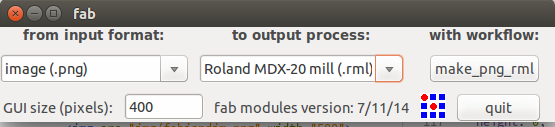
Using fab module is same as we did for the vinyl cutter. Open the terminal and type "fab"
A window will pop up. Select the following
input format : Image(.png)
output process : Rolland MDX20
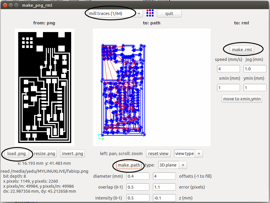
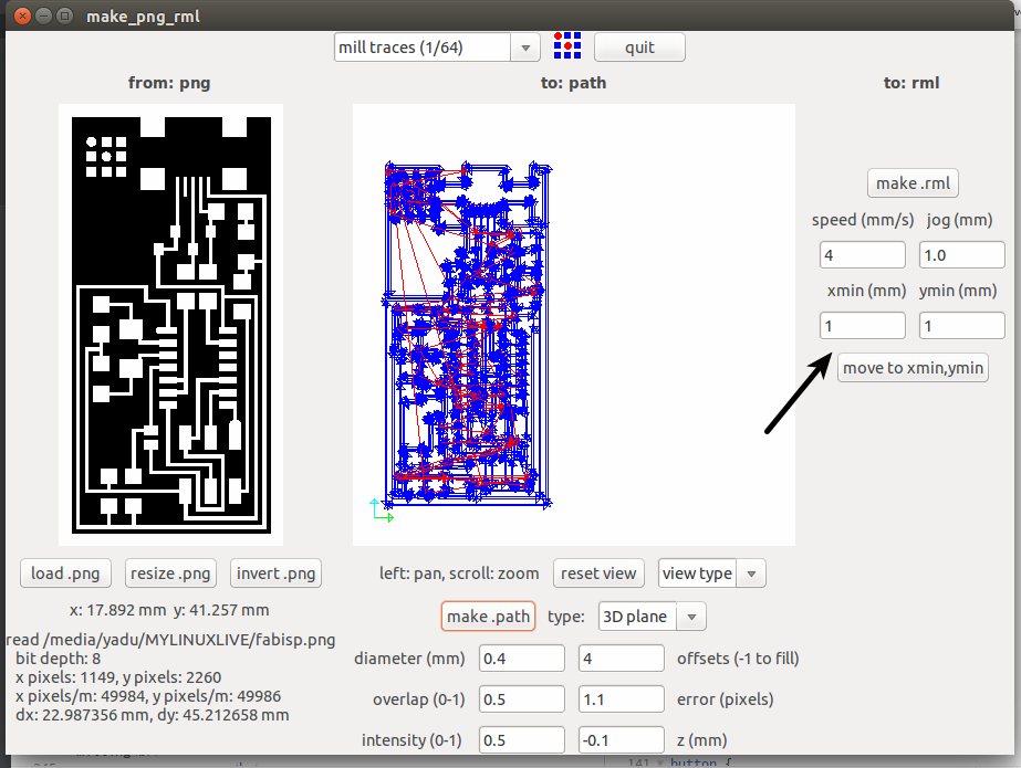
Now click "make_png_rml"
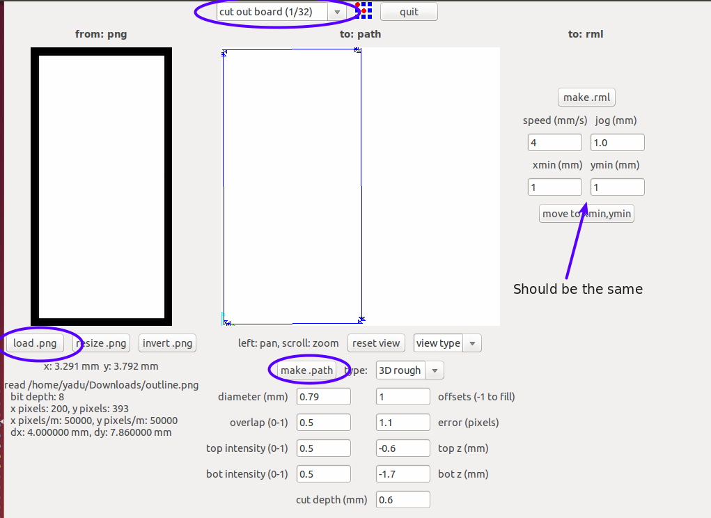
Now another window will come. Load the image (our design which is in the png format). Then click on make path button. Choose the process as "mill traces(1/64)" on the top of the window. And the final step is to click on "make .rml" button and then on "send it!" button
Before clicking the "make .rml" we need to set up the machine.
Now we have to set up the machine, like selecting bits, placing coper board, setting the origin etc.
Here we use two types of bitts
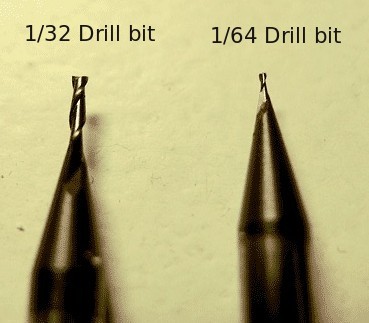
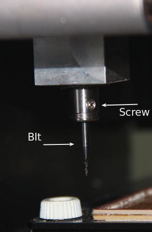
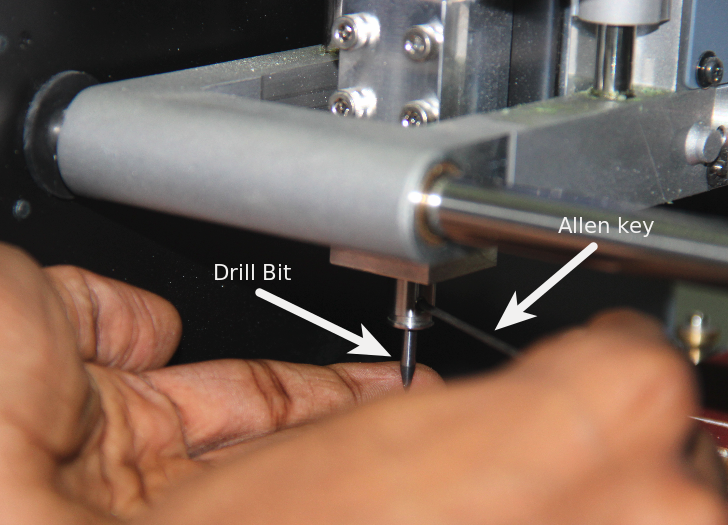
Here we use the 1/64 bit. For mounting the bit on the head, there is a screw that is to be loosen first. We can use allen key to loosen it. Then place the bit such that the majority of the bit goes inside the head. Then tighten the screw using the allen key
Next is placing the board. There is grid marked on the machine so that we can understand the position. The default origin of the machine is at left bottom. It is better to place the copper board at the left bottom side. Double sided tap can be used to fix the copper board.
Next we want to set the origin. The Bit tip should be at the origin point with respect to the copper board. So we have to move the bit tip to the point where we want to set it as the origin. For that we can use the "X min" and "Y min" options in the fab module. Giving x and y values and clicking on "go to x min y min" the tip will go to positions. We can move the tip to the correct position using trial and error method.
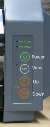
Once we set the x and y axes, next is to set the Z axis. The Z axis is to be set such that the tip of the bit just touches the copper board. For that there are two buttons - UP and DOWN- on the machine which will move the bit to up and down.
Once we set all the axes, then click on "make .rml" and then on " Send it". NOw the machine will start milling
For cutting the board , we have to do all these procedures once more with the cut out image and the 1/32 bit.
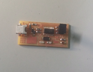
Now the pcb is ready and the next is soldering the components. For soldering, we use soldering station of Weller which is very nice to use.
I wrote down all the components required in a paper.I started soldering the components according to the circuit diagram.
Finally the hardware part of the ISP is ready.
The steps to program the isp is also explained in http://fab.cba.mit.edu/content/projects/fabisp For programming the isp, we need avr-gcc installed in Ubuntu. We can install it using terminal
sudo apt-get install gcc-avr binutils-avr gdb-avr avr-libc avrdude
    make clean
    make hex
#AVRDUDE = avrdude -c avrisp2 -P usb -p $(DEVICE)
Replace the "avrisp2" with the programmer we have in the fablab. Save the file and run the commands
        make fuse
        make program
But i faced a problem during programming
The steps and commands for programming in ubuntu is explained above. But the in the line