
Networking and Communications
The assignment for this week is to "design and build a wired and/or wireless network connecting at least two processors" So my plan is to make a wireless remote cntrol for the canon DSLR , which will be usefull for my project.
Wireless DSLR remote control
Components used
Above listed are the components for the remote control, I didnt add the Atmega328p in itm which will also be used. Since i already have a board with atmega 328p, I am not making another board with Atmega328p for this purpose.
The first things we have to know is about the camera. Here in Fablab we have a Canon DSLR. The camera has a 2.5mm socket fot connecting remote. I got many usefull datas this website
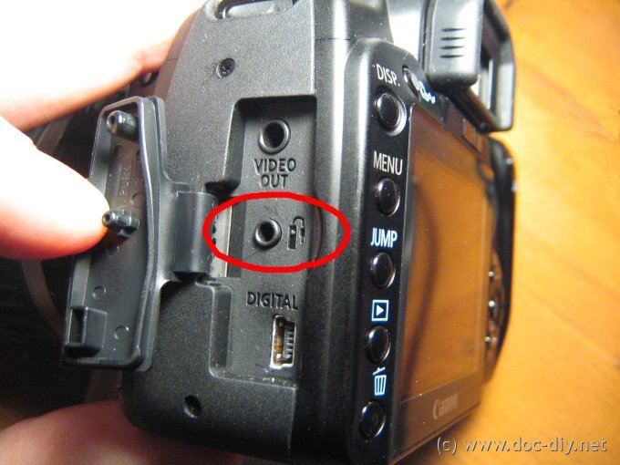

So when we short the two points shown in figur, camera will get trigered and it will take snape. So i desided to use mosfet to short the two points of 2.5mm jack. Since i ma using the mosfet i should know the direction of current flow or the ground point of the 2.5mm jack. Here the ground is the left most portion(according to the figure shown) of the jack.
So by connecting a mosfet as shown in the below figure , we can short the two pins by giving a puls to the gate of Mosfet
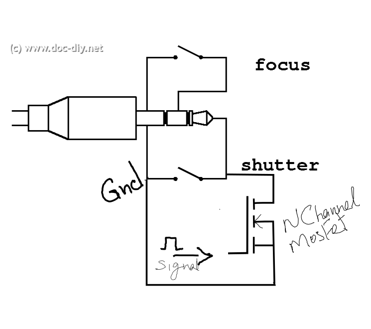
SO this is the basic diagram for trigering the camera. Now i have to design the controller board using ATtiny45 and XBee module.
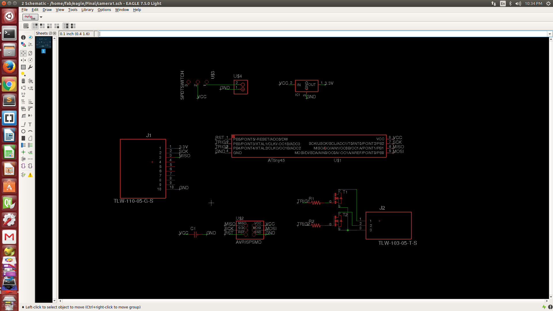
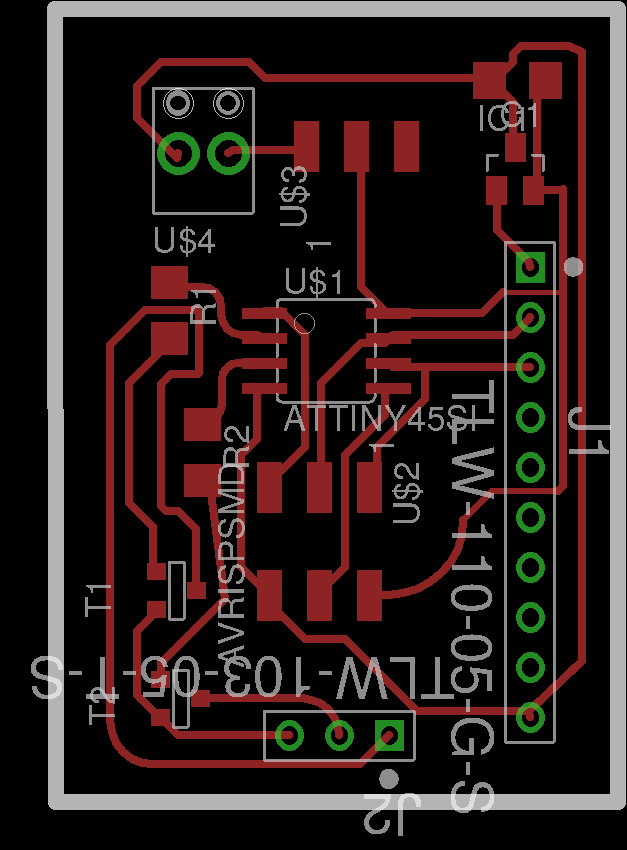
I milled the board and soldered the components.
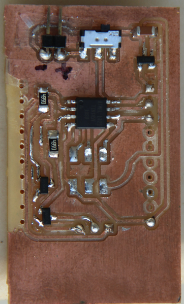
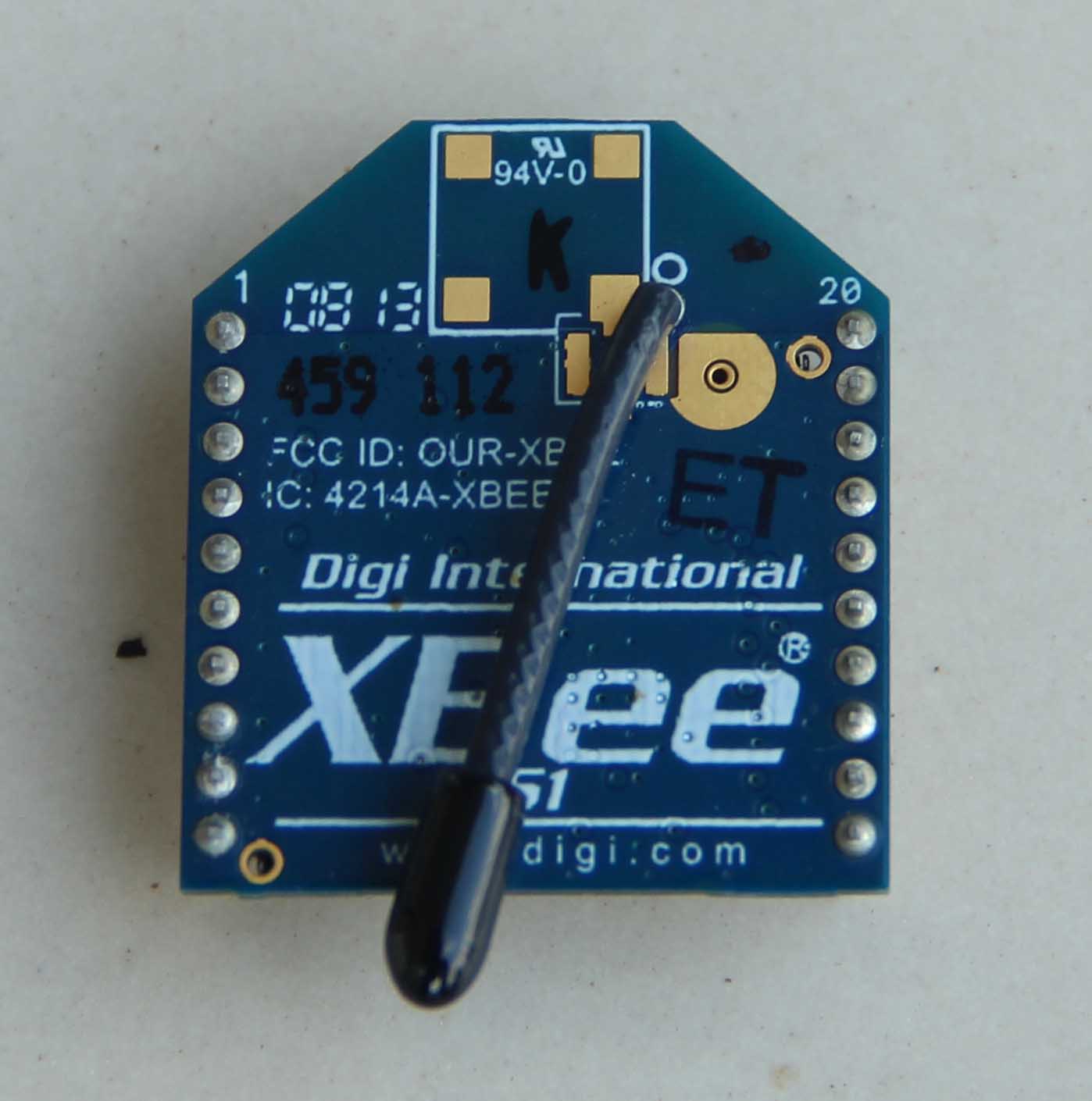
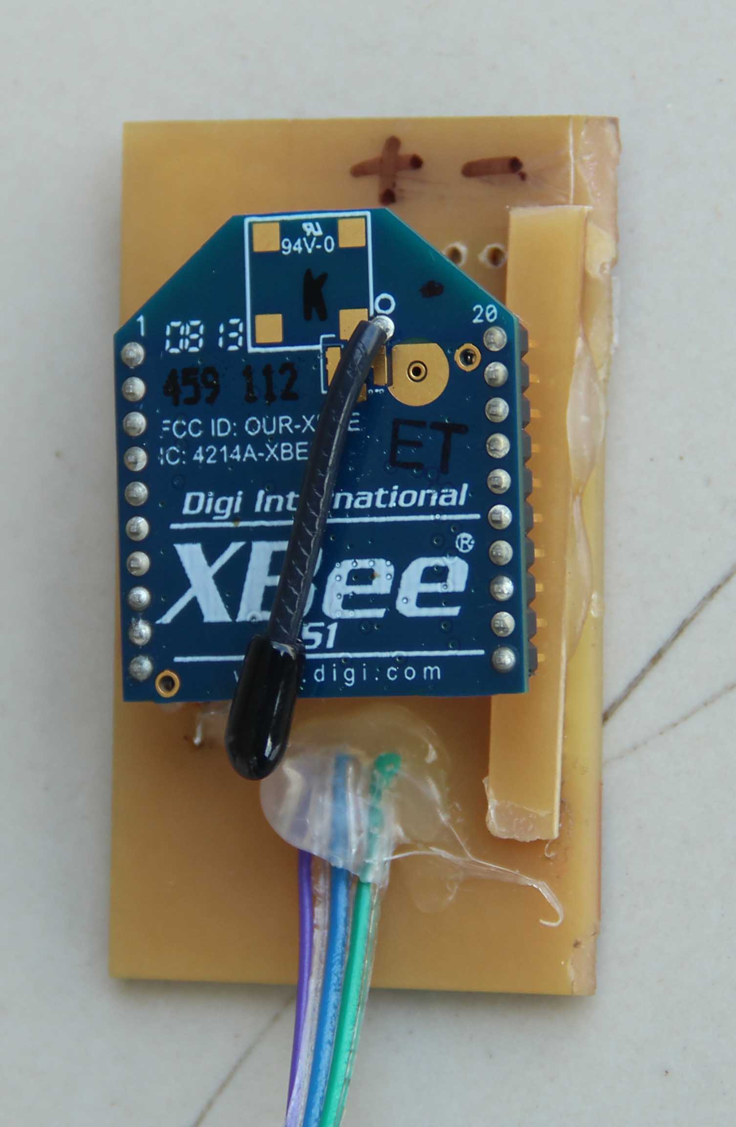
I have given some slotes to connect the xbee module. This is the XBee module
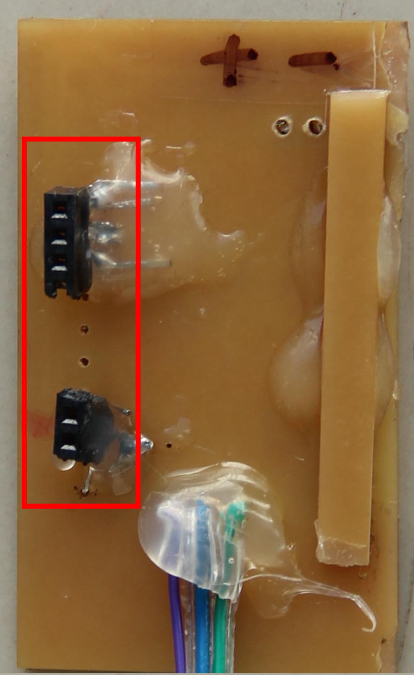
Here are the slots for Xbee module
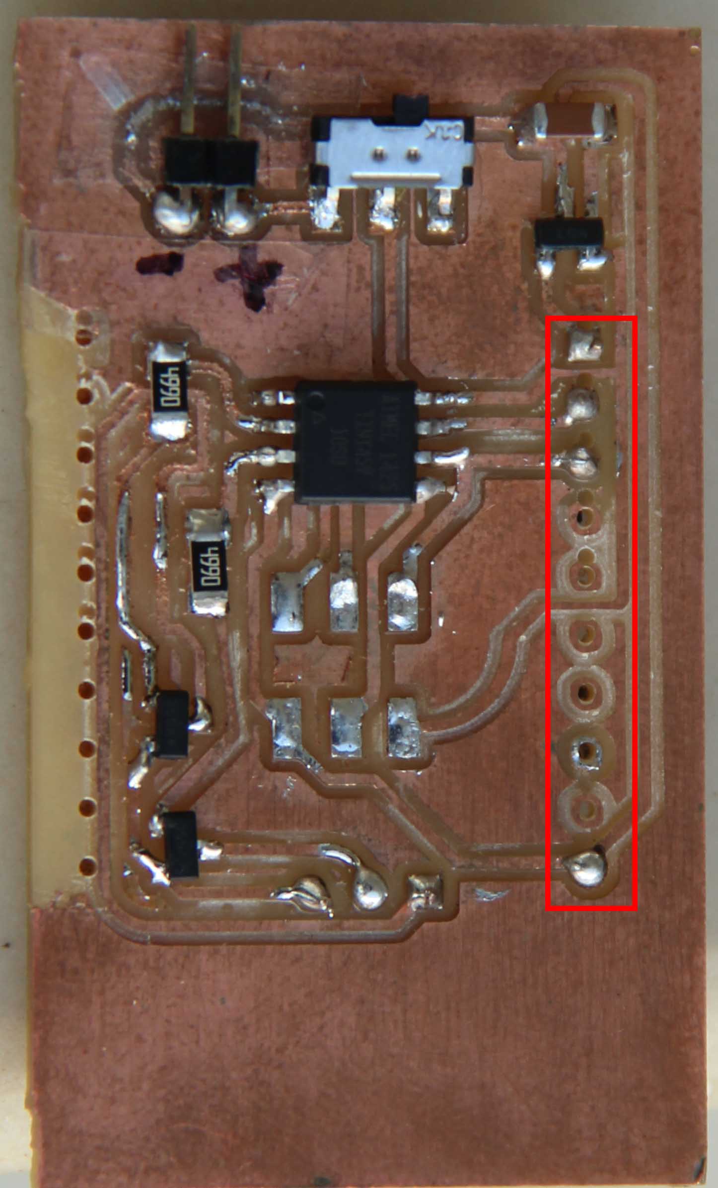
When I gave pulses to the gate of MosFet it was not getting trigered properly. But when i touches the board or the components soldered it will get trigered. So i thought it might be some loose contact or problem in soldering etc. But then i realised a mistake i did in this board. The mistake was the source of the MosFet and the ground pin of the micro controller was not connected!!! I missed it during desigining in eagle. So mannually connected in using a small wire.
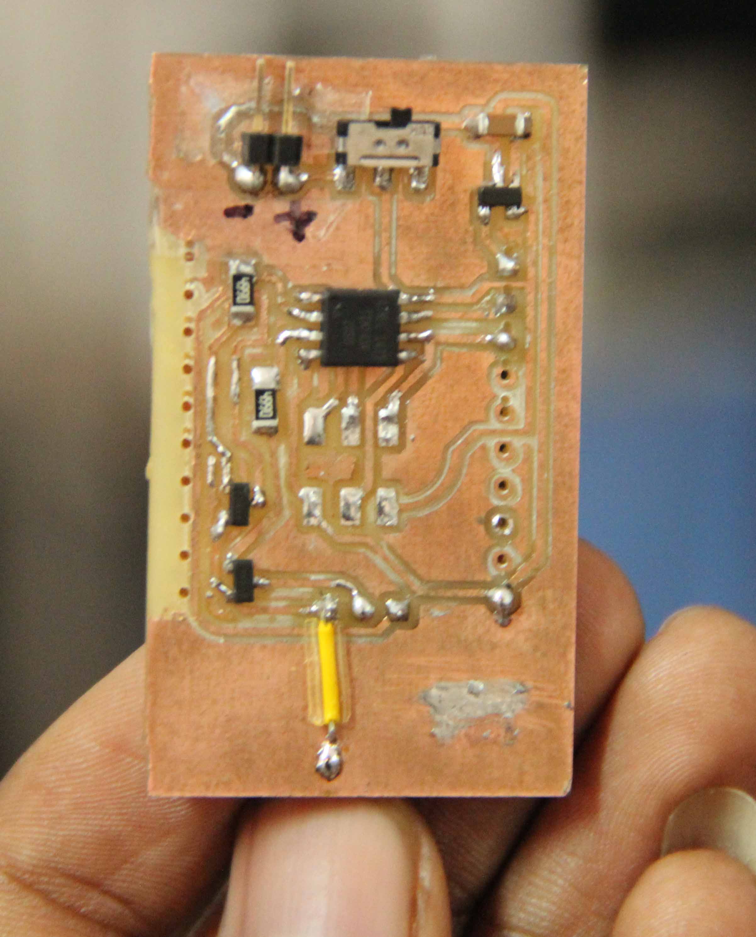
Now it is working properly! See the final board connected with battery

Next is the communication part.
My plan is to make a serial communication between them. Since ATtin45 doesn't have a UART register i have to use soft UART. Neil has already given some code for soft UART, so i have to edit it and use it.
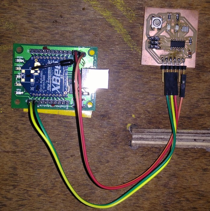
I assigned pins PB2 and PB1 as Tx and Rx of the Tiny45. The Rx and Tx of the xbee is connected tothe Tx and Rx of the Tiny45. When the Tiny45 recieves the charecter 's' it will triger the mosfet and camera will take snaps. This is my logic. So Atmega 328p will send a 's' via XBee. ATmega328 has an inbult UART register so i can use that Rx and Tx pins for connecting to XBee. But In my project i will be using a bluetooth module for communication between PC/ Mobile with the controller. So i will be using the Rx and Tx pins for that purpose. So i decided to use a soft UART in Atmgea328 for XBee communication. So now both the tiny 45 and atmega 328 have Soft UART for serial communication.The C files can be downloaded from below links. In Tiny45 the program is just to check whether the charector recieved is s and to triger camera. But in ATmega 328 i have written a program usefull for my project. When I send a charecter 't' to ATmgea328 via normal UART (inbuilt UART register) either using FTDI or bluetooth, atmega328 will send the charecter 's' to tiny45 over XBee. In my project i will be communicating with the controller board over bluetooth and controller board will communicate with the camera remote via Xbee. So this is what i tested.
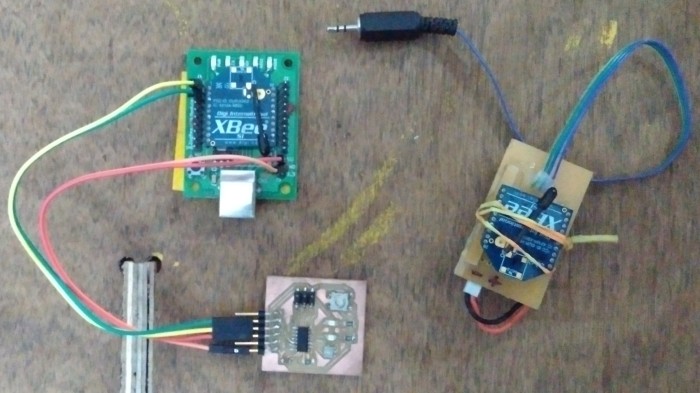
The aboove video shows the communication between atmega328 and Attiny45(remote). Then i tried using hello ftdi board which i made during the electronics design week to communicate with the camera remote.
See the hello ftdi board connected with Xbee
Downloads
Board_mill
Camera_t45.c , Atmega328.c , tiny44.c