
Output Devices
Assignment
Add an output device to a microcontroller board you've designed and program it to do something Plan
There are many output devices listed here by Neil. My plan is to make a propeller display with LEDs. First I should say what is a propeller display. Propeller display is a electronic model with some LEDs aranged in a linear shape on a PCB. This PCB will be mounted on shaft and rotated using a motor. By adjusting the on-off time of the LED we can make any design, word or any visual though there is only on linear array of LED.
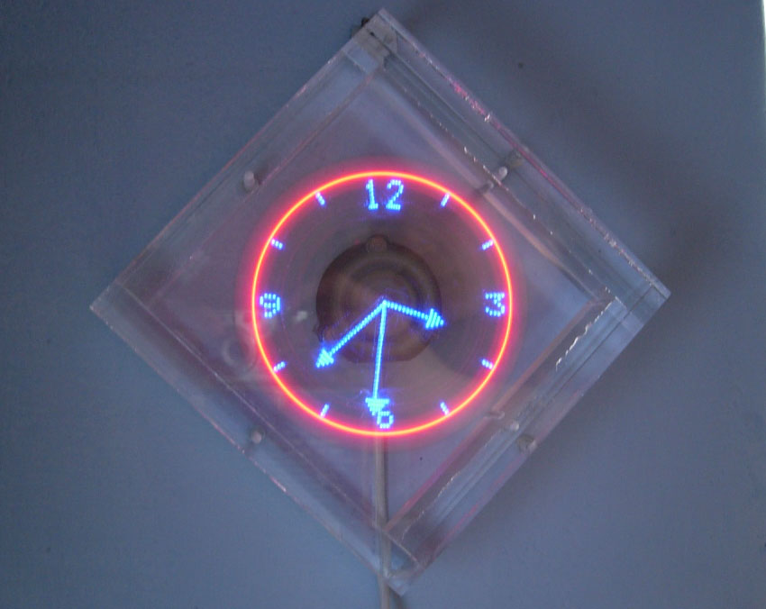
Here is an example for a propeller display I got when i googled.
Now i can show you the allgorithm begind a propeller display and how to wirte a letter using propeller display.
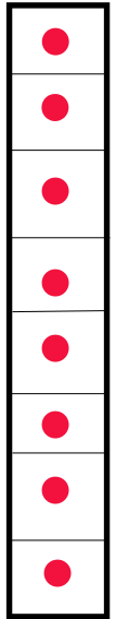
The image below ia linear array of LED. The array consists of 8 LEDs. Led is represented by red dots.
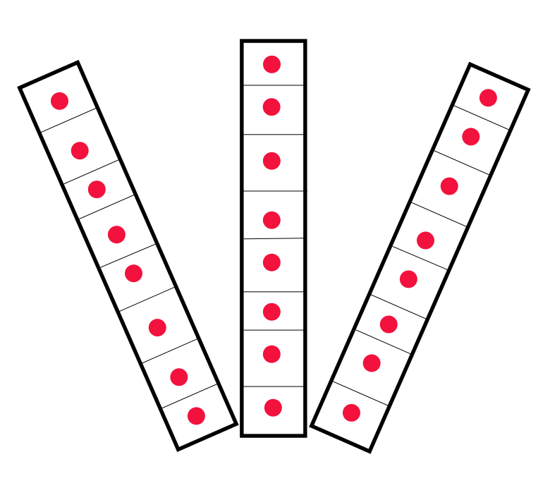
If the radius of rotation is much more, the array can be considered as a rectangular array.
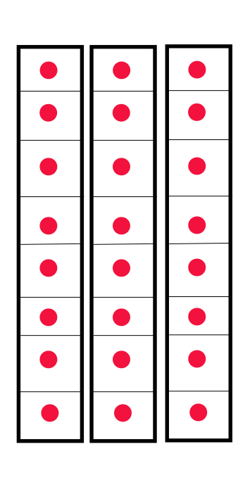
Finally we got rectangular array with the rotating LEDs. Now its simple to write a letter . For example if we want to wrire "A" it can be done as shown below.
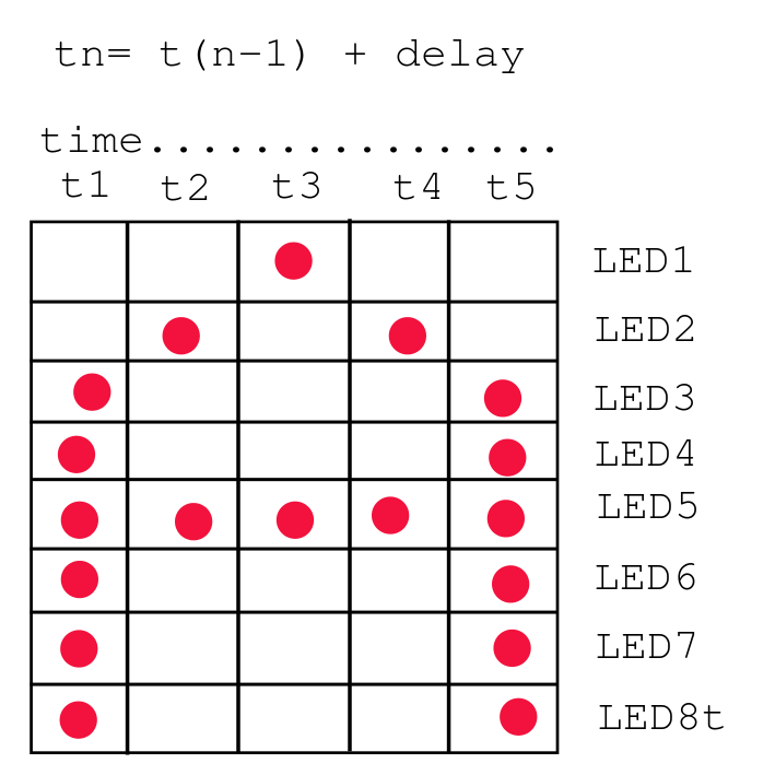
The most important part of this project is the tmie delay. The width of each strip is determined from the time delay. For how much time the LEDs are On and how much time the LEDs are off. Here in the casw of "A" LED 1 and LED2 are off and all others are on at time t1. It remains for a small interval (the delay). Then LED2 and 5 becom on and all others turns off, it also remain for the same time delay. The same procedures with suitable pattern is made to show the corresponding letter (here it is"A"). For calculating the time dely we can use a module which measure the rpm. The micro controller can calculate the delay if it gets the rpm. If the motor rotates at a fixed speed we can mannually calculate the delay and programm it to the micro controller.
Electronics design
My plan is to make a display with 16 LEDs and it can also be a ropeller click if the feedback module for the rpm measurement works fine. The micro controller i m using is Atmega328 becasue i need more number of pins (atleast 16 for LEDs itself) The components i used are
The connections i made are :
PORT D : Top 8 Leds
PORTB and PORT C : Bottom 8 LEDs
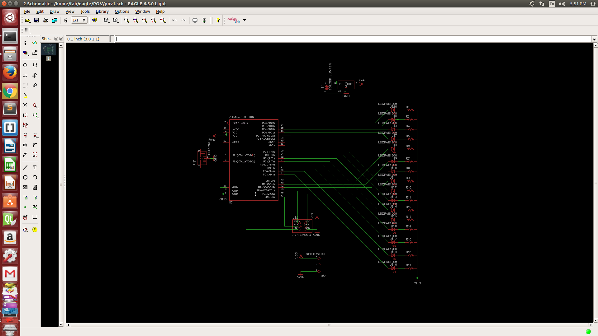
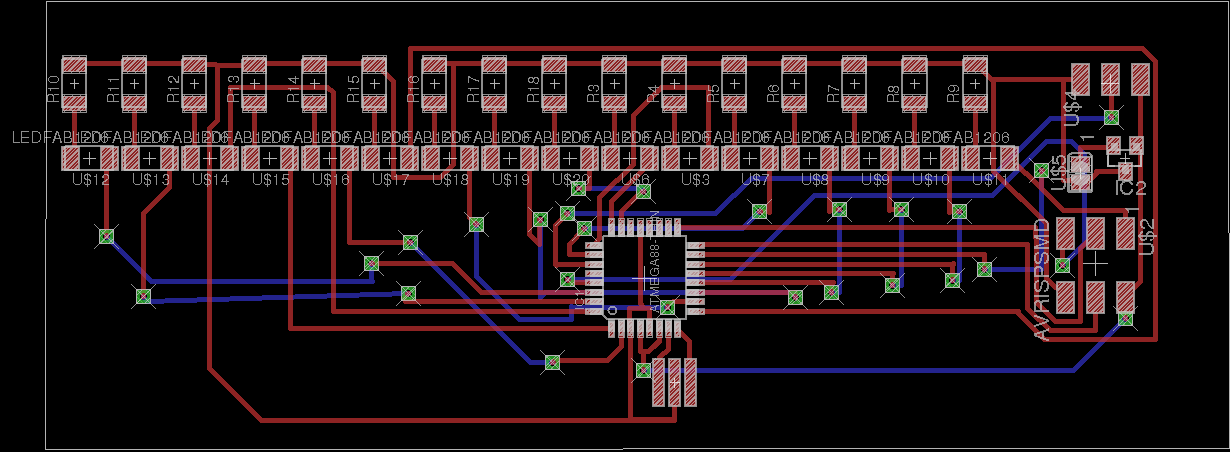
I designed the scematic diagrom in eagle. Here is the screenshot of both schematic and board.
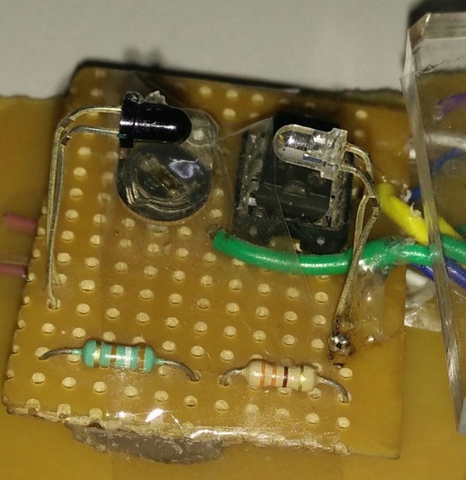
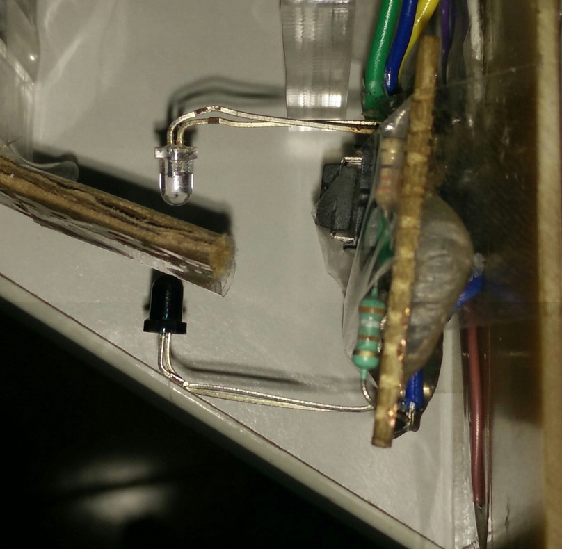
I used a a feedback system using IR Led and sensor for measuring the rpm.I have already made this before and this is not a printed circuit board. I made it in dotted PCB using wires.
I use a BLDC motor for high rpm using a bldc controller made by sibu.
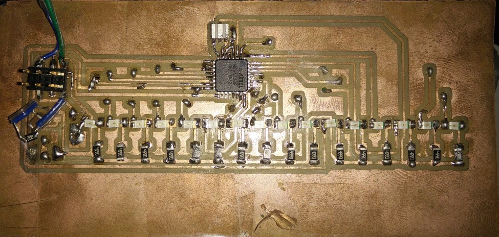
Here is the final video of the propeller display.
Problem faced
I used a feed back module for measuring the rpm and calculating the delay. In my code i measure the current rpm and calculate the delay and apply it for the next rotation. In this case the if the rpm fluctuates suddenly it will affect negatively. So the display was not proper when i used the delay calculated from feedback module. One of the reason was the wight was not balanced when i mounted the PCB and battery on the motor. So the rpm was varying and the rotation was not symmetrical. Finally i calculated a delay by trial and error method guessing many values.
Downloads
Propeller display Code, Schematic , Board , mill