She really likes walking during rainy ugly days...
But she does not like to walk on dirty and dry grounds...
To be honest, Fab Snail does not like many things...like polluted air or muggy days...
She is not the only one who doesn't like all that, just like all the other snails...
The difference is that if Fab Snails is not happy, she can turns into a real stalker!
(Also on your mobile -.-)
So take care of Fab Snail, she is a good snail...
She is just different from the other snails!"
Pressfit Kit
Make a Pressfit Cardboard Kit
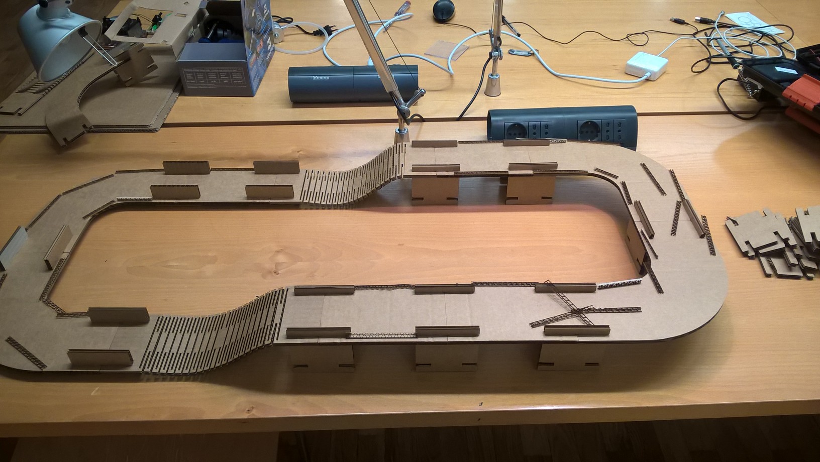
For the weekly assignment, I've decided to build a cardboard car track.
First of all, I've started to cut little squares on the cardboard in order to calculate the kerf of the laser cutter.
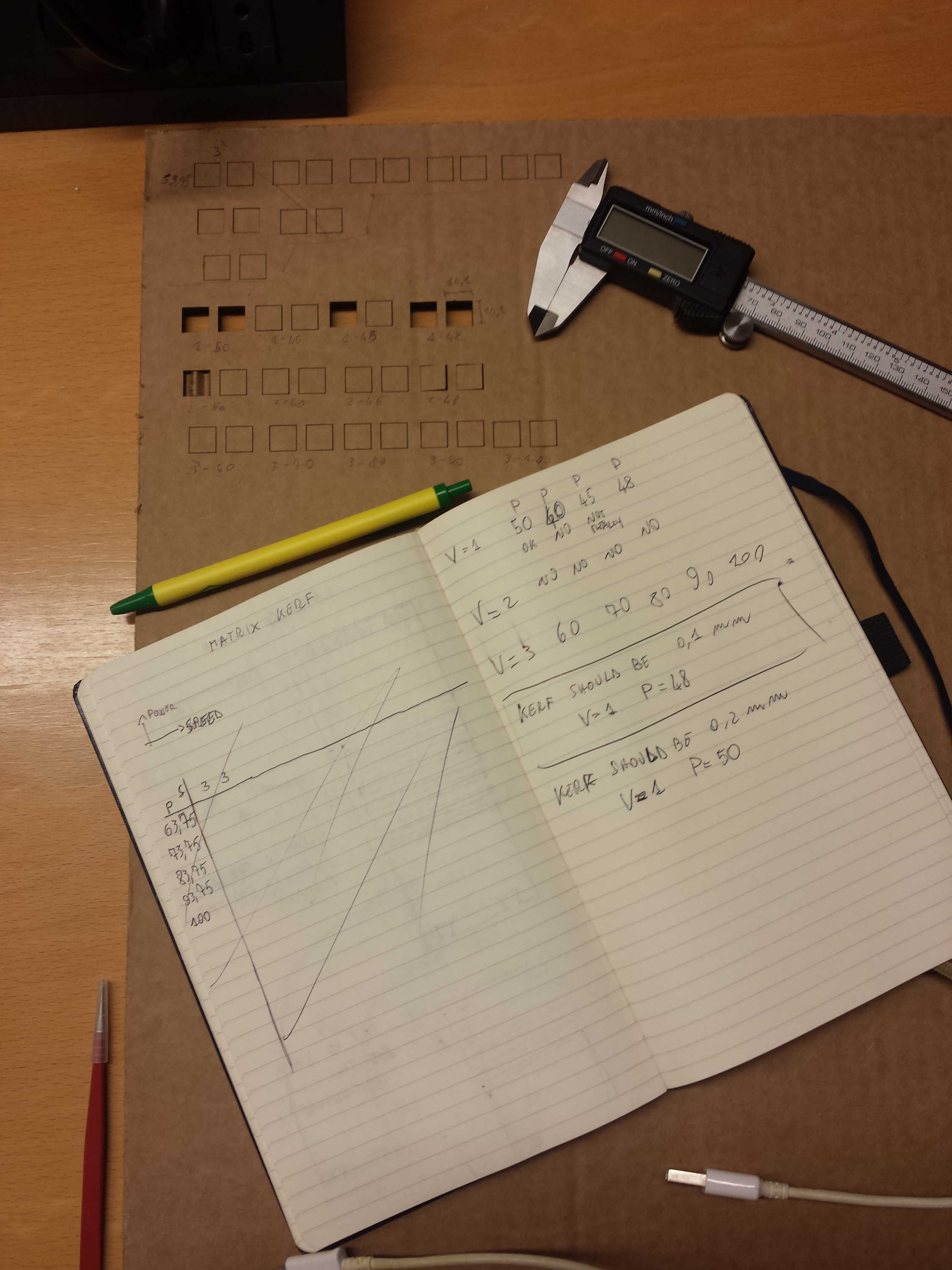
I found that the optimal settings which minimize the kerf for my machine (and for the cardboard that i've used) are:
- Power: 48%
- Speed: 1
Measuring the squares, supposed to be 10mm x 10mm, I found a length of 10,1 mm. So the kerf of the material was of 0,05mm.
Once the kerf was discovered, I had to decide what software to use for the modeling. Due to the fact that last week i've used Solid Works for modeling a sort of a snail shell (I want to stress “a sort of”...), i've decided to try a different software and I ended up choosing antimony.
The main reason that pushed me toward the choice was that Antimony is a parametric modeling software. This means that, after fixing some variables, is possible to correct errors and dimensions of the model simply by changing variables value. But I will talk later on this document about antimony.
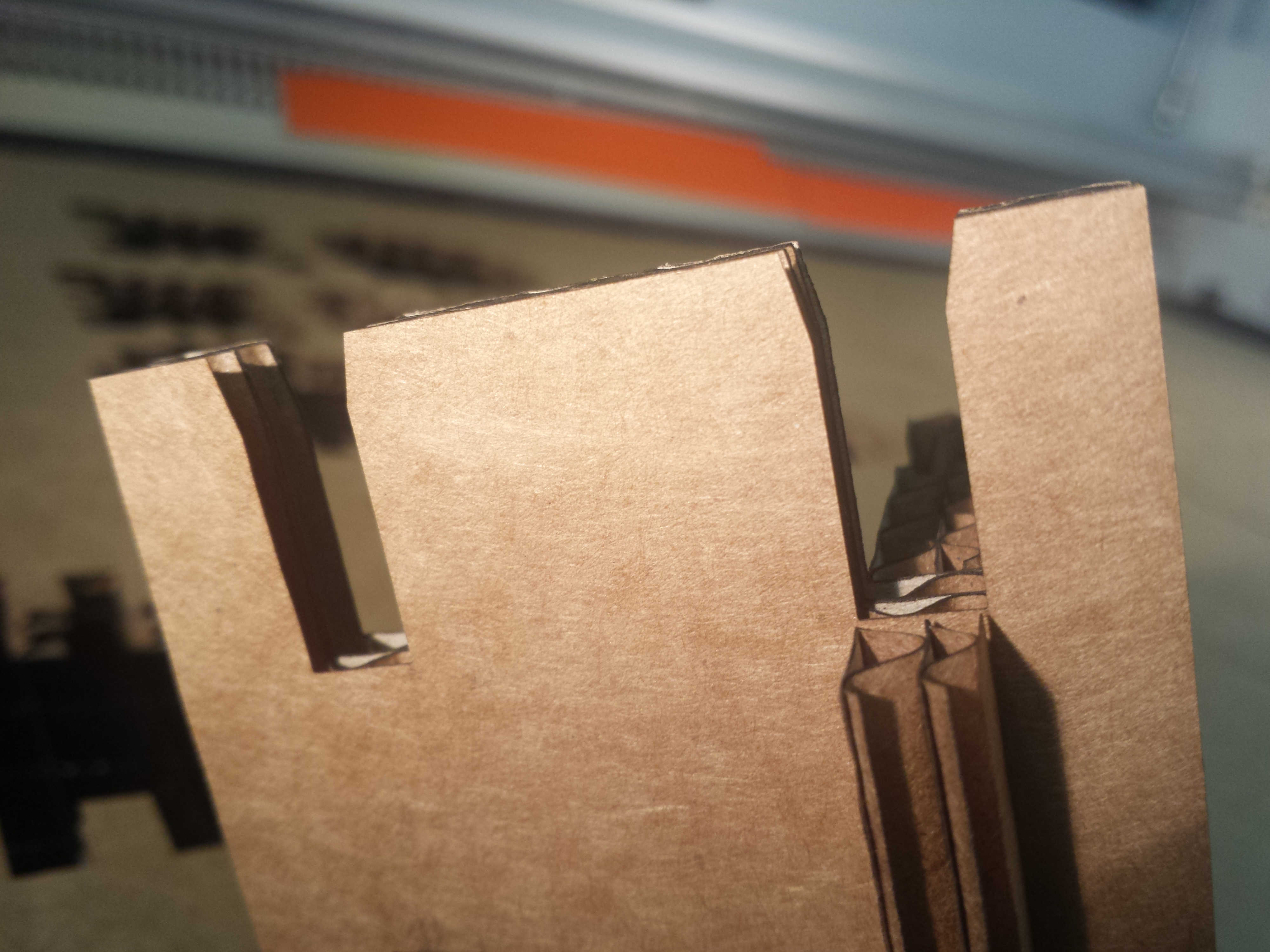
At this point, I started to test different types of joints. In particular, i've realized 2 different type of joints:
1) Plain joint
This Joint really sucks! The cardboard tends to loose the superficial layer when you start to stress the joint. Moreover, my pieces presents a non-simmetrical structure. On the left part of the joint, the width of the cardboard is smaller (1cm) than the inner part so it is subject to fracture.Test Inc by wakitowaki on Sketchfab
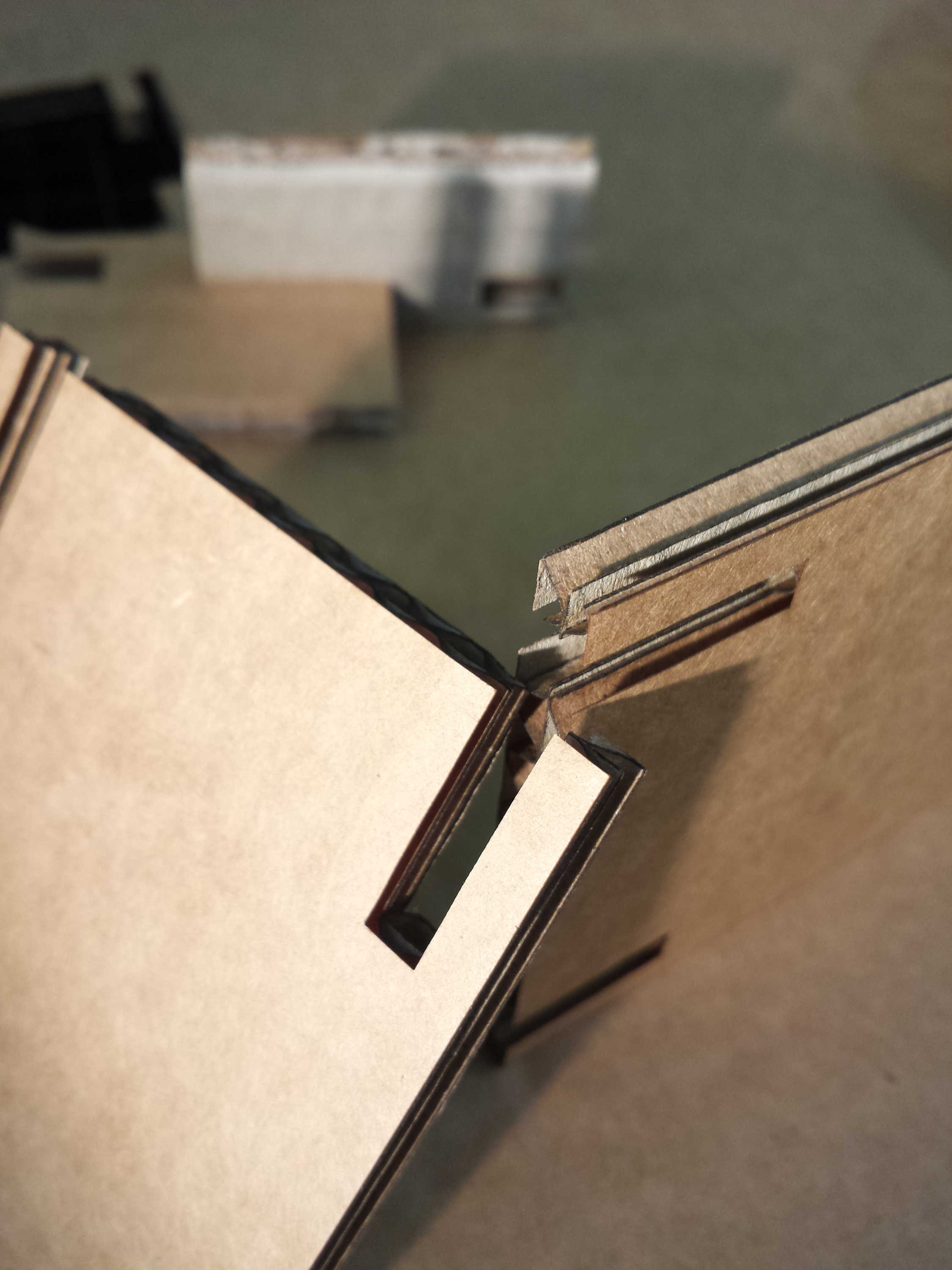
2) Compressive joint
This Joint rocks!
I've called it “compressive” because this joints compress a little bit the cardboard at the beginning.
It presents a non-straight line at the beginning which has a twofold purpose, it can “guide” the cardboard pieces to go towards the inner part of the hole and it compress the card board at the beginning.
I am sure that this is not the best solution, but it worked preatty well in my case.
After some tries, I ended up with a working joint.
Incastro Corretto by wakitowaki on Sketchfab
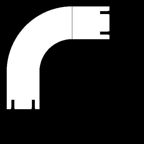
In my original idea, I wanted to have different heights for my track so I had to find a solution for bend the cardboard. After some searches, I ended up in this awesome site:
I found almost anything about bending patterns for different materials. In particular, this section is really really helpful (http://www.deferredprocrastination.co.uk/blog/2011/laser-cut-lattice-living-hinges/).
There are all the mathematical specification to calculate how to bend materials to simulate different behaviours. There are also some pre-defined patterns to use. It would be really nice to make some calculation in the future and to do so some experiments.
Once i've found a working joint, I proceed with the modeling and what I've obtained is a parametric model of all the pieces. (DOWNLOAD FINAL.SB ---> open it with antimony)
Finalfinal by wakitowaki on Sketchfab
And this is the real object:
Antimony
I would like to spend some words on antimony and to decribe the workflow that I followed to obtain my final object and to explain why I really like this software!!At a first glance i feel a little bit disoriented in using Antimony due to the fact that I could not find a huge documentation for the software. I started here:
Then i found these other useful links which helped me in understanding the software:
- http://fabacademy.org/archives/2015/doc/antimony_tabs.html
- https://github.com/mkeeter/antimony
- http://www.mattkeeter.com/projects/graph/
I found very useful to start with the exploration of the built-in functions. There are a lot of pre-defined shpes with a set of parameters that can be tuned freerly. I started making some circles and extrusions in the perspective view simply dragging the points but I really don't like this approach.
I feel more confortable in defining parametric relations between objects by modifying t he attributes of every block. In this way, I can define constants and contraints at the beginning and build all my model based on relative relations among objects. Any change of the initial parameters is immediately propagated to all the blocks related to that variables.
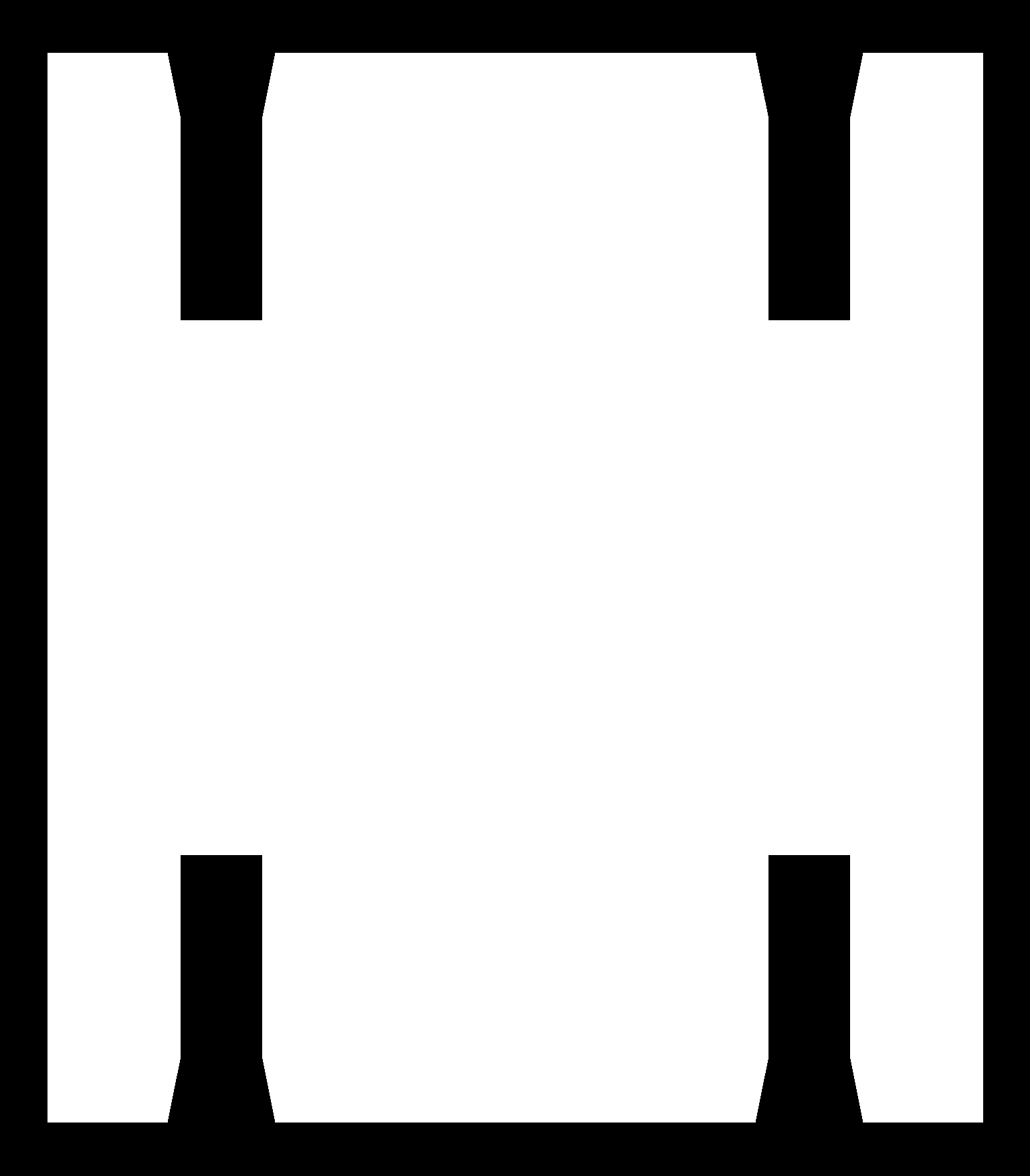
After i've acquired some confidence with the software, I started to make the pieces. After making a piece, antimony gives the possibility to export any single shape inside the realized patch simply connecting a block (called Export -.-) to the shape to export. It is possible to export in .PNG or in .STL settings the numbers of voxels per unit.
What I obtained was an image in black and white like the one below:
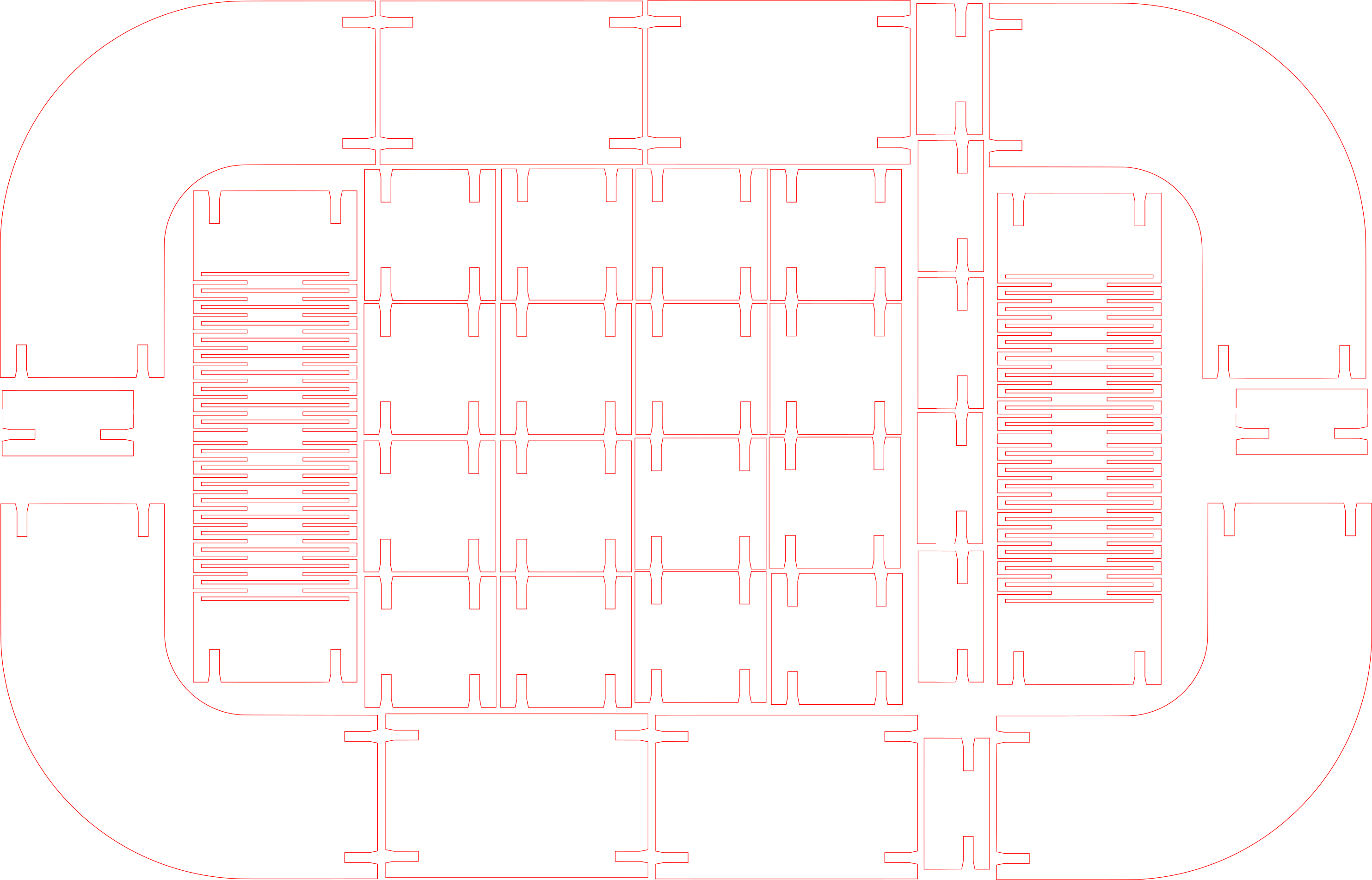
After this I've imported the image in inkscape to invert the image and to obtain a vectorial trace. In inkscape:
- Open image
- Go to Path → Trace bitmap
- Select Invert Image
- Click okay
Then, delete the background and edit the properties of the image. In particular, select the No fill options and adjust the contours stroke color and thickness accordingly to the laser cutting settings.
In the end I obtained something like this:
I had some troubles in exporting in antimony.
I found that sometimes in antimony, when two edges are coincident, the export will draw a line between the shapes.
I found that this behaviour is not related to the function used to melt the shapes (I tried both Union and Blend function and the result was exactly the same).
This is not a big problem but I do not like the solution to manually edit the picture with an image editor or with inkscape (moreover, modifing the vectorialized image was a little bit c omplex in inkscape because i had to move all the nodes and recontruct the traces).
So, I found that a possible work around is to overlap a little bit the shapes before blending :).
Another very cool primitive that I want to explore in the future is the Function block. Reading here
I found that in the appendix A of Matt Keeter thesis, there are a description on how the function works and what kind of notation is needed to write the functions. What I've actually understood is that the notation used is the Polish notation. I've found a precise description on wikipedia:
And I've also found this article which explains how to convert regular expression to polish notation using a simple algorithm:
Others awesome features that I really like in antimony are:
- Minimalism : there are no buttons with strange, not comprhensible icons. The functions are identified by their names….an extrusion is called….well…extrude.
- Python integration : is possible to directly import python libraries in each script
- Speed : the software runs smoothly and it is super fast
- Open source : the software is open source
I would like to learn more about this software which really “comes from a parallel universe”….i think I will go deeply in studying antimony.
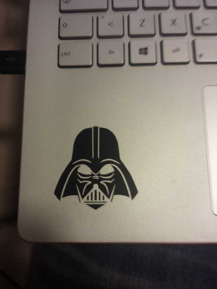
Vynil Cutting
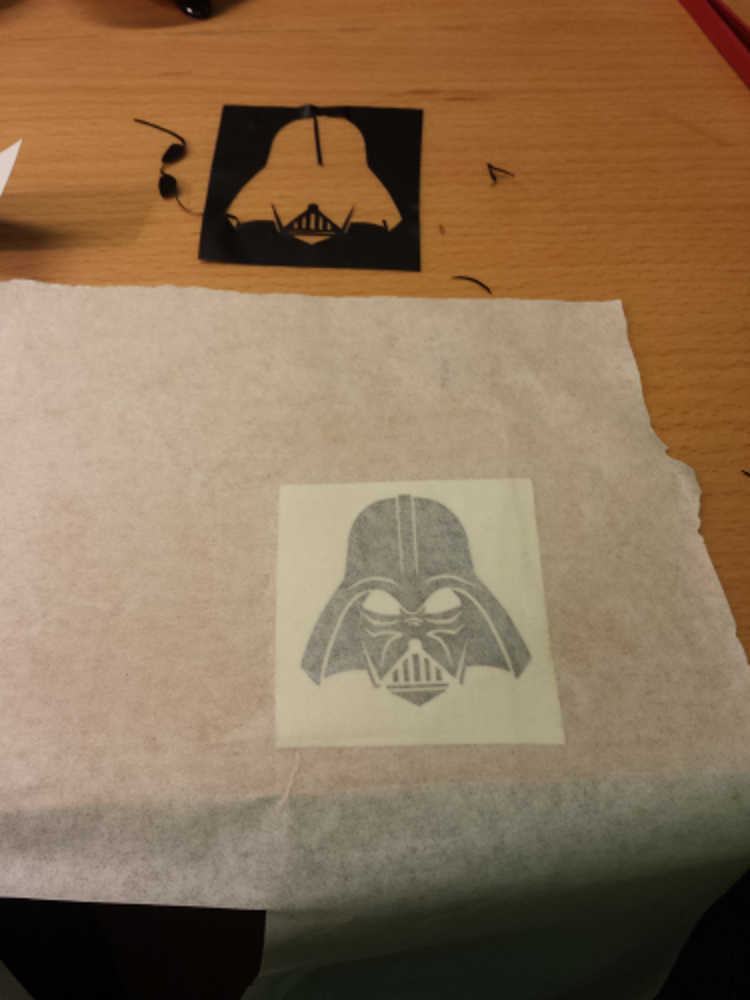
Concearning the vynil cutter, i've realized a Darth Vader sticker(PNG - camm).
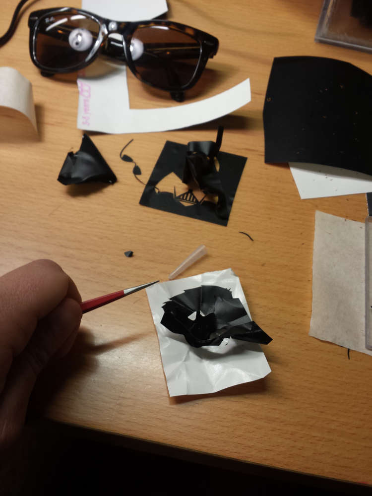
And then....i rage quitted on an hulk sticker because it was really small and full of very small pieces and i was
not able to keep everything in place when i was passing the vynil to the transfer tape... (PNG - camm)
The vynil cutter is a great machine and i found really interesting the fact that
our instructor Fiore showed to us that is possible to use the machine with a normal cat command
directly from the shell
cat *.camm > /dev/usb/lpX # with X the number assigned to the machineI passed through inkscape to generate the vectorial file and then through the fab modules to generate the .camm file.
Conclusions
This week was one of the most interesting since the beginning of Fab Academy. The think that i liked most is Antimony. The software can appear really complicated at the beginning but i think that spending time on it could result in a good investement. What i really like is the possibility to interact with any single part of the drawing both from the graphical interface and from the manipulation by maths on the panels. I would like to explore more in depth the potentiality of this software.