She really likes walking during rainy ugly days...
But she does not like to walk on dirty and dry grounds...
To be honest, Fab Snail does not like many things...like polluted air or muggy days...
She is not the only one who doesn't like all that, just like all the other snails...
The difference is that if Fab Snails is not happy, she can turns into a real stalker!
(Also on your mobile -.-)
So take care of Fab Snail, she is a good snail...
She is just different from the other snails!"
Weekly Assignment
The weekly assignment was:
- design and build a wired or wireless network connecting at least two processors
Software and Hardware
The software that i've used this week are:
- Eagle: used for designing the boards
- Arduino IDE: used to program the boards
- NodeMCU flasher: used to program the ESP8266
Concerning the hardware:
- Roland SRM20: CNC mill
I2C communication
I've decided to start with the I2C communication.
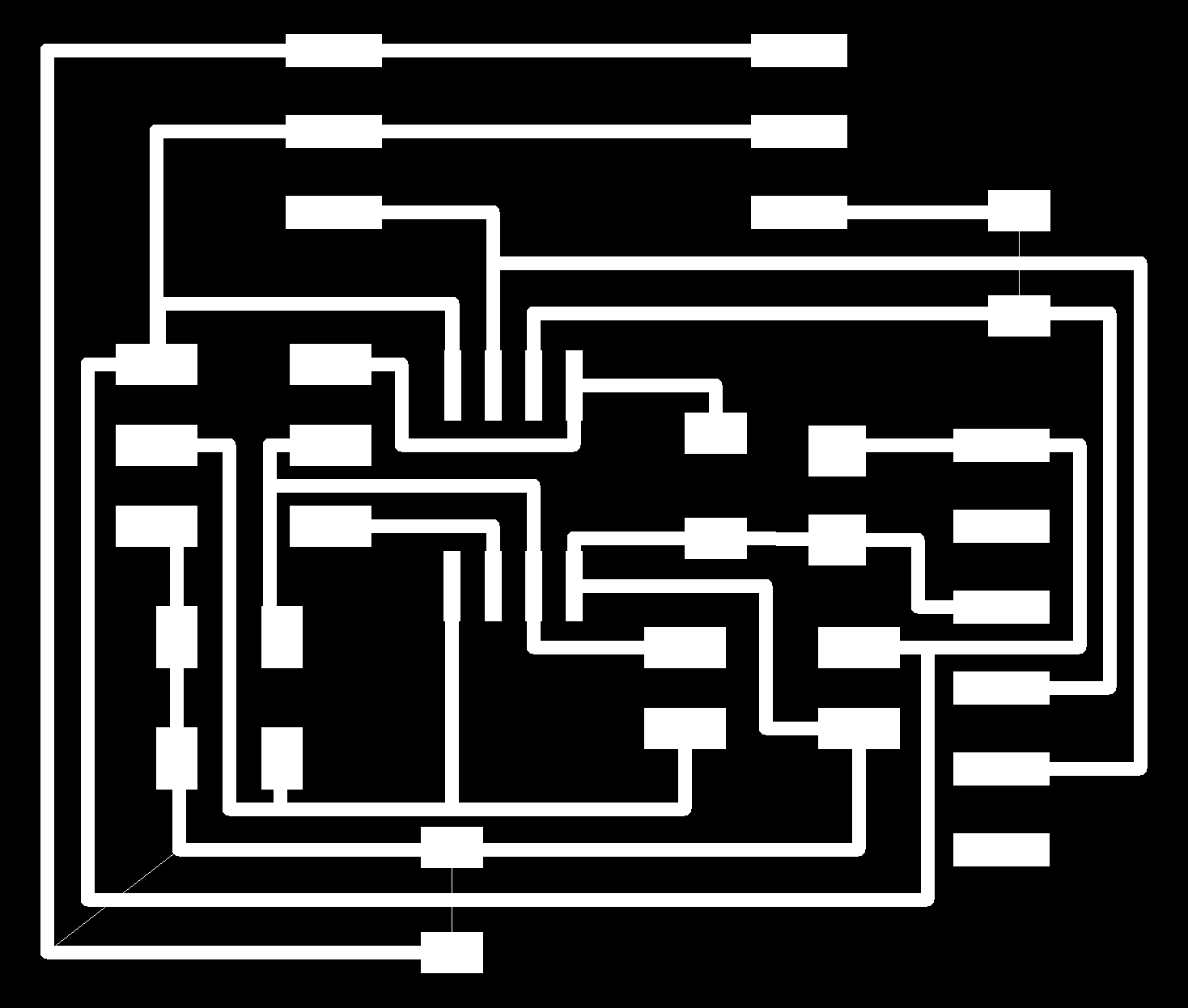
I've milled a board with an attiny45 microcontroller and i've realized two 3-pin connectors to attach
different sensors to the microcontroller.(DOWNLOAD Board - Schematic)
Then i've start to look for some documentation on the internet and i've found this
tutorial.
I've downloaded the TinyWireS library from here.
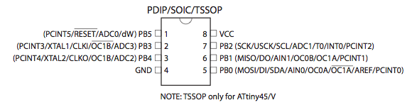
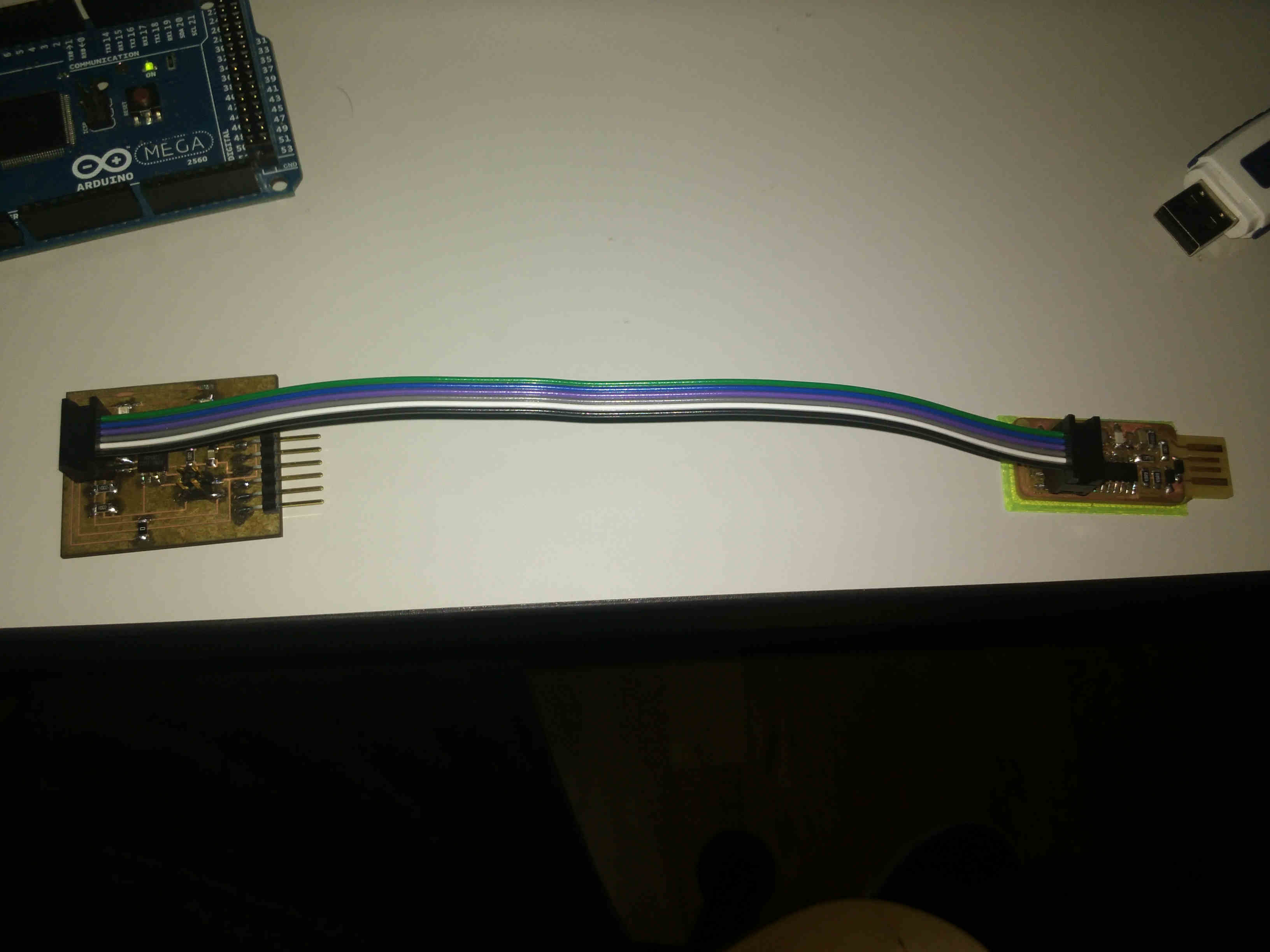
I had an Arduino Mega in the lab so i've decided to connect my board to that arduino. First of all, i've connected the Arduino
to my board following the pinout of the attiny 45:
Then i've located the I2C pin for the Arduino mega:
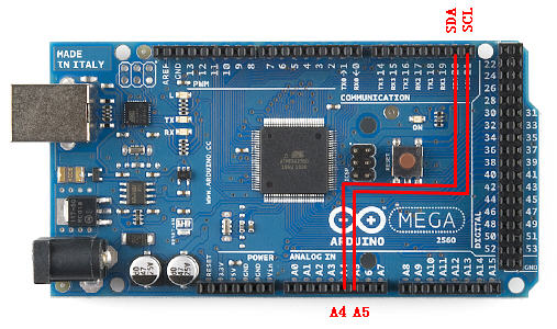
Then i've connected the two boards:
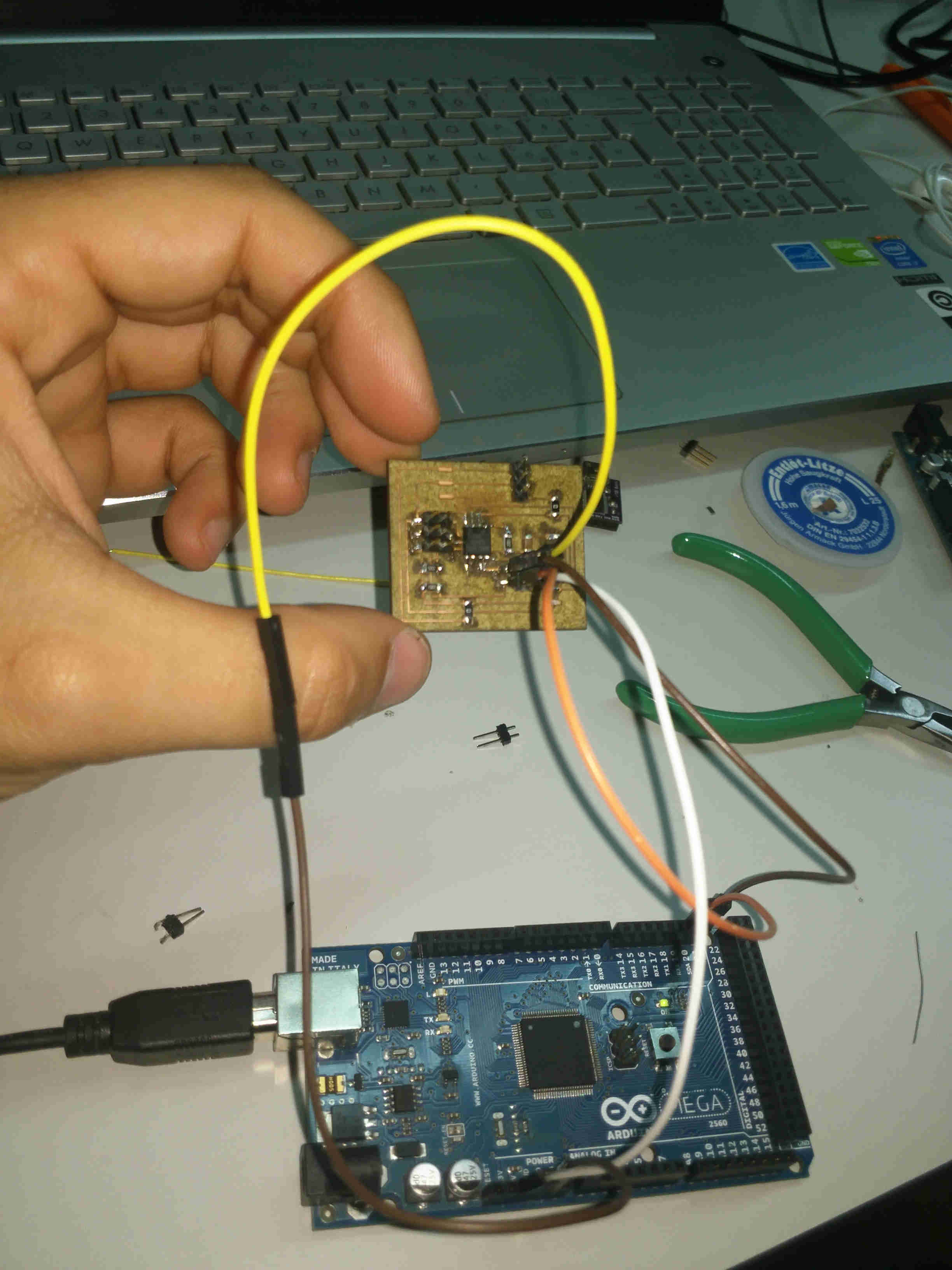
The code that i've used is different for the master (the Arduino Mega) and for the slave (my board):
//Code for the Arduino Mega<
  #include <Wire.h>

  void setup()
  {
   Wire.begin(); // join i2c bus (address optional for master)
   Serial.begin(9600); // start serial for output
  }

  void loop()
  {
   Wire.requestFrom(4, 1); // request 1 byte from slave device address 4

  while(Wire.available()) // slave may send less than requested
   {
   int i = Wire.read(); // receive a byte as character
   Serial.println(i); // print the character
   }

  delay(500);
  }
And this is the code for the slave:
#define I2C_SLAVE_ADDRESS 0x4 // Address of the slave

#include <TinyWireS.h>

int i=0;

void setup()
{
    TinyWireS.begin(I2C_SLAVE_ADDRESS); // join i2c network
    TinyWireS.onRequest(requestEvent);

    // Turn on LED when program starts
    pinMode(1, OUTPUT);
    digitalWrite(1, HIGH);
}

void loop()
{
    // This needs to be here
    TinyWireS_stop_check();
}

// Gets called when the ATtiny receives an i2c request
void requestEvent()
{
    TinyWireS.send(i);
    i++;
}
I've used the FabISP to upload the code to the slave-board.
The communication worked and i was able to retrieve numbers sended by the slave by reading the serial port of the master through the serial monitor of the arduino.
Once i've tested this, i've decided to replace the 3-pin connectors on the board with LEDs and i've used the same protocol to test the communication with more than one board.
Theese are the modified sketches:
//Code for the Arduino Mega
#include <Wire.h>

void setup()
{
 Wire.begin(); // join i2c bus (address optional for master)
 Serial.begin(9600); // start serial for output
}

void loop()
{
 Wire.requestFrom(4, 1); // request 1 byte from slave device address 4
 Wire.requestFrom(5, 1); // request 1 byte from slave device address 5
 Wire.requestFrom(6, 1); // request 1 byte from slave device address 6
while(Wire.available()) // slave may send less than requested
 {
 int i = Wire.read(); // receive a byte as character
 Serial.println(i); // print the character
 }

delay(500);
}
And for the code on the slaves, the only think that i've changed is the address of the device for each node (4-5-6 in this case).
#define I2C_SLAVE_ADDRESS 0x4 // Address of the slave, change it for each slave!
#include <TinyWireS.h>
int i=0;
int sensor=0;
void setup()
{
TinyWireS.begin(I2C_SLAVE_ADDRESS); // join i2c network
//TinyWireS.onReceive(receiveEvent); // not using this
TinyWireS.onRequest(requestEvent);
pinMode(3, OUTPUT);
pinMode(4, OUTPUT);
// Turn on LED when program starts
//pinMode(1, OUTPUT);
//digitalWrite(1, HIGH);
}
void loop()
{
// This needs to be here
TinyWireS_stop_check();
}
// Gets called when the ATtiny receives an i2c request
void requestEvent()
{
digitalWrite(3, HIGH); //light up first led
digitalWrite(4, LOW); //light up second led
delay(1000);
digitalWrite(3, LOW); //turn off first led
digitalWrite(4, HIGH); //turn off second led
delay(1000);
TinyWireS.send(i);
i++;
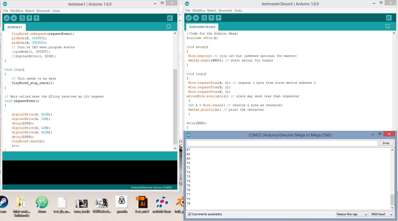
}Here is the result of the readings from the serial monitor and a video of the boards connected.
ESP8266 Module
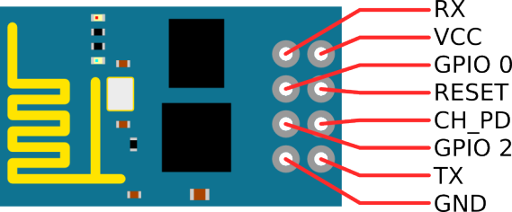
For this week i've tested also the ESP8266-01 module.
I've found this 7 tutorials to get started
with the module. First of all, this is the pinout of the module:
To program the board, is important to use a 3.3v ftdi cable (or a programmer) and to wire the ESP to the programmer in
the following way:
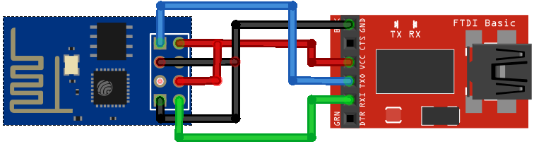
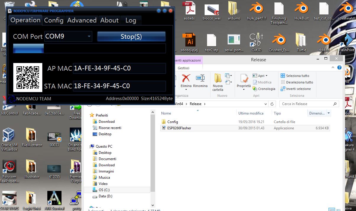
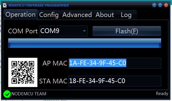
Then i've downloaded the NODEmcu flasher from github (LINK) in order to
flash the latest firmware on the ESP board.The flashing operation went fine:
Then i've installed the support for the ESP board for the Arduino IDE. I've used the board manager support by adding this URL link
in the preferences of the IDE (http://arduino.esp8266.com/stable/package_esp8266com_index.json). To upload the code, is important to put
the device in programming mode. This can be done manually (connetting the GPIO0 pin to ground and then, after uploading, connecting it to Vcc)
but it is really annoying to repeat the procedure each time you have to upload the code. FOr this reason i've decided to use the board
designed by my instructor Fiore Basile. The schematics can be found
o his github repository (github).
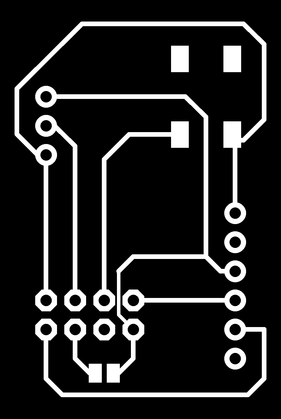

I've modified a little bit the board by adding a pin on the line of the GPIO0 which was not exposed (is the green line on the image).To
upload sketches on the board is necessary (after having selected the board from the "board menu" in the arduino IDE) to press and hold
the pushbutton on the board and wait until the sketch is loaded. After the upload, just disconnect the power from the board and reconnect it
without pressing the button.
I've made a first experiment by using the Esp as a web server. This is the code that i've uploaded on the device:
/*********
  Rui Santos
  Complete project details at http://randomnerdtutorials.com
*********/

#include <ESP8266WiFi.h>
#include <WiFiClient.h>
#include <ESP8266WebServer.h>
#include <ESP8266mDNS.h>

MDNSResponder mdns;

// Replace with your network credentials
const char* ssid = "OpenUnisi";
const char* password = "";

ESP8266WebServer server(80);

String webPage = "";

int gpio0_pin = 0;
int gpio2_pin = 2;

void setup(void){
  webPage += "<h1>ESP8266 Web Server</h1><p>Socket #1 <a href=\"socket1On\"><button>ON</button></a> <a href=\"socket1Off\"><button>OFF</button></a></p>";
  webPage += "<p>Socket #2 <a href=\"socket2On\"><button>ON</button></a> <a href=\"socket2Off\"><button>OFF</button></a></p>";

  // preparing GPIOs
  pinMode(gpio0_pin, OUTPUT);
  digitalWrite(gpio0_pin, LOW);
  pinMode(gpio2_pin, OUTPUT);
  digitalWrite(gpio2_pin, LOW);

  delay(1000);
  Serial.begin(115200);
  WiFi.begin(ssid, password);
  Serial.println("");

  // Wait for connection
  while (WiFi.status() != WL_CONNECTED) {
    delay(500);
    Serial.print(".");
  }
  Serial.println("");
  Serial.print("Connected to ");
  Serial.println(ssid);
  Serial.print("IP address: ");
  Serial.println(WiFi.localIP());

  if (mdns.begin("esp8266", WiFi.localIP())) {
    Serial.println("MDNS responder started");
  }

  server.on("/", [](){
    server.send(200, "text/html", webPage);
  });
  server.on("/socket1On", [](){
    server.send(200, "text/html", webPage);
    digitalWrite(gpio0_pin, HIGH);
    delay(1000);
  });
  server.on("/socket1Off", [](){
    server.send(200, "text/html", webPage);
    digitalWrite(gpio0_pin, LOW);
    delay(1000);
  });
  server.on("/socket2On", [](){
    server.send(200, "text/html", webPage);
    digitalWrite(gpio2_pin, HIGH);
    delay(1000);
  });
  server.on("/socket2Off", [](){
    server.send(200, "text/html", webPage);
    digitalWrite(gpio2_pin, LOW);
    delay(1000);
  });
  server.begin();
  Serial.println("HTTP server started");
}

void loop(void){
  server.handleClient();
}
Once the code is uploaded, by opening the serial monitor is possible to see the ip address assigned to the ESP device:
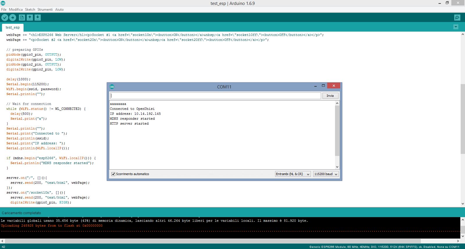
By navigating that IP i can access the interface to control the GPIO's pin of the ESP.

After this first exploration, i've moved into a little bit more complicated experiment. My idea was to communicate via I2C protocol using the ESP as a master and an arduino as a slave in order to control the servo motors. I want to use this kind of interaction in my final project by replacing the arduino with a custom motor board with a 2 channel H-bridge to drive the motors of the snail.
I've used the following code for the ESP-master:
#include <Wire.h>

#define ADDRESS 5


void setup() {
  // put your setup code here, to run once:
  Serial.begin(115200);
  Wire.begin(0,2);
  delay(15);
}

void loop() {
  // put your main code here, to run repeatedly:
  while (Serial.available()){
    char c = Serial.read();
    if (c == 'H'){
      Wire.beginTransmission(ADDRESS);
      Wire.write('H');
      Wire.endTransmission();
      Serial.println("H sent");
    }

    else if (c == 'L'){
      Wire.beginTransmission(ADDRESS);
      Wire.write('L');
      Wire.endTransmission();
      Serial.println("L sent");
    }
    }

}


byte slaveRead()
{
Wire.requestFrom(ADDRESS,1);

while(!Wire.available())
{

}
return Wire.read();

}
And this is the code for the Arduino-slave:
#include <Wire.h>

#include <Servo.h>

Servo myservo;

void setup() {
  // put your setup code here, to run once:
  Wire.begin(5);
  Wire.onReceive(receiveEvent);
  pinMode(20, OUTPUT);
  pinMode(21, OUTPUT);
  digitalWrite(20, HIGH);
  digitalWrite(21, HIGH);
  Serial.begin(115200);
  delay(150);
}

void loop() {
  // put your main code here, to run repeatedly:

}

void receiveEvent(int howMany){

  while(Wire.available()){
    char c = Wire.read();

    if (c == 'H'){
      myservo.attach(9);
      delay(10);
      myservo.write(0);
      delay(10);
      Serial.println("H recieved");
      }

    else if (c == 'L'){
      myservo.attach(9);
      delay(10);
      myservo.write(90);
      delay(10);
      Serial.println("L received");
      //myservo.detach();
      }
    }
}
To retrieve information about the Arduino libraries for the ESP i've just used the official documentation on github at this address (https://github.com/esp8266/Arduino).
The following video shows the result:
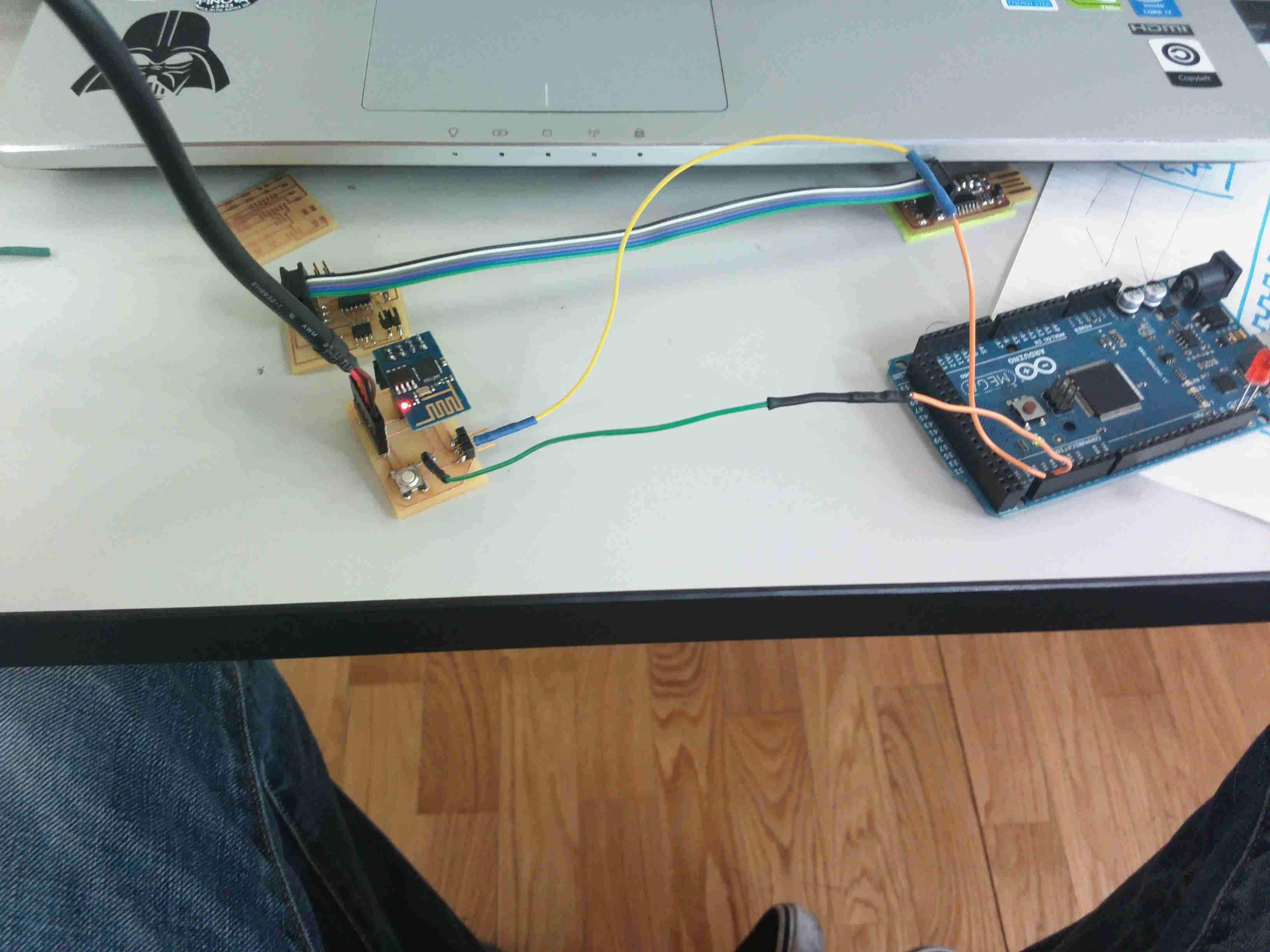
Obviously, due to the fact that this model of the ESP has only 2 GPIOs pins, i've used both of them for the I2C communication. As you can see, the two pins goes directly into the SDA and SCL pins of the Arduino Mega.
Conclusions
This module was particularly useful because it gives me the opportunity to reflect on the networking part that i want to use in my final project. My idea is to use the ESP8266 to control through I2C protocol the boards that will drive the motors of the snail. Morevoer i've never used the ESP before and i was happy to discover this easy-to-use platform which is similar to an arduino but which costs ten time less and has a built-in wi-fi. I think that the ESP-01 is not enough in many applications because it has only two GPIO pins, but i've seen that there are twelve different models of the board whit a lot more free pins.