She really likes walking during rainy ugly days...
But she does not like to walk on dirty and dry grounds...
To be honest, Fab Snail does not like many things...like polluted air or muggy days...
She is not the only one who doesn't like all that, just like all the other snails...
The difference is that if Fab Snails is not happy, she can turns into a real stalker!
(Also on your mobile -.-)
So take care of Fab Snail, she is a good snail...
She is just different from the other snails!"
Weekly Assignment
The weekly assignment was:
- Design a 3D mold, machine it, and cast parts from it
Software and Hardware
The software that i've used this week are:
- Eagle: used for designing the boards
- OpenCV: used to program the python sketch for blob recognition
- Python
Concerning the hardware:
- Roland SRM20: CNC mill
Designing the boards
For the weekly assignment i've decided to build 2 boards and to explore OpenCV framework
because i would like to connect a blob recognition operation with a physical output board.
I've decided to build an h-bridge to control a DC motor (which i want to use in my final project to move
the snail) and a solenoid to control the one that i've used in the machine building week.
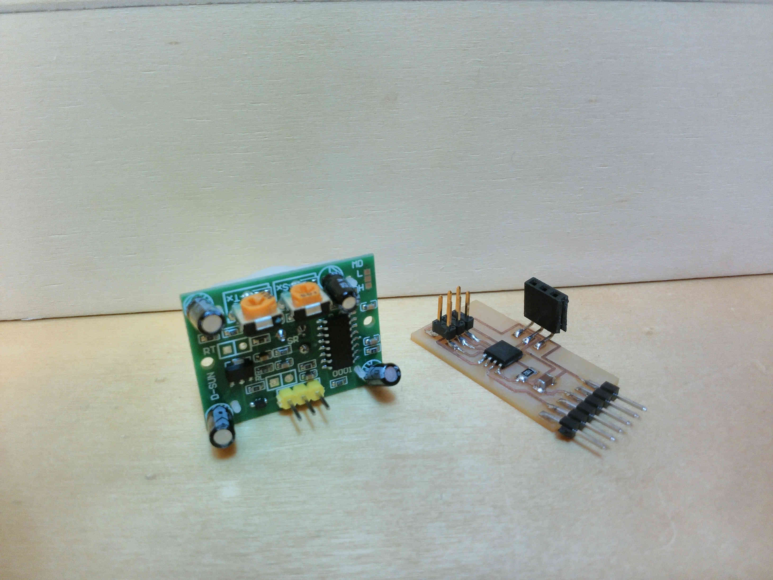
I've also builded the pyroelectric input board because i want to test it to use for a project that
i want to build during the composites week.
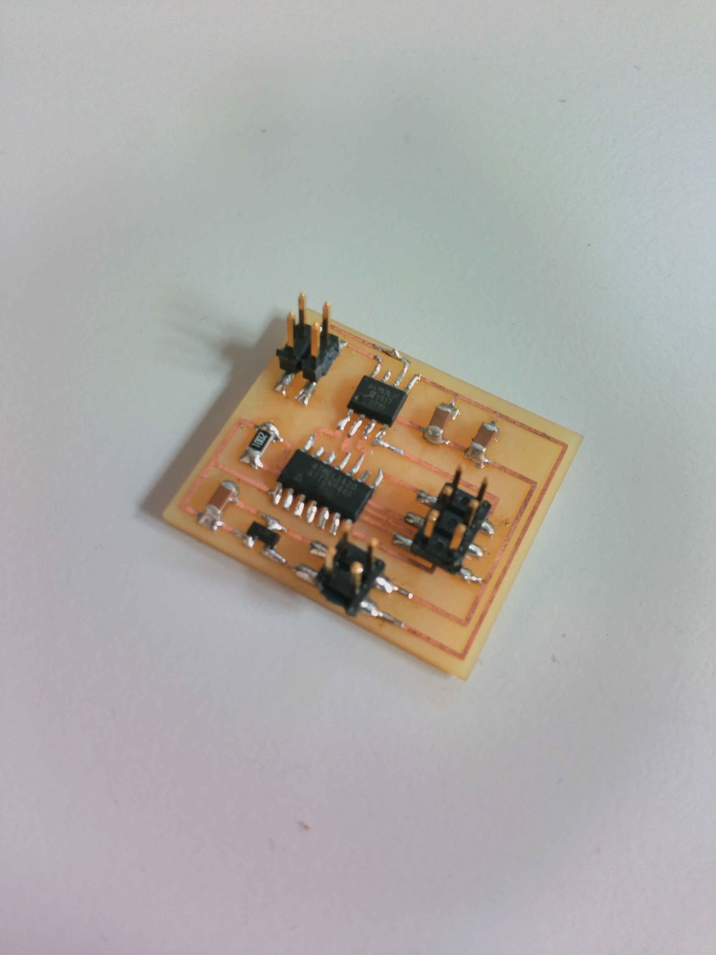
Here are the boards that i've builded:
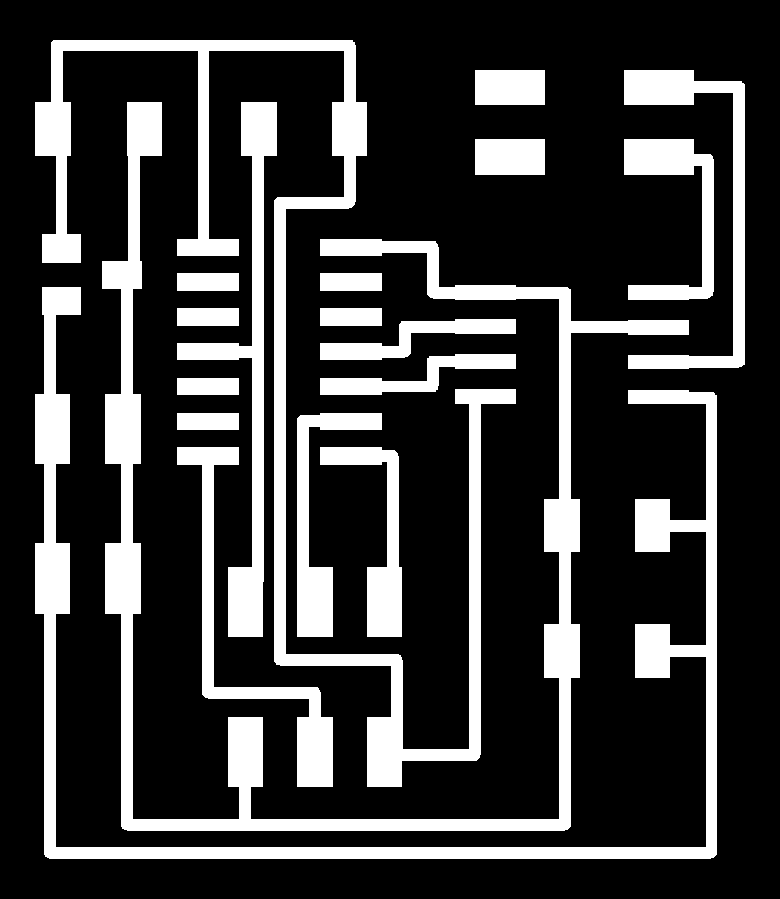
DC motor H-bridge (SCHEMATIC - BOARD):
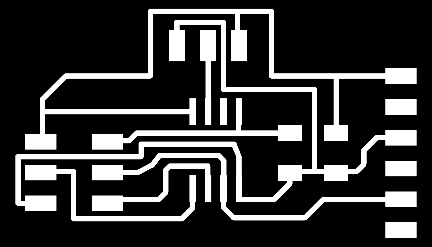
Unfortunately i'm still waiting for a PIR sensor that i've ordered so i've only builded the board without the sensor
(SCHEMATIC - BOARD):
After i've milled the boards, i've programmed it through the FabISP.I've started from Neil's C files
for the DC motor and then i've modified the code to adapt it to the solenoid:
//
//
// hello.H-bridge.44.DC.c
//
// H-bridge DC motor hello-world
//
// Neil Gershenfeld
// 11/18/12
//
// (c) Massachusetts Institute of Technology 2012
// This work may be reproduced, modified, distributed,
// performed, and displayed for any purpose. Copyright is
// retained and must be preserved. The work is provided
// as is; no warranty is provided, and users accept all
// liability.
//

#include "avr/io.h"
#include "util/delay.h"

#define output(directions,pin) (directions |= pin) // set port direction for output
#define set(port,pin) (port |= pin) // set port pin
#define clear(port,pin) (port &= (~pin)) // clear port pin

#define on_delay() _delay_us(100000) // PWM on time
#define slow_off_delay() _delay_us(300000) // PWM off time

#define bridge_port PORTA // H-bridge port
#define bridge_direction DDRA // H-bridge direction
#define IN1 (1 << PA3) // IN1
#define IN2 (1 << PA2) // IN2

int main(void) {
   //
   // main
   //

   //
   // set clock divider to /1
   //
   CLKPR = (1 << CLKPCE);
   CLKPR = (0 << CLKPS3) | (0 << CLKPS2) | (0 << CLKPS1) | (0 << CLKPS0);
   //
   // initialize H-bridge pins
   //
   clear(bridge_port, IN1);
   output(bridge_direction, IN1);
   clear(bridge_port, IN2);
   output(bridge_direction, IN2);
   //
   // main loop
   //
   while (1) {

         //
         // turn forward
         //
         clear(bridge_port, IN1);
         set(bridge_port, IN2);

            set(bridge_port, IN2);
            on_delay();
            clear(bridge_port, IN2);
            slow_off_delay();

         //
         // turn reverse
         //
         clear(bridge_port, IN2);
         set(bridge_port, IN1);

            set(bridge_port, IN1);
            on_delay();
            clear(bridge_port, IN1);
            slow_off_delay();
   }
 }
I've removed part of the code because i just wanted a push pull behaviour of the solenoid.I've realized that to have a visible effect, the delay must be of about one second othervise the solenoid starts vibrating and the inversion of the position is not visible at all.
Moreover, i've tried to find information about the solenoid that i had in the lab but the datasheet that i've found is in chinese (DATASHEET). If i've understood correctly, the duty cycle of the solenoid should be 1/3 seconds at 1A and 5V. It means that it should stay on for a second and then off for 3. So i've setted the two delays to one and three seconds respectively.This is the result:
This is the DC motor instead:
I will test the PIR sensor as soon as i can get it.
OpenCV
I've used OpenCV to implement a blob recognition program. I want to connect this program to a physical
output board but this week i've only tested the blob recognition feature and i've connected it to an arduino
to test the serial communication.
I've started from this very detailed tutorial and then i've modified the code a little bit.Here is the final
version (DOWNLOAD):
# import the necessary packages
from collections import deque
import numpy as np
import argparse
import imutils
import cv2
import serial
import time
import re
import sys

class Comport:
    def __init__(self,com,speed):
        self.comport = com
        self.comspeed = speed

    def opencom(self):
        self.serial = serial.Serial(port=self.comport,baudrate=self.comspeed,timeout=5)

    def writeln(self,str):
        l_block = str.strip()
        self.serial.write(l_block + '\n')
        #print('writing : {}'.format(str))
        #self.serial.write(str)
        #self.serial.write(num)

    def readline(self):
        return self.serial.readline()

    def closecom(self):
        self.serial.close()
        print "closing COMport"

ap = argparse.ArgumentParser()
ap.add_argument("-v", "--video", help="path to video")
ap.add_argument("-b", "--buffer", type=int, default=64,help="maxbuffsize")
args = vars(ap.parse_args())

colorLower = (142, 102, 110)
colorUpper = (255, 255, 215)
pts = deque(maxlen=args["buffer"])
a = Comport("/dev/ttyACM0", 115200)
a.opencom()


if not args.get("video", False):
    camera = cv2.VideoCapture(0)
else:
    camera = cv2.VideoCapture(args["video"])

while True:
    (grabbed, frame) = camera.read()

    if args.get("video") and not grabbed:
        break

    frame = imutils.resize(frame, width=600)
    hsv = cv2.cvtColor(frame, cv2.COLOR_BGR2HSV)

    mask = cv2.inRange(hsv, colorLower, colorUpper)
    mask = cv2.erode(mask, None, iterations=2)
    mask = cv2.dilate(mask, None, iterations=2)
    cnts = cv2.findContours(mask.copy(), cv2.RETR_EXTERNAL, cv2.CHAIN_APPROX_SIMPLE)[-2]
    center = None

    if len(cnts) > 0:
        c = max(cnts, key = cv2.contourArea)
        ((x , y), radius) = cv2.minEnclosingCircle(c)
        M = cv2.moments(c)
        center = (int(M["m10"] / M["m00"]), int(M["m01"] / M["m00"]))
        print ((x,y))
        #a.writeln(str(float(x)))
        if x >= 300:
            a.writeln("dx")
            #time.sleep(.3)

        elif x < 300:
            a.writeln("sx")
            #time.sleep(.3)

        if radius > 10:
            cv2.circle(frame, (int(x), int(y)), int(radius), (0,255,255), 2 )
            cv2.circle(frame, center, 5, (0,0,255), -1)

    pts.appendleft(center)
    #print(center)

    for i in xrange(1, len(pts)):
        if pts [i -1] is None or pts[i] is None:
            continue

        thickness = int(np.sqrt(args["buffer"] / float(i + 1)) * 2.5)
        cv2.line(frame, pts[i -1], pts[i], (0,0,255), thickness)


    cv2.imshow("Frame", frame)
    key = cv2.waitKey(1) & 0xFF

    if key == ord("q"):
        break
a.closecom()
camera.release()
cv2.destroyAllWindows()
I've reused the controller that i've wrote for the machine building week to include the serial communication in this program.In the tutorial that i've linked above, the code is explained line by line. There is just one thing that could be useful that i want to underline. This program is based on the colour recognition and to change the color of the object is enough to change this values:
  colorLower = (142, 102, 110)
  colorUpper = (255, 255, 215)
To determine the parameters for the upper and lower bounds, i've used this python program (DOWNLOAD).
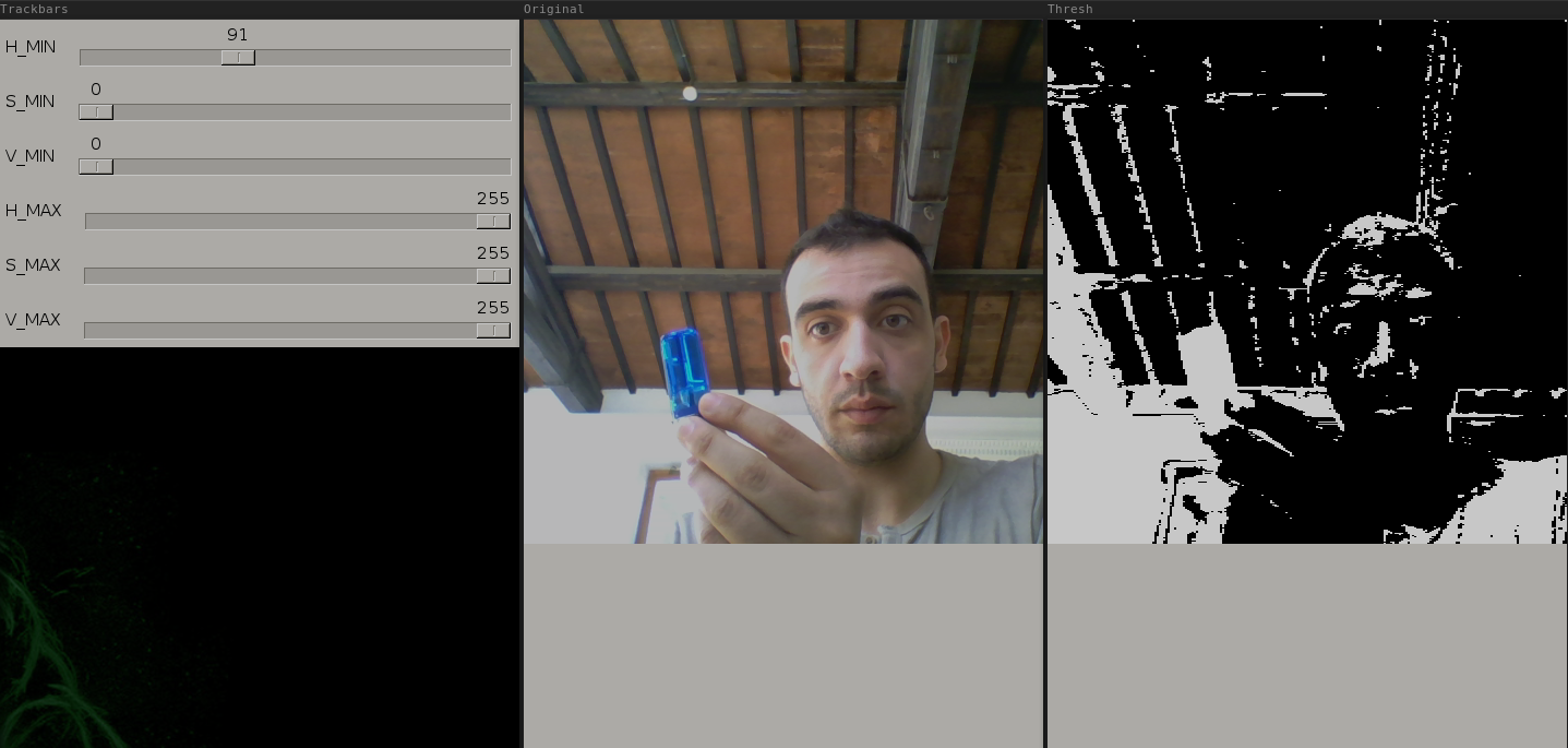
By adjusting the thresholds, you can mask all the image and when you have the object that you want to track white on black, you can write the values for the upper and lower bound of the color and you can change that values in the program for the recognition.
The program sends the string "dx" if the center of the object is located in the right side of the screen and "sx" if the center is in the left side. I've used this Arduino sketch to simply read the values from the serial port.
Conclusions
In this week i've tried to realize one of the board that i would like to include in my final project, the DC motor shield.
I've also decided to move some basic steps into the OpenCV framework and i think that it could be really useful in terms
of applications related to the output boards. Driving the boards using the object recognition technique is really funny.
I've also found interesting that at this point i feel really confident using the SRM20 and i'm able to design and mill the
boards much more faster than some weeks ago.