Roosvelth Cántaro's Academy

This week, it was designed and implemented to record the integrated circuit ATTiny 44 and for verification was conducted some tests.
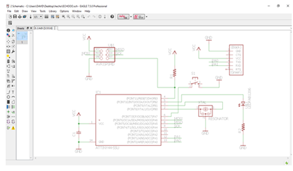
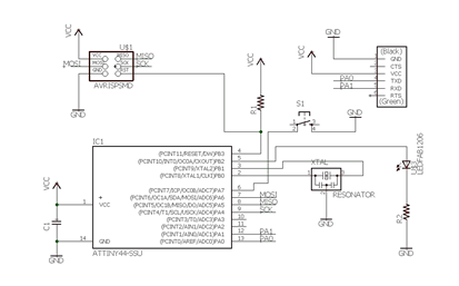
The first step was to design The Eagle program, you must first insert all components used in the schematic and then connect them after the board file which is to design the circuit is generated.
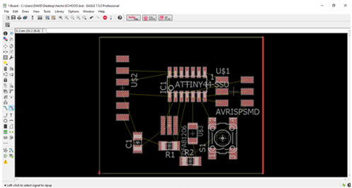
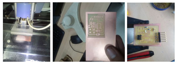
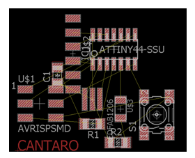
In the board file it was designed in a way that is the smaller printing plate, the design was made on the card upper face since the devices used technology were cmd.
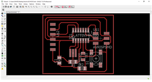
The first thing that was done was to accommodate the devices, and then routing it would draw the tracks on the circuit when the manual was completed routing gave us results in Figure 3.
Once finished the design, it is saved in a .PNG extension, it is saved in that extension in order to print on the router.
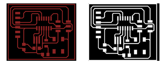
Once we finish milling plate, only you need to cut and solder the devices, note that the devices used are momentode cmd soldering technology and special care is needed for the temperature soldier will not burn.
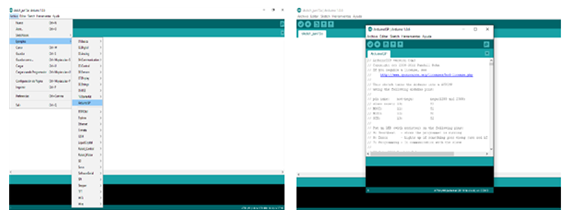
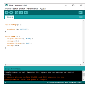
To test the operation of the circuit designed a program to perform this test is performed. We will use The arduino program.
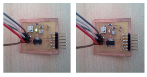
The first is to open the Arduino ISP to record programming on the board designed to check the circuit, which is the programming led flashing recorded.
Problem in the design of the scheme for the search for components to make the plate.
Solution:
Replace with another component that has the same measurement.
Problem when sending in the board of the program in the auto routing..
Solution:
Ruterar the track by hand
Datasheet:
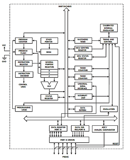
THE MICROCONTROLLER:
Ruterar the track by hand
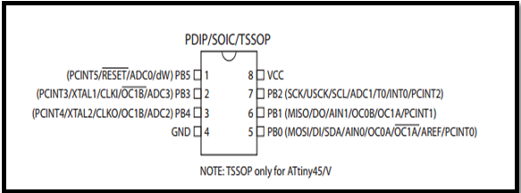
Pin Descriptions
1.1.1 VCC
Supply voltage.
1.1.2 GND
Ground.
1.1.3 Port B (PB5:PB0)
Port B is a 6-bit bi-directional I/O port with internal pull-up resistors (selected for each bit). The Port B output buffers have symmetrical drive characteristics with both high sink and source capability. As inputs, Port B pins that are externally pulled low will source current if the pull-up resistors are activated. The Port B pins are tri-stated when a reset condition becomes active, even if the clock is not running. Port B also serves the functions of various special features of the ATtiny45
1.1.4 RESET
Reset input. A low level on this pin for longer than the minimum pulse length will generate a reset, even if the clock is not running and provided the reset pin has not been disabled The reset pin can also be used as a (weak) I/O pin.
At the beginning it did not work well programming that I did, because we had an error programming the ATTINY 44. Another option was to record the board with the ARDUINO software and the programming was OK, using Arduino as ISP. Anyway, finally we exchanged the resonator, and the FabISP worked.