Roosvelth Cántaro's Academy

Add an output device to a microcontroller board you’ve designed and program it to do something.
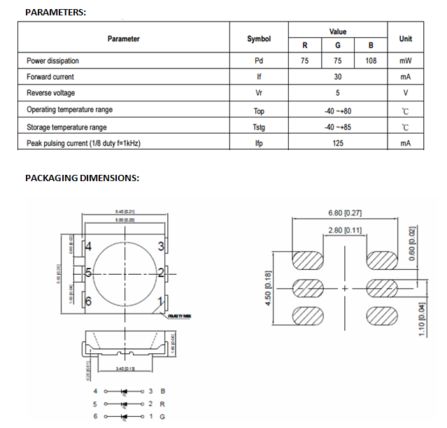
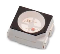
To assign OUTPUT I decided to do something that resembles an alarm or an indicator, and what convinced me was the RGB LED that could use three colors to act as indicators.
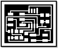
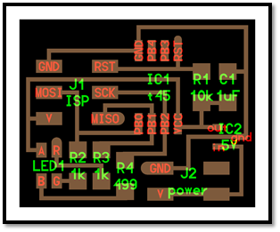
First I downloaded strokes RGB LED
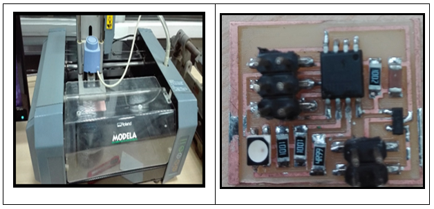
Then we moved to the milling machine to print the circuit board.
Once I have done the circuit board had to weld all the components showed me on the board.
After welding the components the plate is as follows:
After all the welding process, I got to check my circuit continuity because he had already had problems with those details.
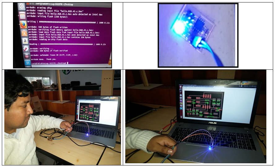
Finally, having reviewed all are happy with my plate; I went to program the ATtiny45. To this, I used Ubuntu and AVR.
The steps that I take to program the integrated were the following:
- Open the terminal.
- I locate files in programming, which was hello.RGB.45.make hello.RGB.45.C
- Then,I entered commands to program (sudo make–f hello.mic.45.make program- avrisp2)
With this we have set my output device.
The problem that was found in the circuit is to recognize whether the led RGB is common anode or common cathode.
Solution:
To do this test with a voltmeter is stepped to check its polarity.
Problem in the connections for proper programming of the micro controller.
Solution:
Use the manual of the micro controller to verify the pin configuration and programming
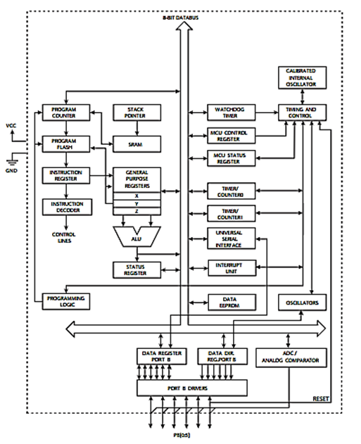
THE MICROCONTROLLER:
Ruterar the track by hand
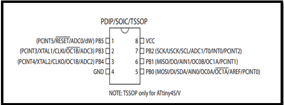
Pin Descriptions
1.1.1 VCC
Supply voltage.
1.1.2 GND
Ground.
1.1.3 Port B (PB5:PB0)
Port B is a 6-bit bi-directional I/O port with internal pull-up resistors (selected for each bit). The Port B output buffers have symmetrical drive characteristics with both high sink and source capability. As inputs, Port B pins that are externally pulled low will source current if the pull-up resistors are activated. The Port B pins are tri-stated when a reset condition becomes active, even if the clock is not running. Port B also serves the functions of various special features of the ATtiny45
1.1.4 RESET
Reset input. A low level on this pin for longer than the minimum pulse length will generate a reset, even if the clock is not running and provided the reset pin has not been disabled The reset pin can also be used as a (weak) I/O pin.
General Description The LM3480 is an integrated linear voltage regulator. It features operation from an input as high as 30V and a guaranteed maximum dropout of 1.2V at the full 100 mA load. Standard packaging for the LM3480 is the 3-lead SuperSOT® package. The 5, 12, and 15V members of the LM3480 series are intended as tiny alternatives to industry standard LM78LXX series and similar devices. The 1.2V quasi low dropout of LM3480 series devices makes them a nice fit in many applications where the 2 to 2.5V dropout of LM78LXX series devices precludes their (LM78LXX series devices) use. The LM3480 series features a 3.3V member. The SOT packaging and quasi low dropout features of the LM3480 series converge in this device to provide a very nice, very tiny 3.3V, 100 mA bias supply that regulates directly off the system 5V±5% power supply.
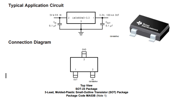
Key Specifications:
• 30V maximum input for operation
• 1.2V guaranteed maximum dropout over full load and temperature ranges
• 100 mA guaranteed minimum load current
• ±5% guaranteed output voltage tolerance over full load and temperature ranges
• −40 to +125˚C junction temperature range for operation
• Descriptions:
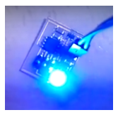
The Chip-LED Taping is much smaller than lead frame type components, thus enable smaller board size, higher packing density, reduced storage space and finally smaller equipment to be obtained. Besides, lightweight makes them ideal for miniature application, etc.