
This task has been very entertaining and I remembered what before had already studied when he was a student of TECSUP 16 years ago could have the opportunity to take basic courses of electronics.
Then, first thing I did was remind a little of resistors, capacitors, diodes, integrated circuits concepts and recognize the importance of these electronic devices in the development and growth of cutting-edge technology.
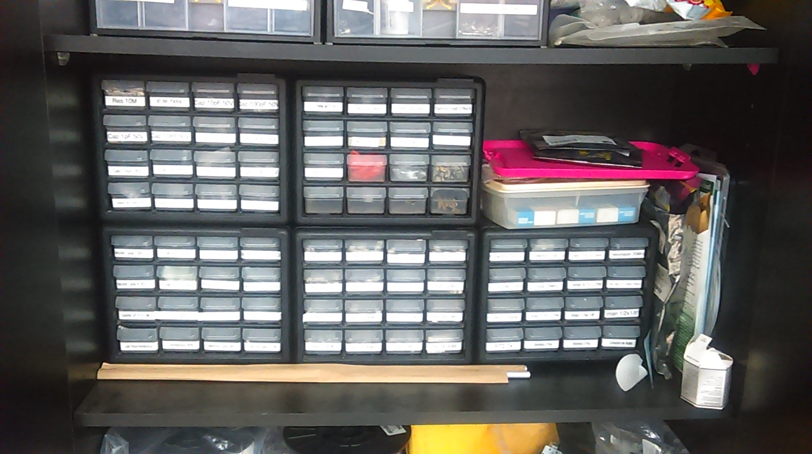
To begin work on this task, I started to identify all the tools for the job such as Roland model MDX-20, and other components to assemble my electronic circuit.
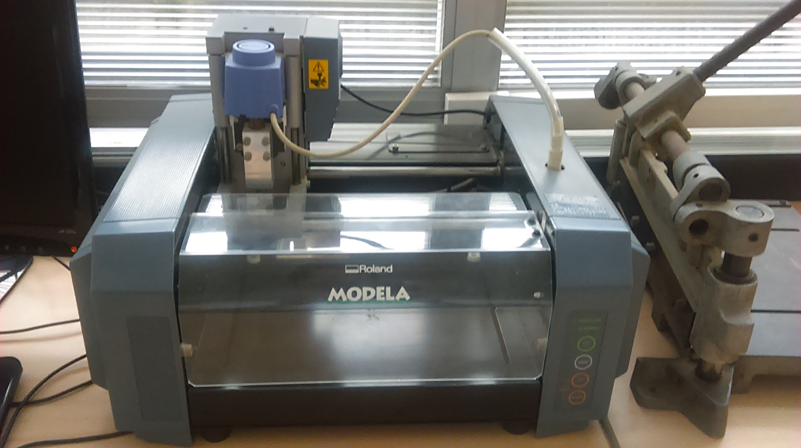
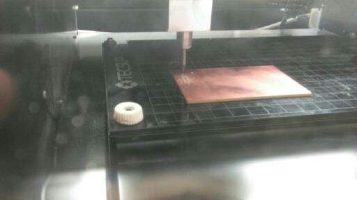
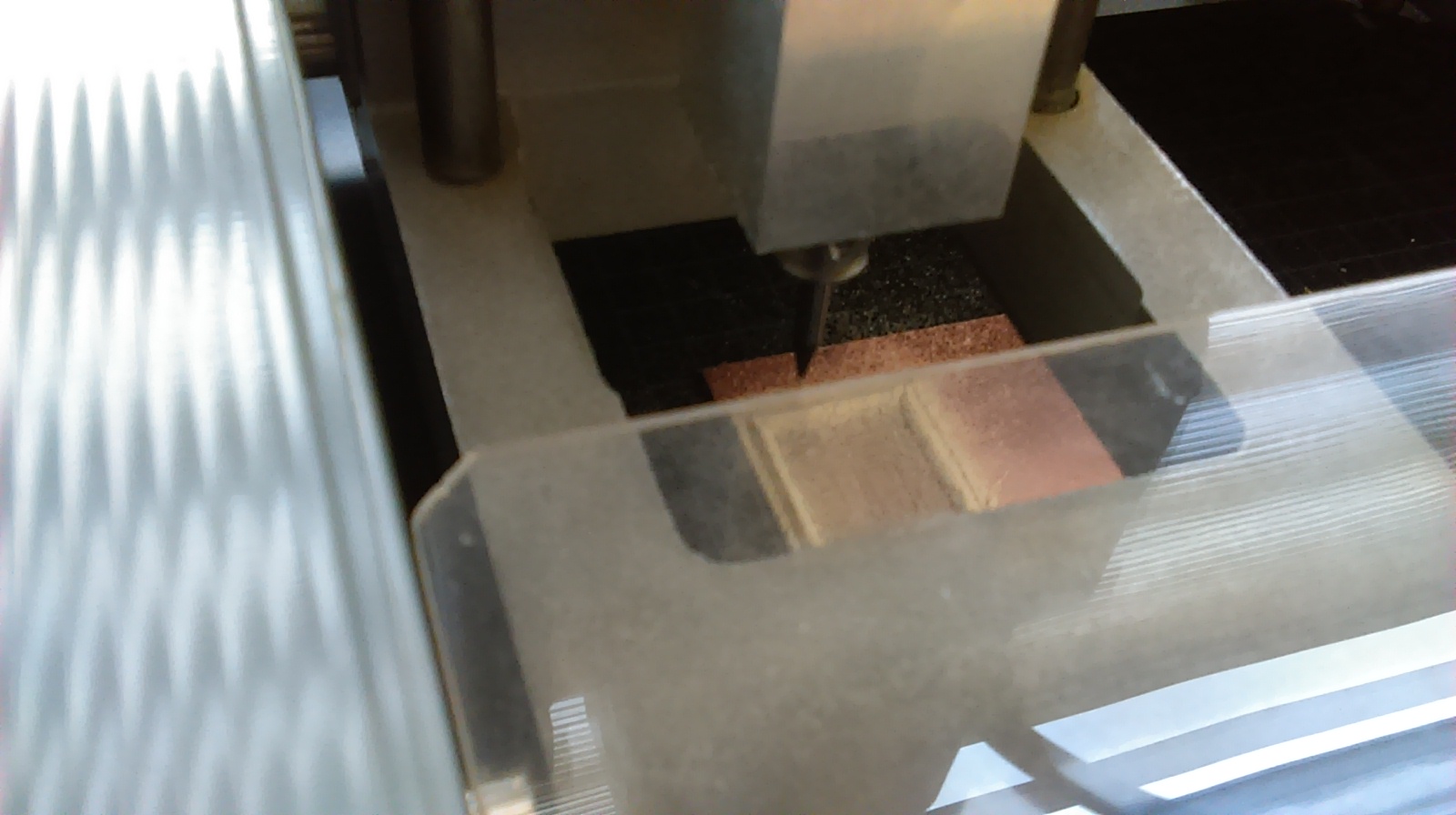
To begin the work with the card it had to stamp it, since in the computer already the scheme is formed to using, what I had to do was to give him the parameters to the computer to begin with the rectified one to the card that one was finding without entire.
I used Fabmodules to control the Modela MDX 20. Here you can see the parameters I used for milling the board. Since I dont have much experience soldering, people at Tecsup recomended me to mill using -1 offset, this way is easier to solder, because every road is very separated. The other parameters are used by default, except error, in this case I used 0.1. The diameter could be 0.38, but using 0.4 is better, because the traces are a little bit wider.

After the programming realized in the computer the machine Roland Model MDX-20 started rectifying the electronic plate since we can see in the imagesTo begin the work with the card it had to stamp it, since in the computer already the scheme is formed to using, what I had to do was to give him the parameters to the computer to begin with the rectified one to the card that one was finding without entire.
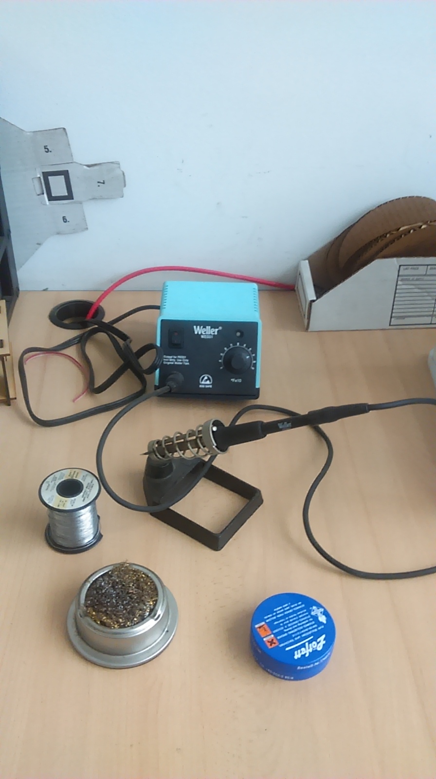
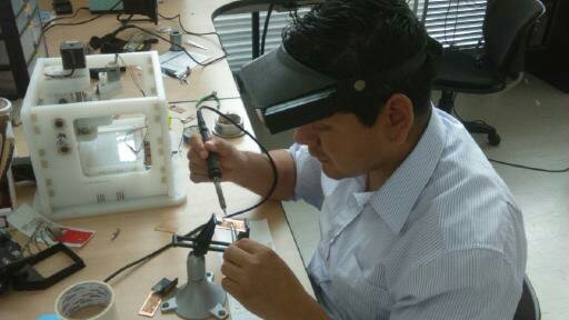
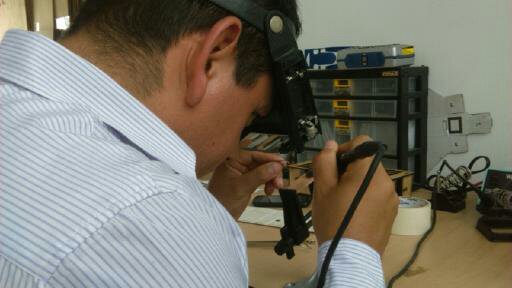
As soon as I had the electronic card and the electronic ready devices since I started welding, to the beginning I was not feeling comfortable since many years ago it was not welding with cautín but as the time was happening I think that it was welding better. Some pieces were very small so it had to use a magnifying glass to be able to visualize well the devices and not commit mistakes.
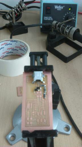
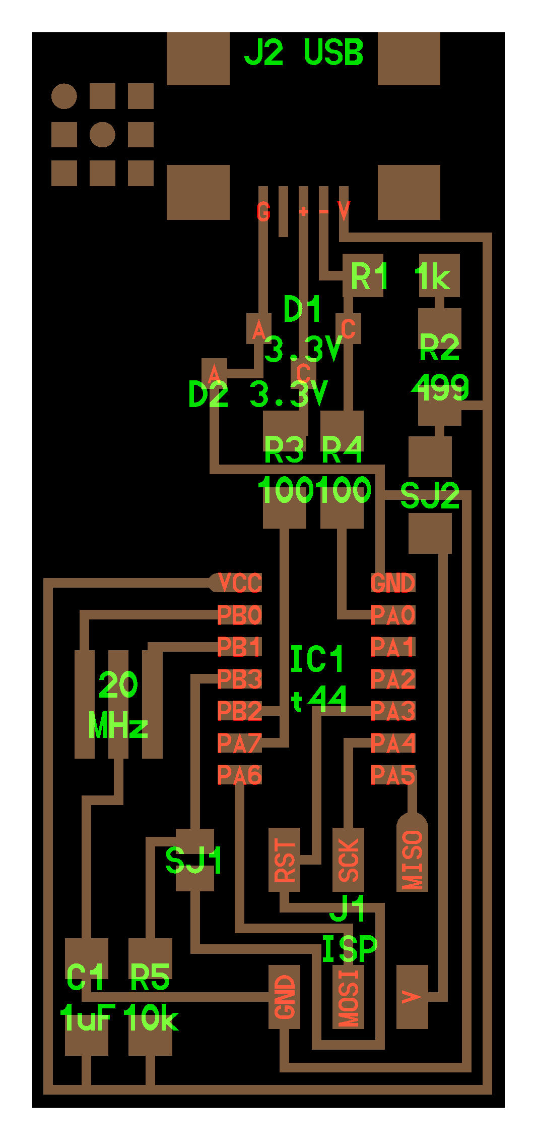
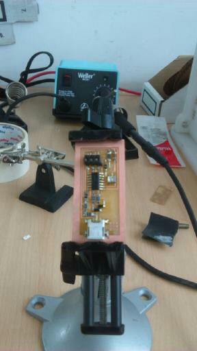
Finally I could weld all the components of my electronic circuit belonging to the task N°4 like it shows in the figure later.
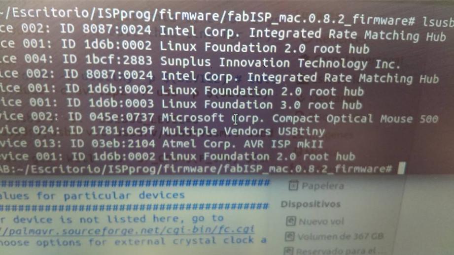
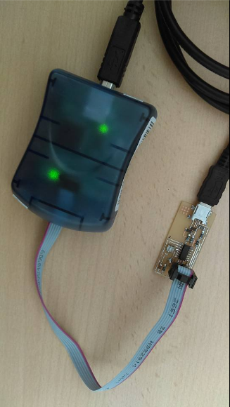
The last thing to do is to burn the .hex file on the board. For this I used the AVRISP and the FTDI cable. You can see in the next pictures that the FABISP is recognized for the PC
The conclusion that I could extract of this task is that I could remember the functioning of the electronic devices and understand the interrelationship between them. Another thing i found is that electronics are kind of tricky, and to have a second plan board is always a good idea.