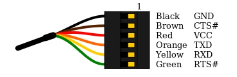
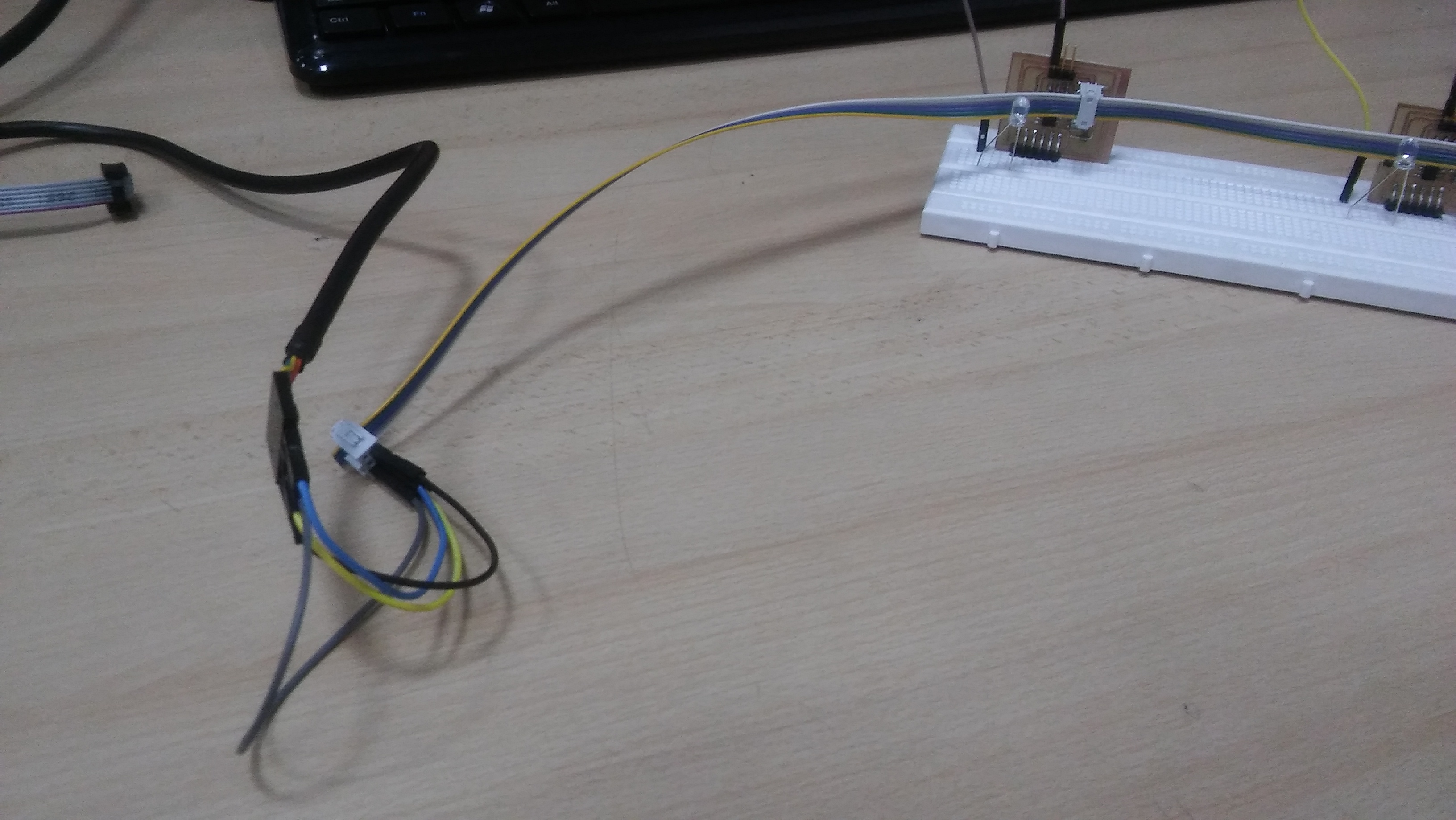
For this assignment, I used Serial Communication between 2 attiny boards and my PC. For this I used the FTDI cable to connect the two boards. I had a little trouble looking for the right pins for the boards. Since the FTDI has 4 important wires (VCC, GND, RX and TX), I just had to connect them to the ribbon wire using jumpers.
I show below the pictures of the datasheet I used
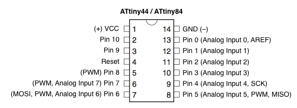
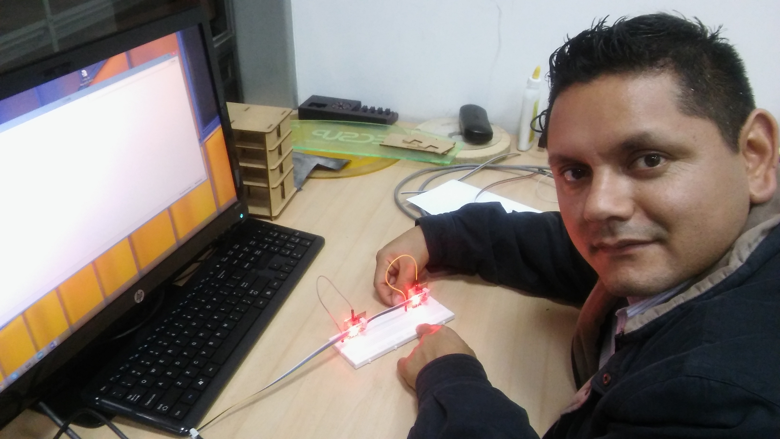
Since I programmed MISO and MOSI pins I used the ribbon wire and some jumpers to connect the FTDI at the right positions. The master is the computer and the slaves are the attiny boards. I used some leds to show how it works.
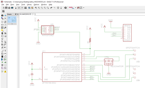
SCHEMATIC DESIGN IN EAGLE
BUTTON DESIGN IN EAGLE
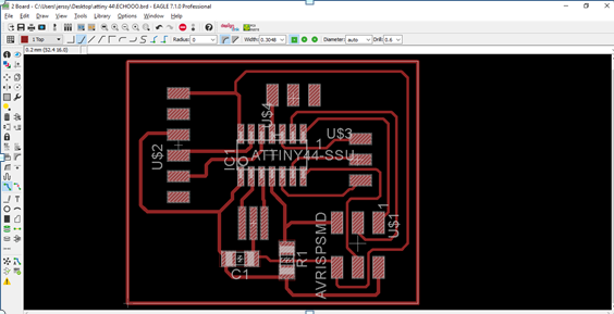
FINAL DESIGN USING MY PLATE ATtiny 44
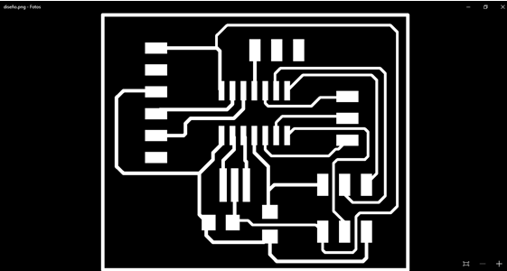
The reason I had to make a new design for ATtiny 44, was to be be me easier use of the pins.
One complication I had was that I could not do that syncs , and that was because we used a crystal 20MHz . And to solve that change it using the internal crystal .
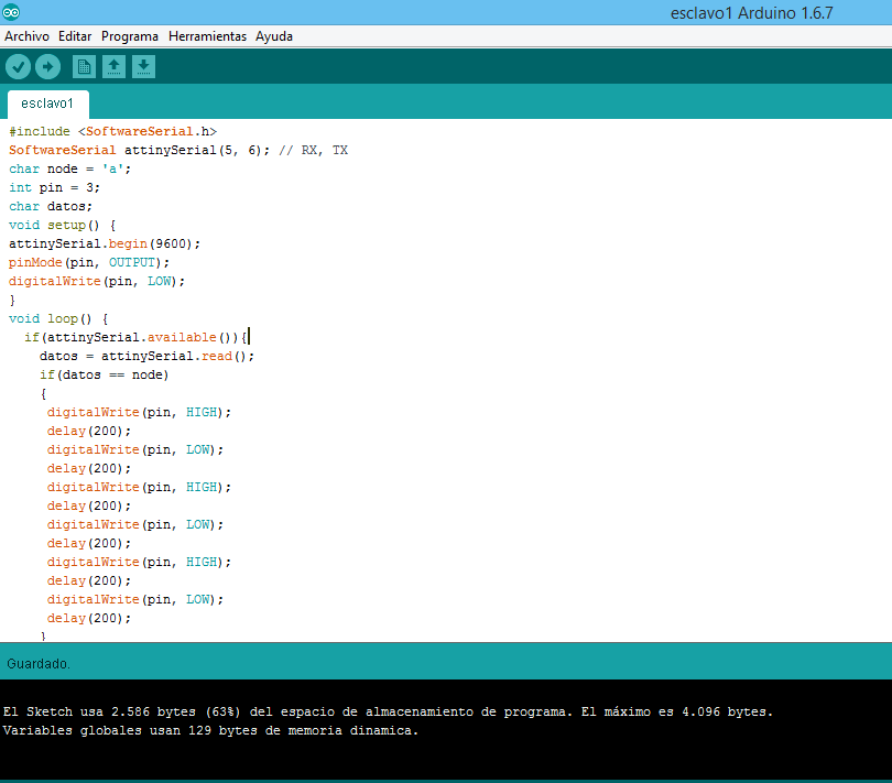
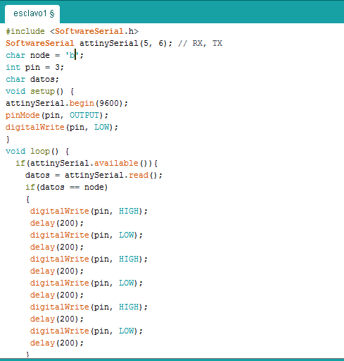
The logic is the next. I send a node name with the Arduino Serial Monitor, and the slaves listen to it and if the node name is the right one, they answer blinking. First node is called 'a' and second 'b'. Here I show the pictures of the programming.