
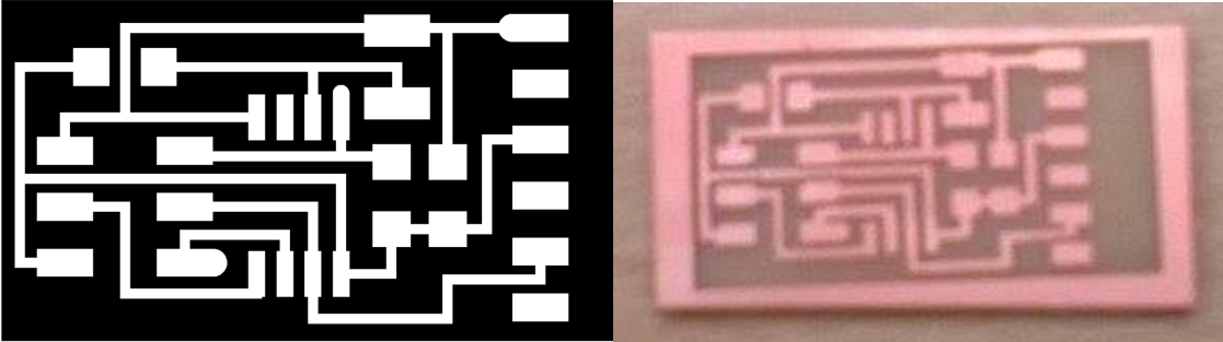
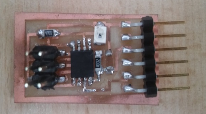
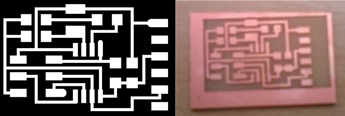
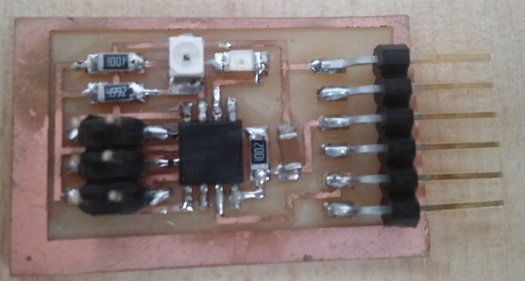
For this assignment the design of "Light", which consists of the completion of two plates, one of which is phototransistor, was chosen whose implementation was as follows:
Description:
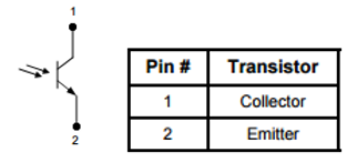
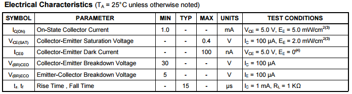
The OP580 is an NPN silicon phototransistor mounted in a miniature SMD package. The device has a flat window lens, which enables a wide acceptance angle. It is packaged in a plastic leadless chip carrier that is compatible with most automated mounting equipment. The OP580 is mechanically and spectrally matched to the OP280 infrared LED.
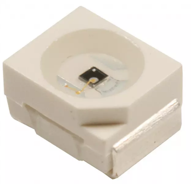
Consideraciones que se debe de tomar al momento de soldar este componente:
Notes:
1. Solder time less than 5 seconds at temperature extreme.
2. To calculate typical collector dark current in µA, use the formula ICEO = 10(0.04 Ta-3.4) where Ta is the ambient temperature in ° C.
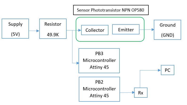
La conexión del sensor al microcontrolador se encuentra de la siguiente manera:
Microcontroller Attiny 45
Este microcontrolador tiene las siguientes características
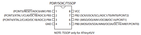
Port B (PB5:PB0)
Port B is a 6-bit bi-directional I/O port with internal pull-up resistors (selected for each bit). The Port B output buffers have symmetrical drive characteristics with both high sink and source capability. As inputs, Port B pins that are externally pulled low will source current if the pull-up resistors are activated. The Port B pins are tri-stated when a reset condition becomes active, even if the clock is not running.
En este caso se está usando el PB3 del microcontrolador para la recepción directa de los datos, este pin puede trabajar como un ADC, el cual recibe los datos de manera analógica.
Además se está usando el PB2 para el envío de los datos hacia la PC.
Microcontroller Datasheet
http://www.atmel.com/images/atmel-2586-avr-8-bit-microcontroller-attiny25-attiny45-attiny85_datasheet.pdf
Luego de comprender la conexión de la target se debe de realizar la programación
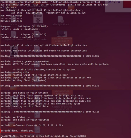
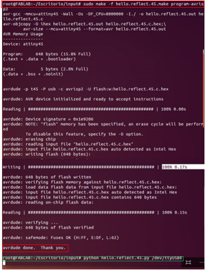
Then it should run the following commands once connected the board
To program the microcontroller

Then we wait for the confirmation message
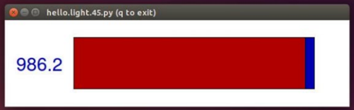
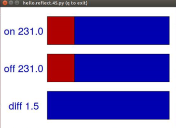
Then it should run the Python program using the following code

Finally the program is as follows
Video
Then it should run the following commands once connected the board
To program the microcontroller

Then we wait for the confirmation message
Then it should run the Python program using the following code

Finally the program is as follows
Video
CONCLUSIONS
This task was very interesting in the application and use of the sensors since they receive information input and processed for the execution of any activity in this case was the change in light intensity.