Exercise 15 Networking and Communications
Requirement
- design, and
- build a wired &/or wireless network connecting at least two processors
Introduction
So far in this course, we have been making PCB boards to each do something on its own, whether input or output or using it as an ISP. This week, we learn how to build a network using 2 or more boards, to have them talk to one another. This week's lesson is going to be quite helpful for me to learn how to communicate with more than one microcontroller.
Below are some of the different methods of networking and communication discussed in class:
- Synchronous serial communication
- Asynchronous serial communication
- I2C
- Serial Peripheral Interface (SPI)
Synchronous serial communication
A synchronous serial interface always pairs its data line(s) with a clock signal, so all devices on a synchronous serial bus share a common clock. This makes for a more straightforward, often faster serial transfer, but it also requires at least one extra wire between communicating devices. Examples of synchronous interfaces include SPI, and I2C.
Asynchronous serial communication
Asynchronous serial communication is a form of serial communication in which the communicating endpoints' interfaces are not continuously synchronized by a common clock signal. Data is transferred without support from an external clock signal. Instead of a common synchronization signal, the data stream contains synchronization information in form of start and stop signals, before and after each unit of transmission, respectively. The start signal prepares the receiver for arrival of data and the stop signal resets its state to enable triggering of a new sequence. Both sides must also agree on the transmission speed (such as 9600 bits per second) in advance.
I2C
The I2C bus is a half-duplex, synchronous, multi-master bus requiring only two signal wires: data (SDA) and clock (SCL). These lines are pulled high via pull-up resistors and controlled by the hardware via open-drain drivers, giving a wired-AND interface. I2C uses an addressable communications protocol that allows the master to communicate with individual slaves using a 7-bit or 10-bit address. During communication with slave devices, the master generates all clock signals for both communication to and from the slave. Each communication begins with the master generating a start condition, an 8-bit data word, an acknowledge bit, followed by a stop condition or a repeated start. Each data bit transition takes place while SCL is low, except for the start and stop conditions. The start condition is a high-to-low transition of the SDA line while the SCL line is high. A stop condition is a low-to-high transition of the SDA line while the SCL line is high. The acknowledge bit is generated by the receiver of the message by pulling the SDA line low while the master releases the line and allows it to float high. If the master reads the acknowledge bit as high, it should consider the last communication word not received and take appropriate action, including possibly resending the data.
Serial Peripheral Interface (SPI)
Serial Peripheral Interface (SPI) is an interface bus commonly used to send data between microcontrollers and small peripherals such as shift registers, sensors, and SD cards. It uses separate clock and data lines, along with a select line to choose the device you wish to talk to. It uses separate lines for data and a “clock” that keeps both sides in perfect sync. The clock is an oscillating signal that tells the receiver exactly when to sample the bits on the data line. This could be the rising (low to high) or falling (high to low) edge of the clock signal; the datasheet will specify which one to use. When the receiver detects that edge, it will immediately look at the data line to read the next bit. Because the clock is sent along with the data, specifying the speed isn’t important, although devices will have a top speed at which they can operate.
The SPI bus consists of four signals: master out slave in (MOSI), master in slave out (MISO), serial clock (SCK), and active-low slave select (/SS). As a multi-master/slave protocol, communications between the master and selected slave use the unidirectional MISO and MOSI lines, to achieve data rates over 1Mbps in full duplex mode. The data is clocked simultaneously into the slave and master based on SCK pulses the master supplies. Only one side generates the clock signal (usually called CLK or SCK for Serial ClocK). The side that generates the clock is called the “master”, and the other side is called the “slave”. There is always only one master (which is almost always your microcontroller), but there can be multiple slaves (more on this in a bit). When data is sent from the master to a slave, it is sent on MOSI data line. If the slave needs to send a response back to the master, the master will continue to generate a prearranged number of clock cycles, and the slave will put the data onto the MISO data line. A disadvantage to SPI is the requirement to have separate /SS lines for each slave. Provided that extra I/O pins are available, or extra board space for a demultiplexer IC, this is not a problem. But for small, low-pin-count microcontrollers, a multi-slave SPI interface might not be a viable solution.
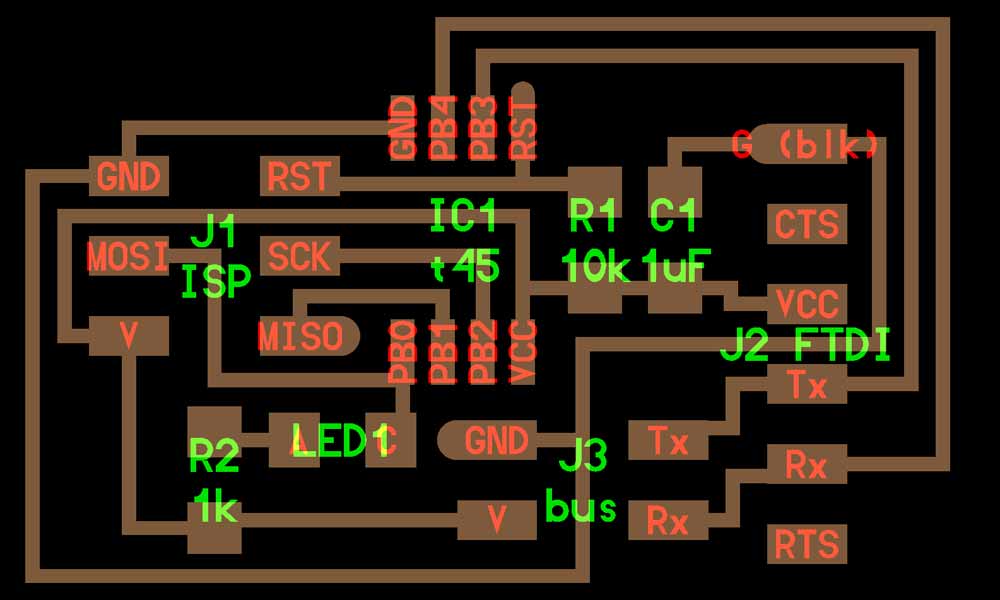
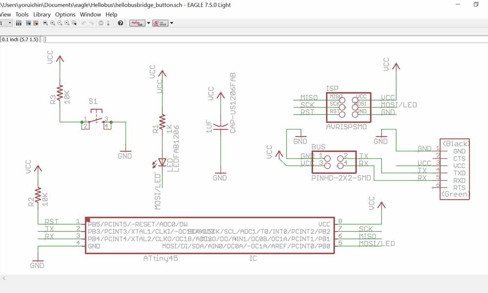
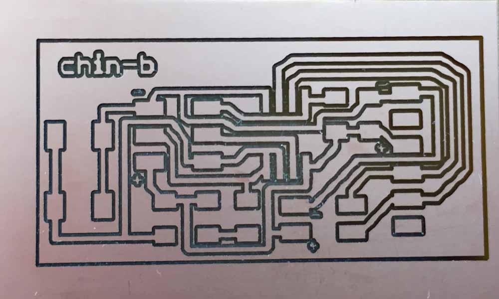
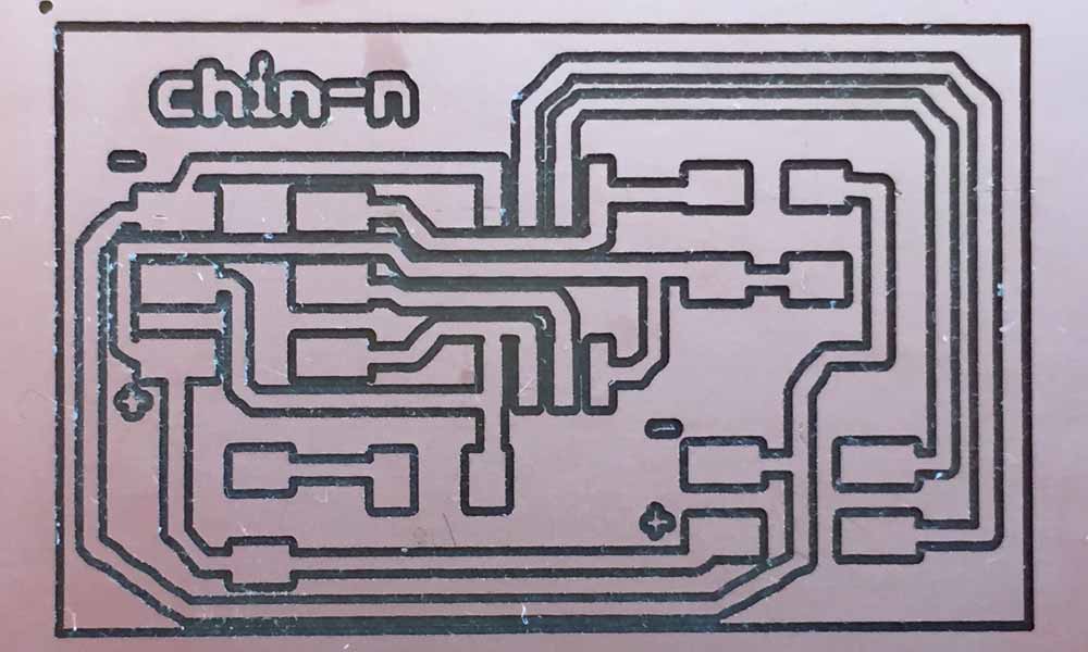
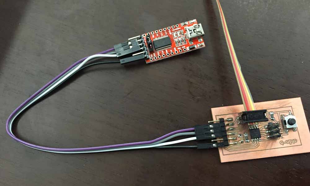
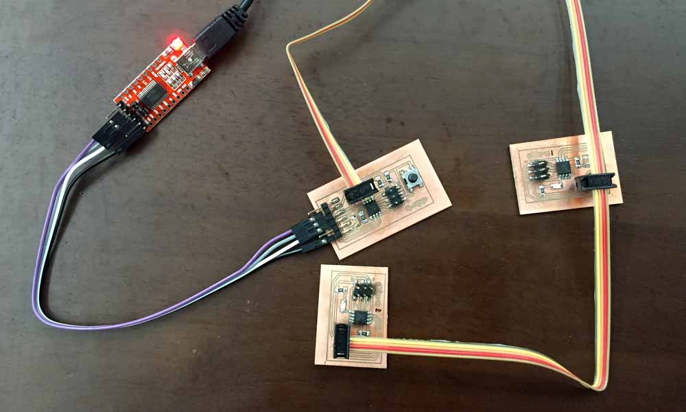
Designing the asynchronous serial communication boards
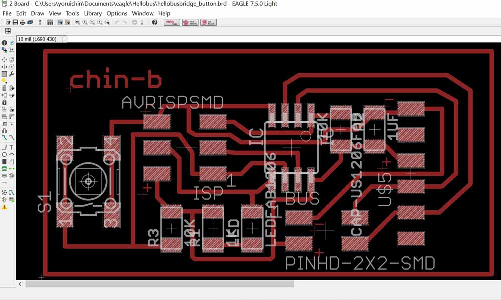
I will be attempting to build an asynchronous serial communication network, making 3 boards (one bridge and 2 nodes) to communicate with the computer via a FTDI interface. I would be referring to Neil's boards in my design, making attempts to add a button to the bridge board, which I think might come in handy for my final project.
Components needed
- 1 x BRIDGE:
- 1 x ATTINY85
- 1 x 3X2 PIN HEADER (ARVISP SMD)
- 1 x 2X2 PIN HEADER SMD
- 1 x 1X6 FTDI SMD HEADER
- 1 x CAPACITOR 1 uf
- 1 x 10 k Ohm RESISTOR RES-US1206FAB
- 1 x LED 1206 smd
- 1 x 1 k Ohm RESISTOR RES-US1206FAB
- 1 x OMRON SWITCH
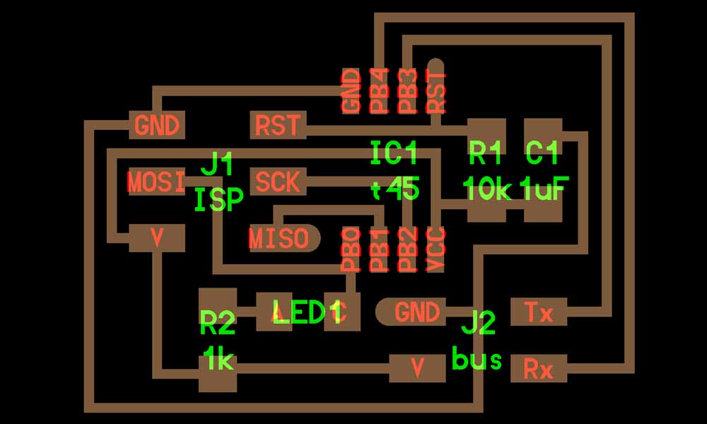
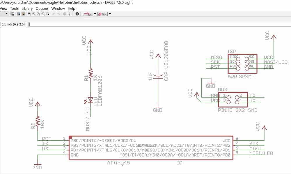
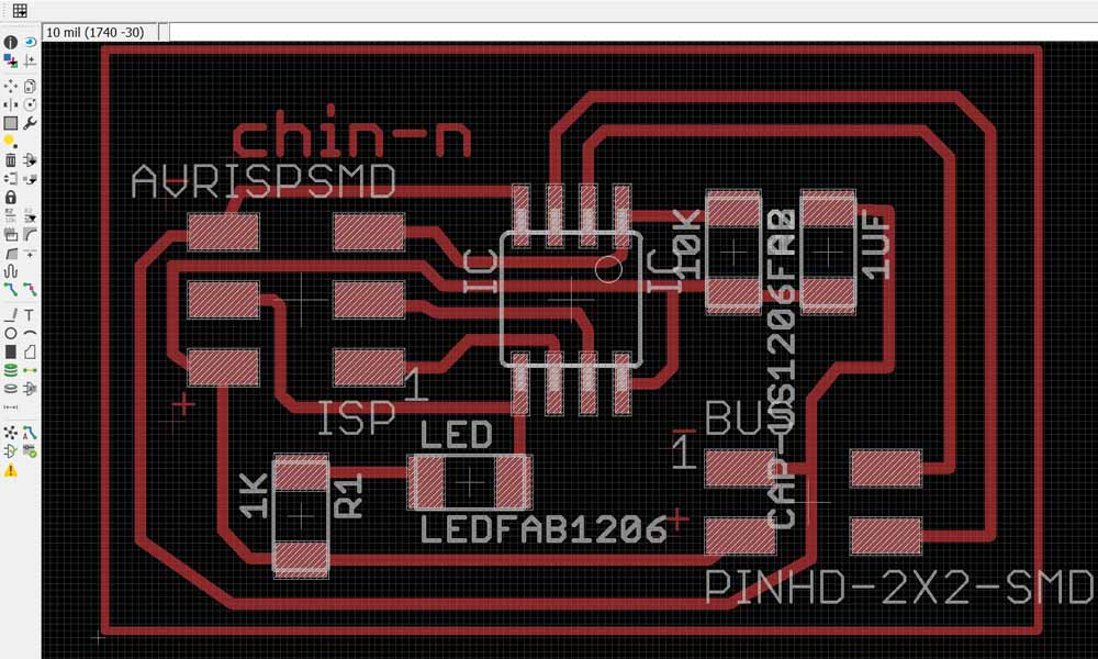
- 2 x NODES:
- 2 x ATTINY45
- 2 x 3X2 PIN HEADER (ARVISP SMD)
- 2 x 2X2 PIN HEADER SMD
- 2 x CAPACITOR 1 uf
- 2 x 10 k Ohm RESISTOR RES-US1206FAB
- 2 x LED 1206 smd
- 2 x 1 k Ohm RESISTOR RES-US1206FAB
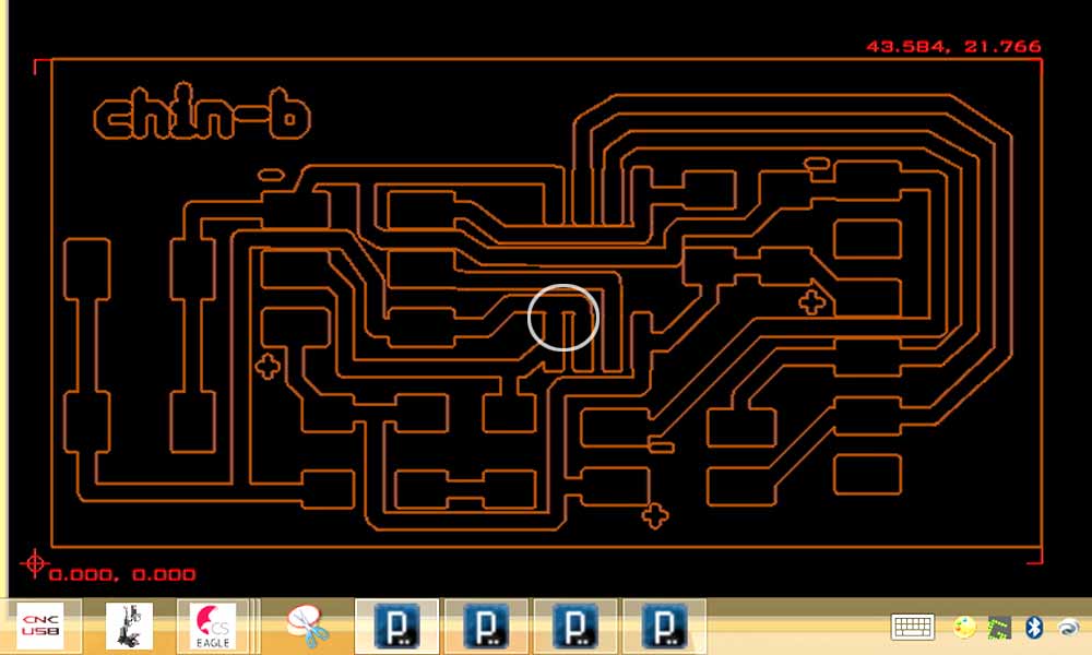
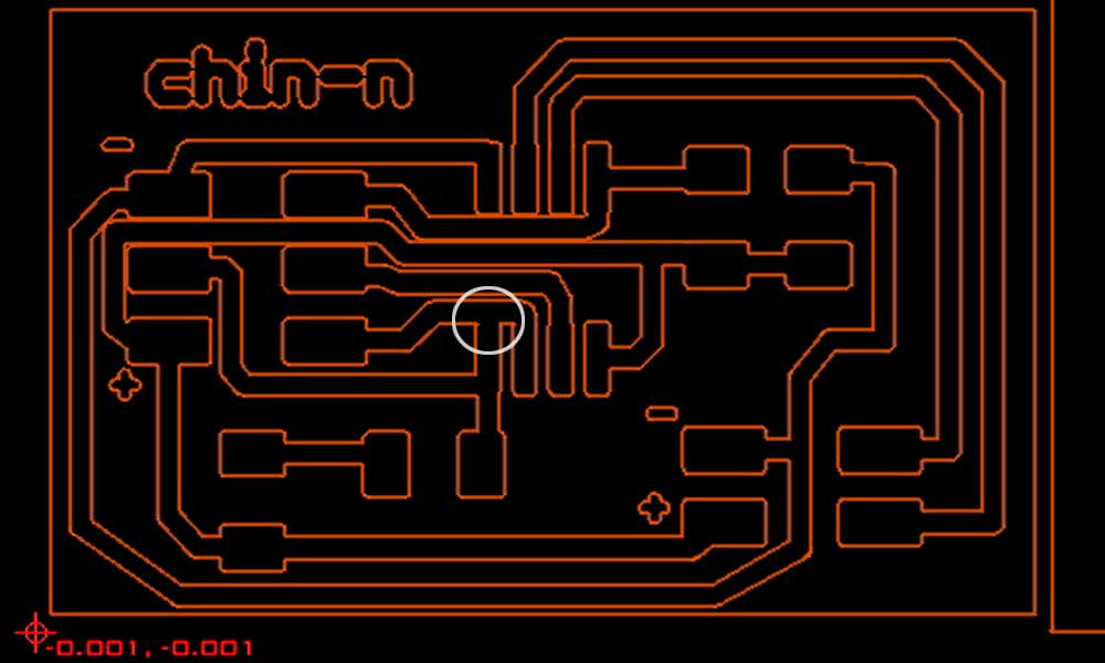
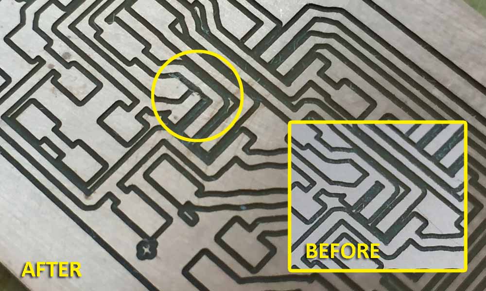
Short-circuited Traces
I converted the eagle file to G-code to be milled by the PCB2020B CNC Router. Details of the milling process has been documented in week 6. I did not realize one of my traces was too near to the pad of the microchip until it has been milled. I only found out when I tried to stuff the components onto the board. The board has a shorted path (circled portion). I have considered changing the width of the traces running through my ATtiny45 from 16mil to 12mil and re-mill the boards. But because the milling bit was blunt, I wasn't successful in my re-mill. At this moment, I remembered the lab purchased a new ultrasonic cutter which might just do the trick! At 40,000 ultrasonic vibrations per second, the ZO-41PLUS ultrasonic cutter cuts at a non-audible sound, reducing the friction during the cutting process. It worked like a charm and I was able to use those boards for my assignment.

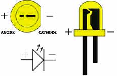
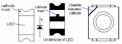
Polarity of LED
For my own reference, I have included in my documentation, the symbols that indicate polarity of LEDs:

Programming the ATtiny45
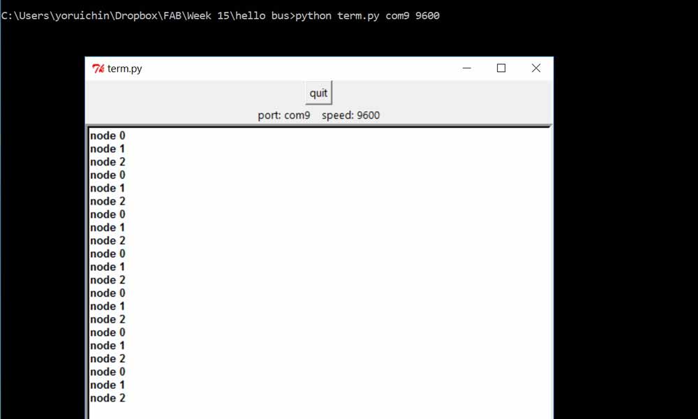
Below is a list of the important commands I used in the command prompt:
  1.    cp "C:\Users\yoruichin\Dropbox\FAB\Week 15\hello bus\ccode\hello.bus.45.make" makefile  // "makefile" will be generated

  2.    make    // 2 files will be generated, *.out and *.hex

  3.    avrdude -P com4 -c stk500v1 -b 19200 -p t45 -U flash:w:hello.bus.45-b.c.hex   // flash the ATtiny45

  4.    python term.py com9 9600  // com9 is my FTDI serial interface and 9600 is the transmission speed
Because I was using different file name for the bridge and nodes, I have made the following amendments to my make file to accommodate this change, removing the "#" sign next to the line of the board I am flashing.
hello.bus.45.make#PROJECT=hello.bus.45-b #PROJECT=hello.bus.45-n1 #PROJECT=hello.bus.45-n2 SOURCES=$(PROJECT).c
Details on Programming the firmware with WinAVR has been documented in week 13 and details on setting up the environment for executing python codes has been documented in week 9. I was able to make small changes to the programme to make the LED flash 3 times when I press the number corresponding to the node id.
Reflections
I'm glad I was able to build upon previous knowledge on WinAVR to flash the microchip and successfully met the requirements for this week's assignment. However, I wished I could do more than making the LEDs blink 3 times. I stuffed in a button but had no time to do anything with the button. It was also partly due to a lack of understanding of C language. I need to understand c language a bit more deeply so that I can better manipulate the codes to do more complex stuff.
Download work files
- hello.bus.45-b.c
- hello.bus.45-n1.c
- hello.bus.45-n2.c
- hellobusbridge_button.sch
- hellobusbridge_button.brd
- hellobusnode.sch
- hellobusnode.brd
References
- Asynchronous serial communication
- How I2C Communication Works and How To Use It with Arduino
- Serial Protocols Compared
- Serial Communication
- Serial Peripheral Interface (SPI)
- I2C
- 11B. Serial Communications: I2C and SPI