What is Computer Aided Design
Computer-aided design (CAD) is the use of computer systems to aid in the creation, modification, analysis, or optimization of a design. CAD software is used to increase the productivity of the designer, improve the quality of design, improve communications through documentation, and to create a database for manufacturing. CAD output is often in the form of electronic files for print, machining, or other manufacturing operations.
Computer-aided design is used in many fields. Its use in designing electronic systems is known as electronic design automation, or EDA. In mechanical design it is known as mechanical design automation (MDA) or computer-aided design (CAD), which includes the process of creating a technical drawing with the use of computer software.
CAD software for mechanical design uses either vector-based graphics to depict the objects of traditional drafting, or may also produce raster graphics showing the overall appearance of designed objects. However, it involves more than just shapes. As in the manual drafting of technical and engineering drawings, the output of CAD must convey information, such as materials, processes, dimensions, and tolerances, according to application-specific conventions.
Trying some software!
On Neil's class he introduced a lot. I spent some time to try some of the software looks beautiful:)
GIMP
GIMP (an acronym for GNU Image Manipulation Program) is a free and open-source raster graphics editor used for image retouching and editing, free-form drawing, resizing, cropping, photo-montages, converting between different image formats, and more specialized tasks.
GIMP is easy to use but limited in function. Like PAINT in Windows, GIMP is just little bit powerful than it.
Inkscape
Inkscape is a free and open-source vector graphics editor; it can be used to create or edit vector graphics such as illustrations, diagrams, line arts, charts, logos and complex paintings. Inkscape's primary vector graphics format is Scalable Vector Graphics (SVG) version 1.1. While Inkscape can import and export several formats, all editing workflow inevitably occur within the constraints of the SVG format.
Inkscape is a little bit harder for me. But it is powerful. In my color box project, I was thinking not to use box but something else. As a starwar's fan, I draw two light saber with Inkscape. As is shown below. When we put two saber together, It will change to another color.
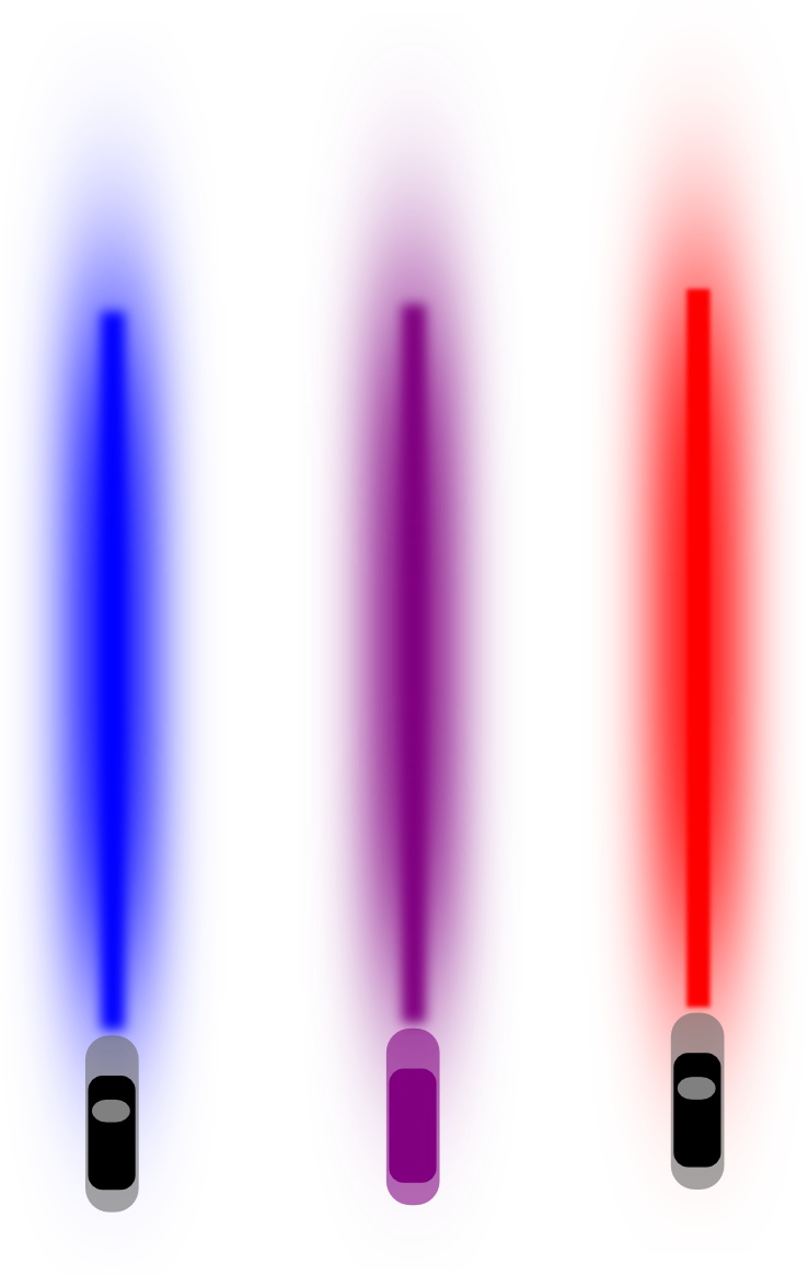
*I draw the picture in Inkscape but I can only save it as a picture file. I am not sure what is 2D design files..
But I dropped this idea quickily. Because the box can be set as many as you want, but the saber...Only the JEDI has one.
123D
Autodesk 123D is a suite of hobbyist CAD and 3D modelling tools created by Autodesk. It is similar in scope to Trimble SketchUp and is based on Autodesk's Autodesk Inventor. As well as the more basic drawing and modelling capabilities it also has assembly and constraint support and STL export. Available for the software is also a library of ready-made blocks and objects.
123D is easy to use. Based on merging, just click and pull the shape and get your 3D design work.
TinkerCAD
TinkerCAD is the easiest tools i have ever used. All you need to do is put the box together. I think it is a wonderful tool for k12 education.
Blender
Blender is a professional free and open-source 3D computer graphics software product used for creating animated films, visual effects, art, 3D printed models, interactive 3D applications and video games. Blender's features include 3D modeling, UV unwrapping, texturing, raster graphics editing, rigging and skinning, fluid and smoke simulation, particle simulation, soft body simulation, sculpting, animating, match moving, camera tracking, rendering, video editing and compositing. Alongside the modeling features it also has an integrated game engine.
I don't know why, but Blender is very hard for me. I even don't know how the tool bar work after two hours' learning. Luckily, my local tutor Anders intruduced me another 3D design software that I can handle easily -- Fusion 360.
Fusion 360
In fusion 360, you make changes on surfaces and combine 2D design with 3D design. And the T-sample tools is very much like Rhino. But Rhino is very expensive, Fusion 360 is free for educational use. I use fusion 360 to draw a bottle and made it like a real bottle.
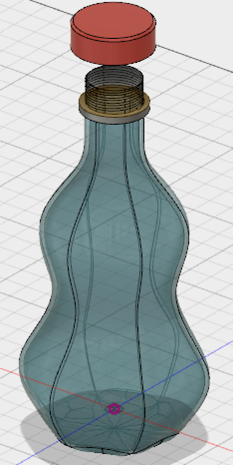
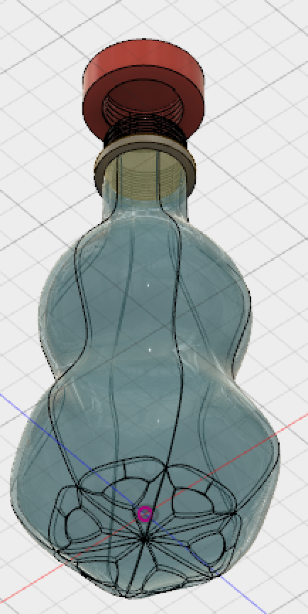
The steps to make this bottle are as follows:
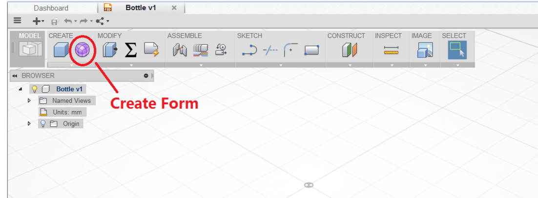
First, create a design, automatically entered into the parametric modeling environment. Characterized by a window at the bottom there is a timeline, used to record the history of modeling.
Click "Create Form" command on the toolbar, go to T-spline environment for bottle design. Button on the toolbar to display commands related to T-spline, while on the timeline will generate a node.
The far right of the toolbar "Finish Form" that can be used to return to the earlier modeling environment, this button can also help identify the current user group environment.
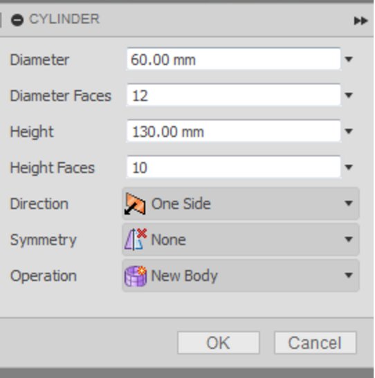
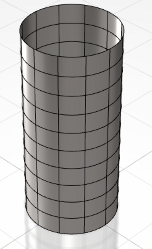
Click "Create -> cylinder", click XZ coordinate plane, create a T-spline cylinder. Parameters are as follows. T is a feature spline modeling is from simple to complex, from the basic form began.
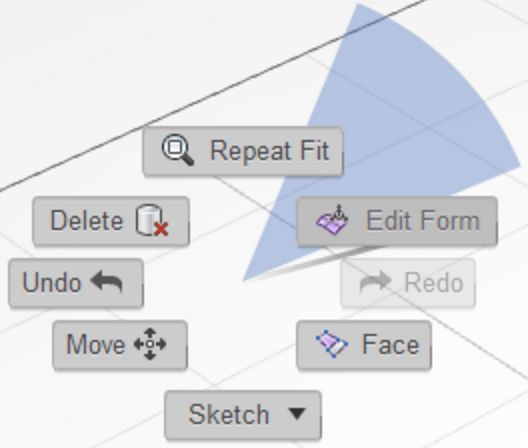
Next, we use the "Edit form (Edit Form)" command to adjust the shape of the bottle. On T-spline modeling, the high frequency of use of this command, so Fusion 360 put it easily accessible context menu. In addition, the start command will display tips and tricks for the command in the lower right corner, it is very thoughtful UI design.
After starting the command, "Right" click on the top right corner of the small box (View Cube) is switched to the right perspective view of the bottle so that the side facing the user.
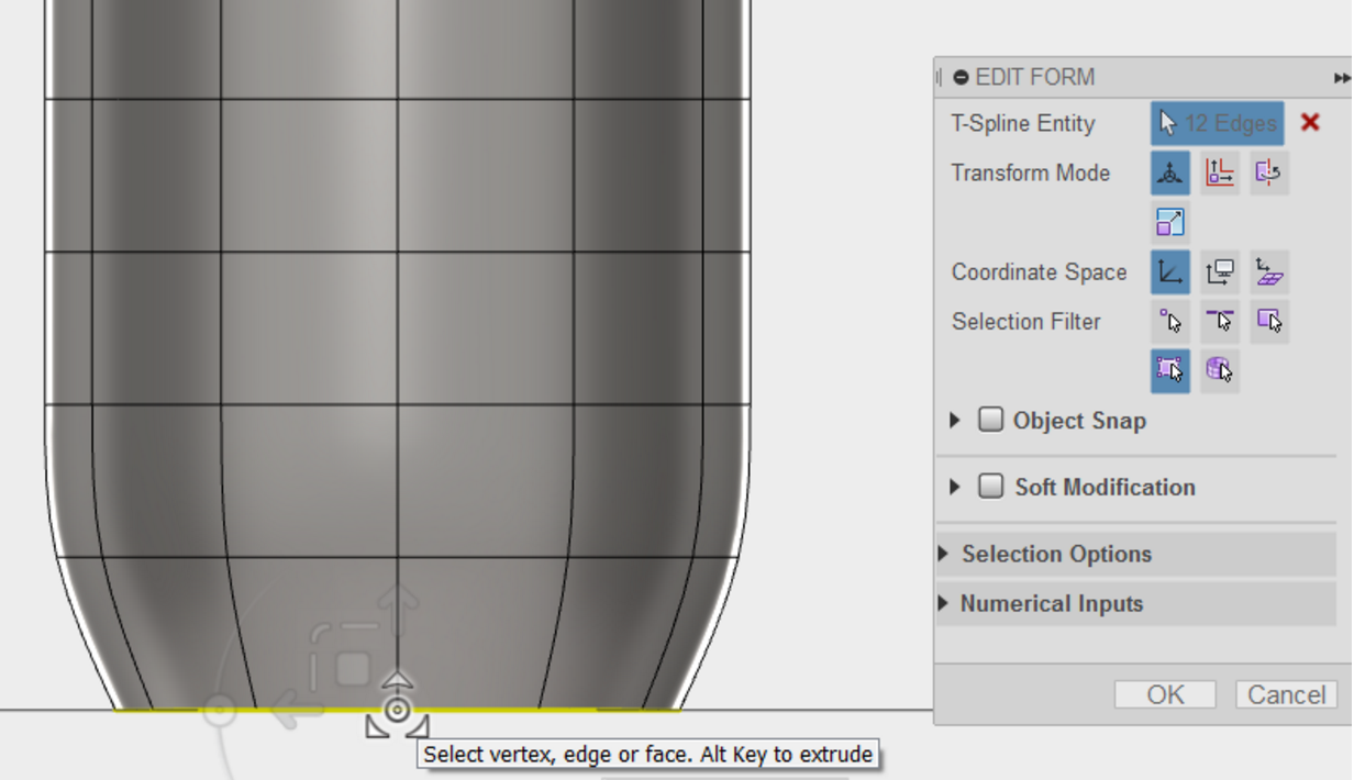
We start with the beginning of the bottom, select the bottom edge of the cylinder circuit (or double-click a marquee at the bottom edge), then drag the manipulator origin zoomed to 0.8. You can see real-time changes at the bottom.
Next, the penultimate layer side circuit scale. Double-click on the penultimate layer of an edge to select the entire circuit, drag the manipulator origin enlarged to 1.1.
Continue to make adjustments for the remaining layers, from the bottom up, layer by layer scaling. The following proportion for reference:
Third from the bottom layer, zoom to 0.9;
Fourth from the bottom layer, scaled to 0.75;
Fifth from the bottom layer, scaled to 0.65;
Countdown sixth floor, scaled to 0.8;
Countdown seventh floor, scaled to 0.9;
Countdown eighth floor, scaled to 0.65;
Countdown ninth floor, scaled to 0.3;
Countdown tenth floor, scaled to 0.3;
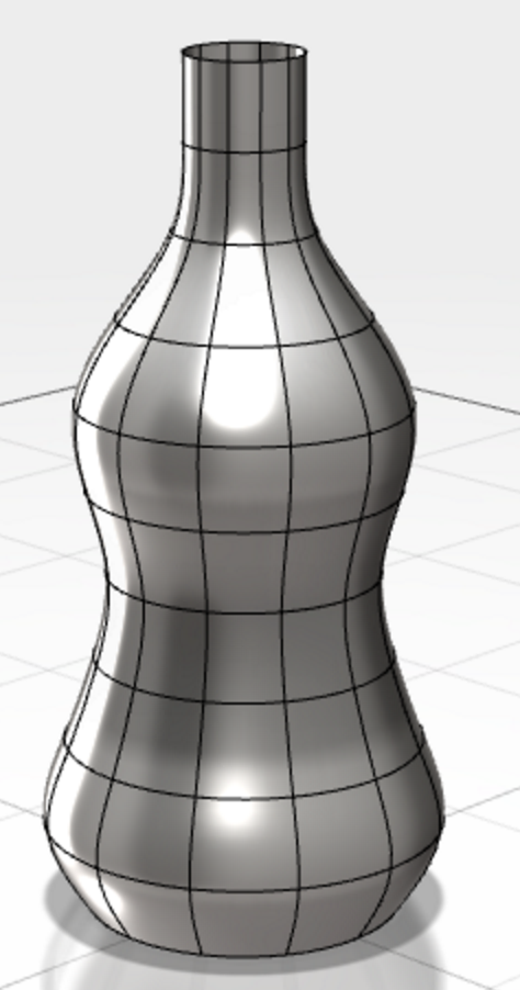
The top layer, scaled to 0.3 to give a shape similar to the following.
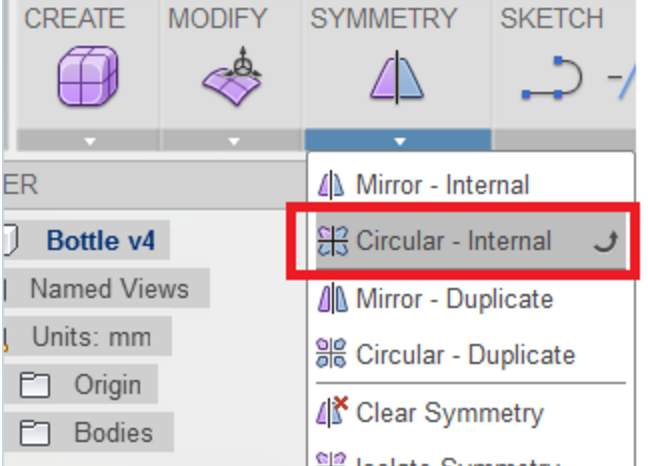
Bottle itself is symmetric, we can call symmetrical ring command (Symmetry-> Circular - Internal) to add a symmetrical relationship. In this case, we modify one, and the rest have a symmetrical change simultaneously.
Select any of the bottle from the bottom side, the program will automatically deduce the possible symmetry and adding numerals. For example, in the following figure, the blue surface is a surface selected, if it continues to choose marked face 4 will create a symmetrical 4 aliquots.
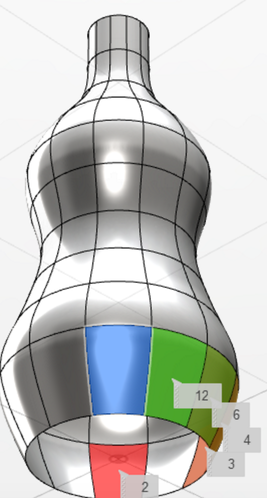
Here, we choose the digital label surface 6, 6 equal portions create symmetry. The model represents a symmetrical relationship with the green line.
Angle switching, back to the right (Right) view.
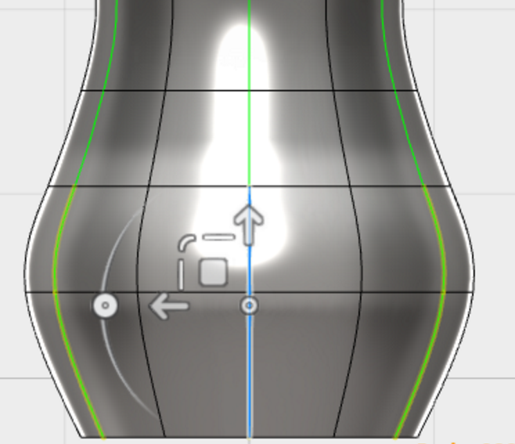
Hold down the Ctrl key and select the two edges shown below, and then call the "Edit form (Edit Form)" command via the context menu.
The two sides still selected, click ViewCube Switch to the Top view (Top).
Drag the manipulator in the opposite direction "down" arrow, the value -6mm. Because the bottle is now annular symmetrical relationship, so the other part of the symmetric synchronize changes.
Next, we use "fill holes (Fill Hole) command to add a bottle bottom.
Choose either side at the bottom, fill the bottom of the form automatically.
Bottle has now begun to take shape, but the bottom is not very stable.
Call the "Edit form (Edit Form)" command, select either the bottom surface.
Switch to the Right view, hold down the Alt key while dragging the manipulator "on" arrow, the value -2mm. Edit Form can hold down the Alt key while dragging to create a new body along a direction, which is very useful tips.
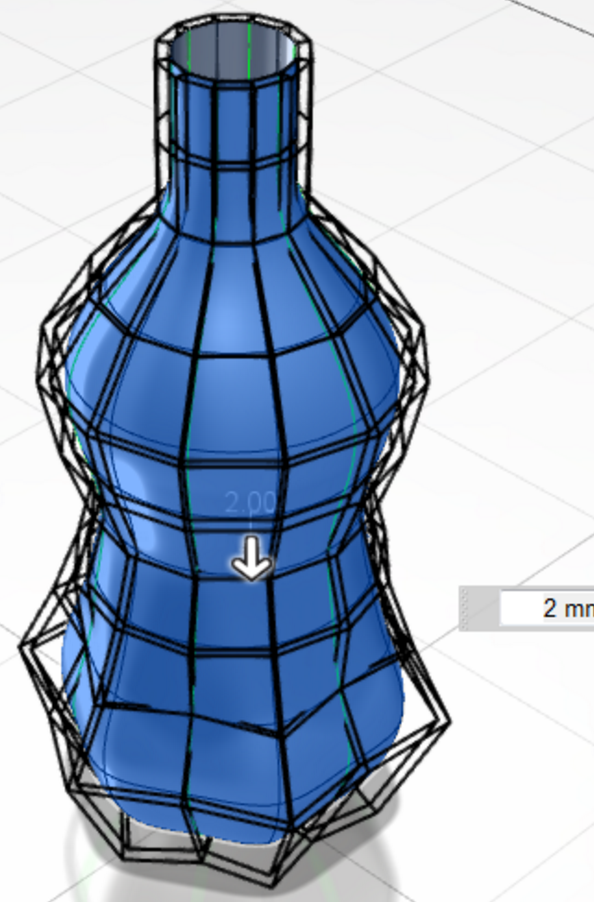
Call "thick (Modify -> Thicken)" command, select the bottle, thickness 2mm, "thick Type" select "soft (Soft)".
Bottle design is complete. Click "Finish Form" to exit the T-spline environment. T-spline modeling results are automatically converted to solid modeling the whole T-spline on the time axis corresponds to a node.
Rhino
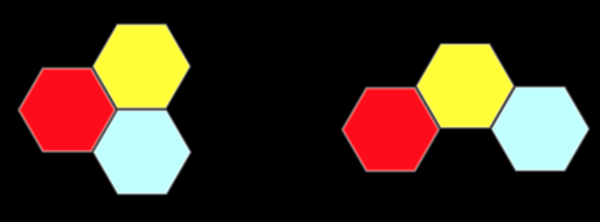
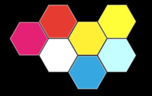
Finally, I use Rhino to build my color box. It's a six-angel box so that I can combine them with many wanys.
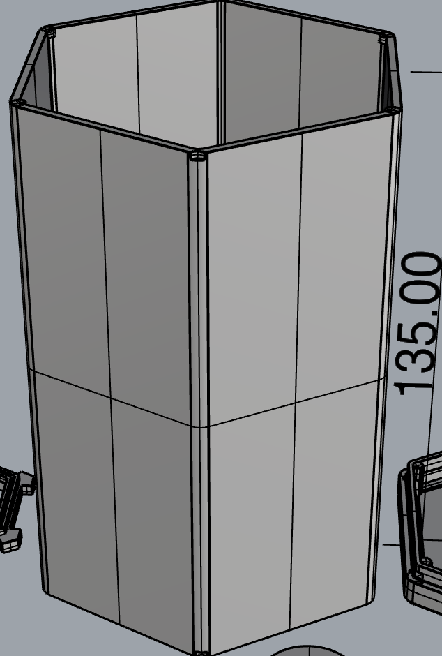
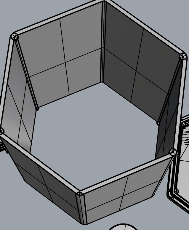
Here is my color box. I use GIMP to draw the picture.We can put three box together, or even more.