Convert .png to .rml
18 Feb
Week4 Electronics Production; milling; SRM; rml
In order for the SRM machine to cut the PCB board, we have to add parameters such as depth, power, speed along with the picture. That's why we have to create a .rml file to deliver the cutting task.
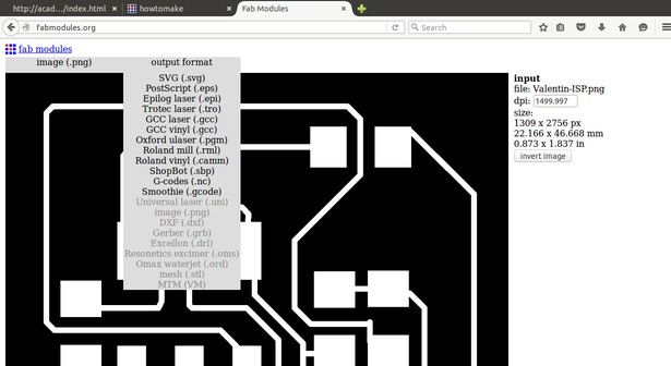
I changed the file format by using fabmodules. Type fabmodules.org in the address bar of the browser, preferably Chrome. Then chose the input format as .png and the output format as .rml. 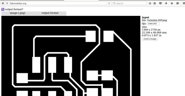
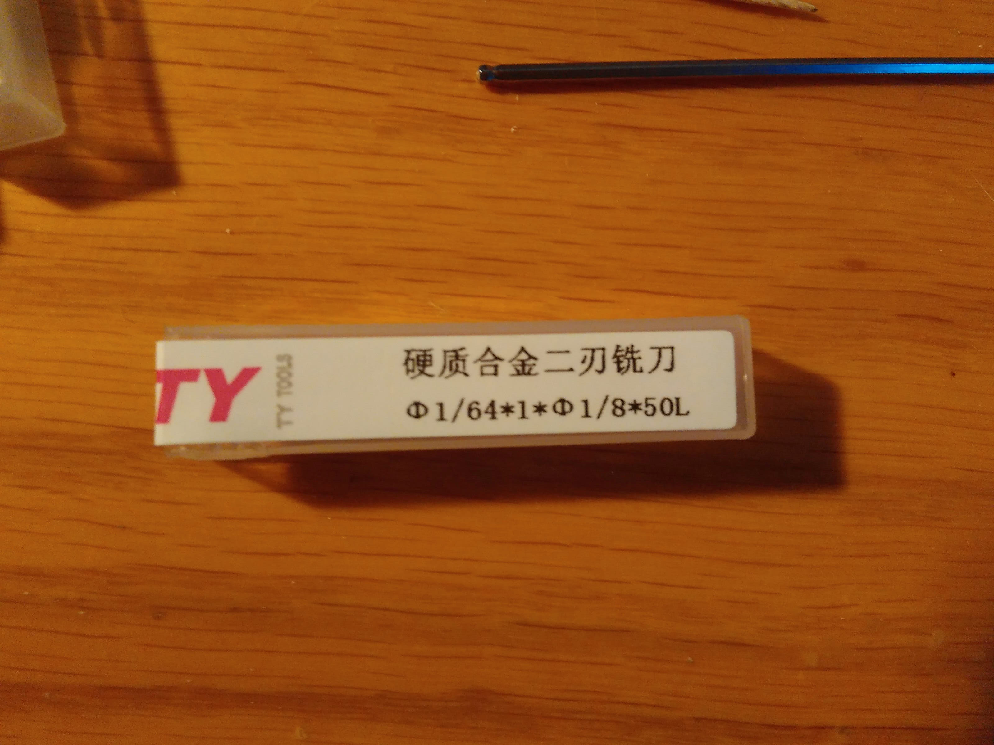
When the 'process' button popped up, chose the tool intended to be used. For the ISP I chose 1/64 and for the cutout I chose 1/32. The rest of the settings would be filled accordingly.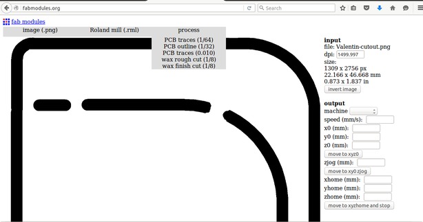
Finally cick on 'calculate' and 'save'.
I used Valentin's design this week. The two rml form of his design can be downloaded here:
Valentin-ISP.rml
Valentin-cutout.rml
Problems
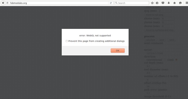
I came across an error message showed below when using firefox browser. No panic when you see this. The file would be saved in the download folder anyway.
Milling PCB with SRM-20
19 Feb
Week4 Electronics Production; milling; SRM
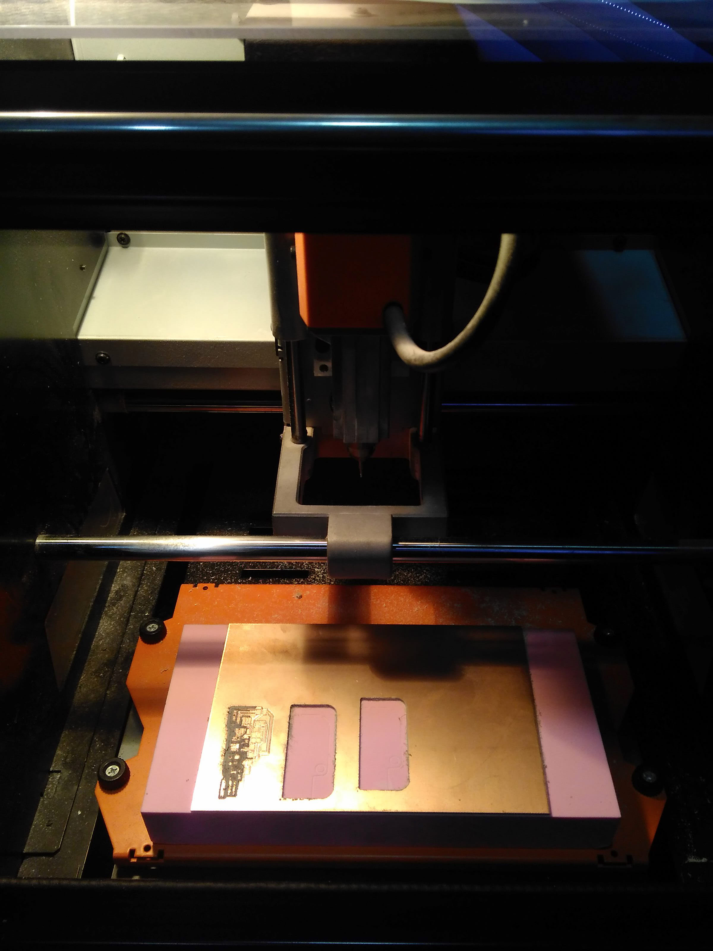
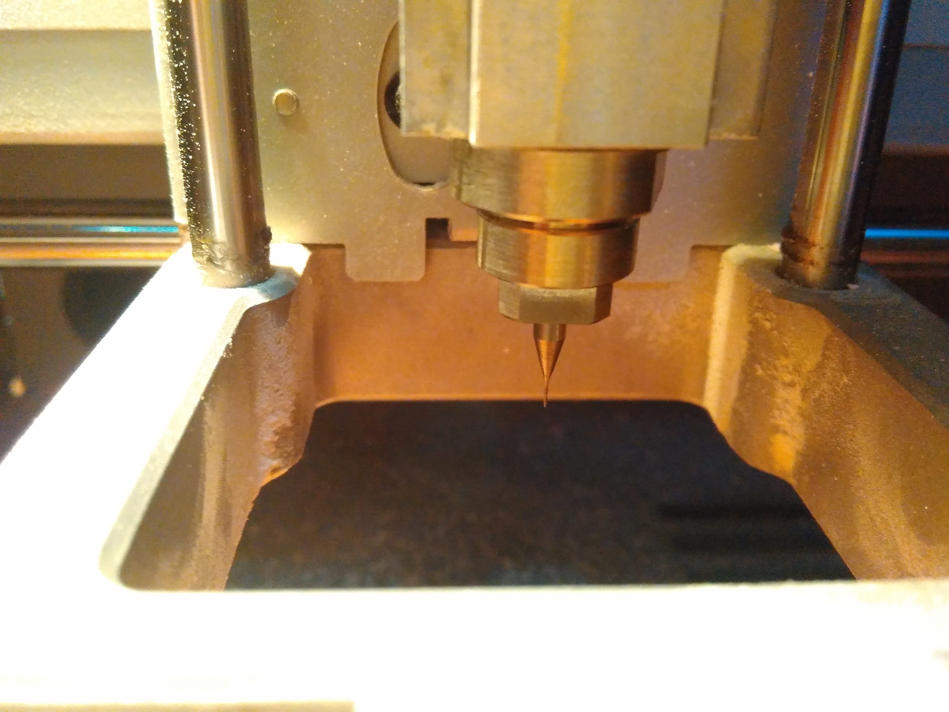
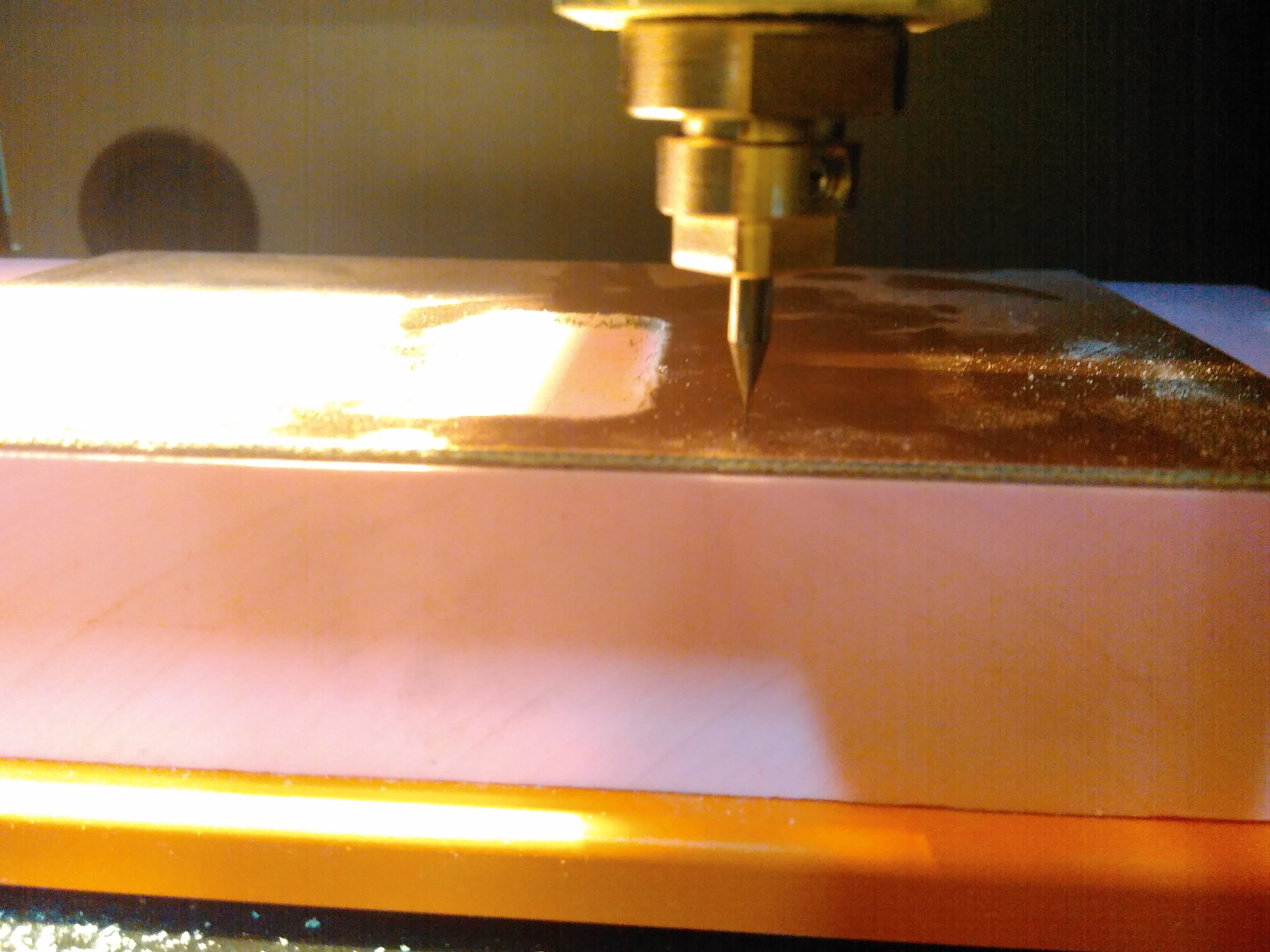
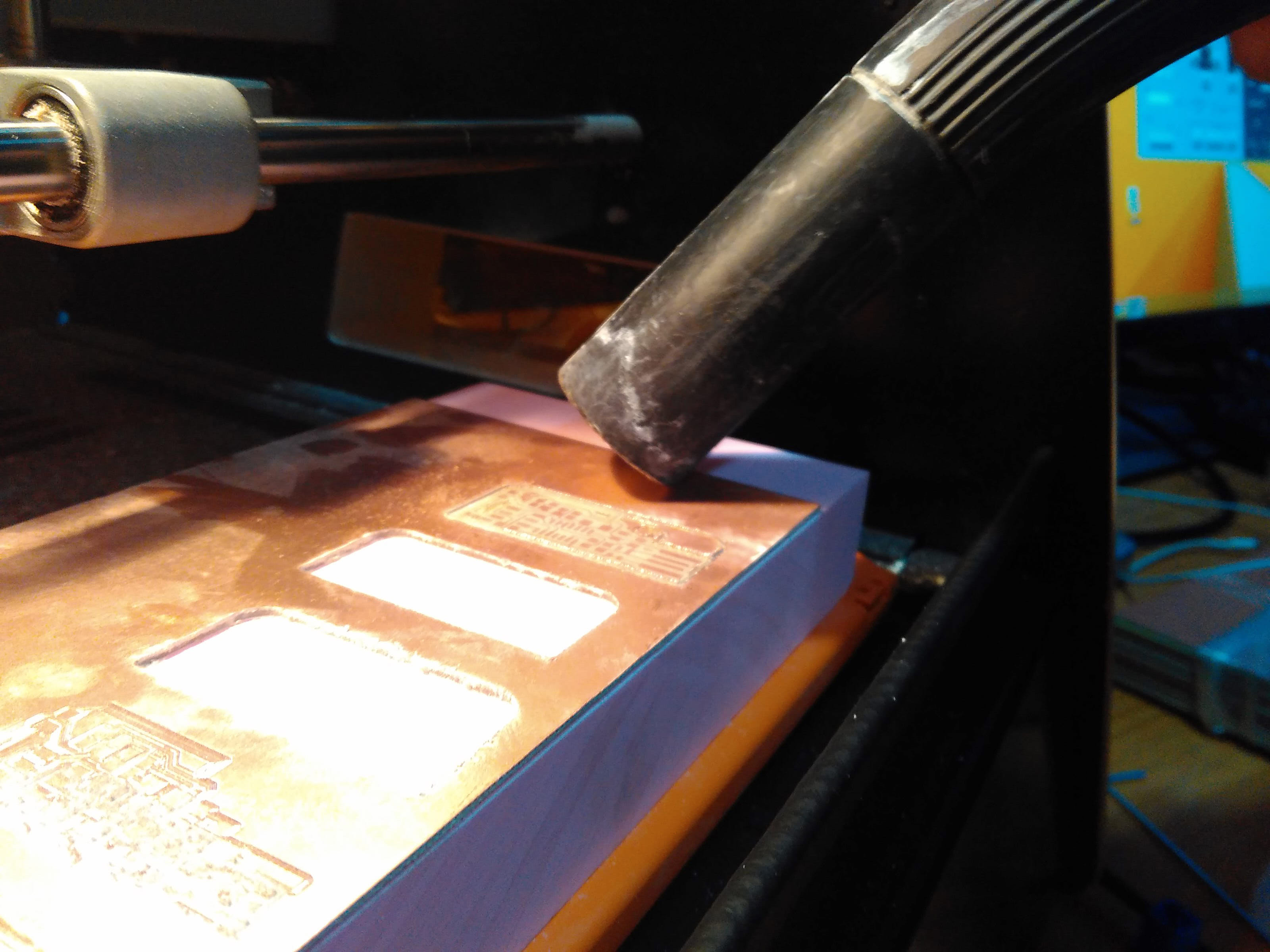
To engrave the circuit first, load the 1/64 cutter to the collet first. Take extra care of head since it's extremely fragile.
Set the original X-Y position. Each option controls for the distance to move over per click.
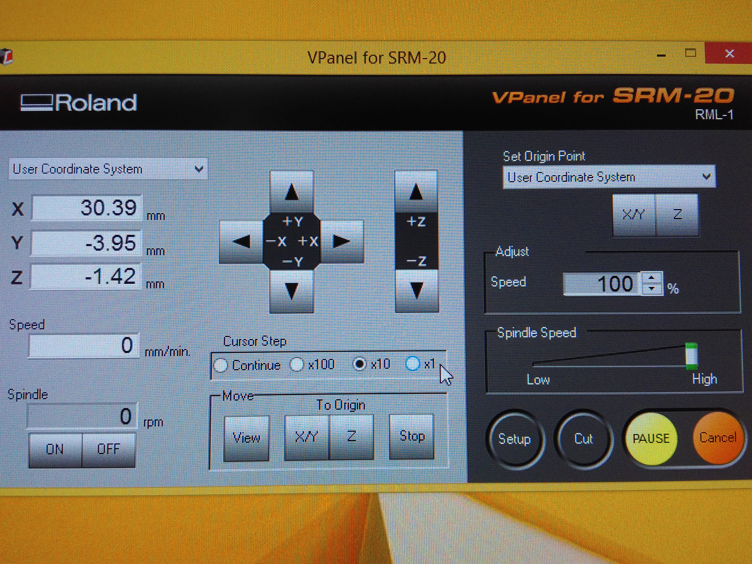
When it comes to the Z axis, leave a gap when pressing down and use a screw to drop the endmill manually so as to avoid smashing the head.
Click on 'X/Y' and 'Z' respectively under Set Origin Point to store the position. *Take down the position details in 'Machine Coordinate System', choose this option from the top-left corner, so that you may find your previous starting point in case you need to redo the work.
When the positioning step is done, click on 'Cut' and add an rml file before pressing 'Output' option.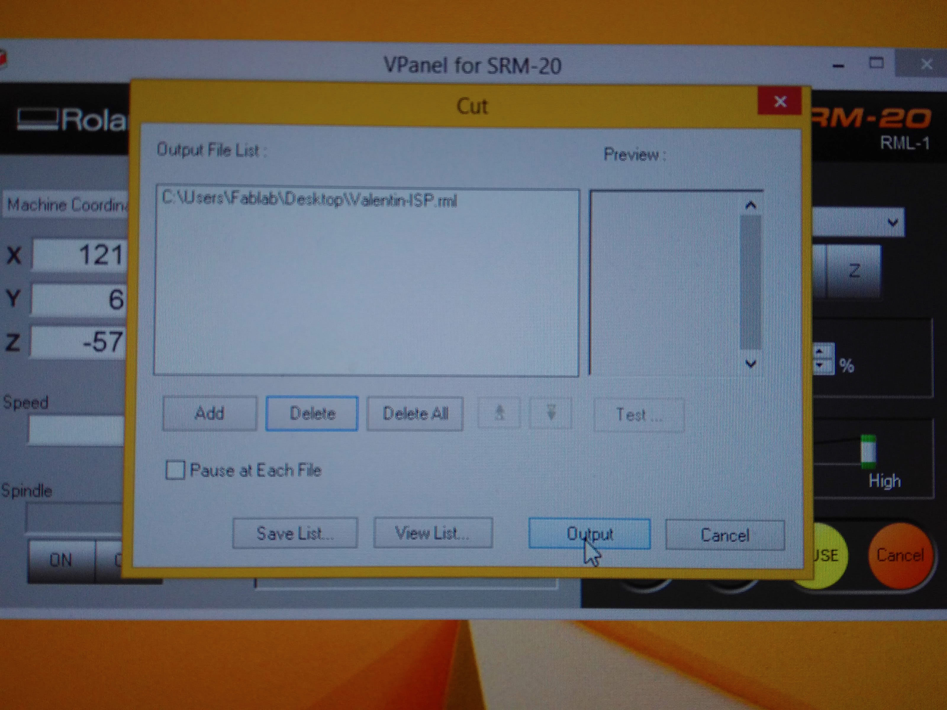
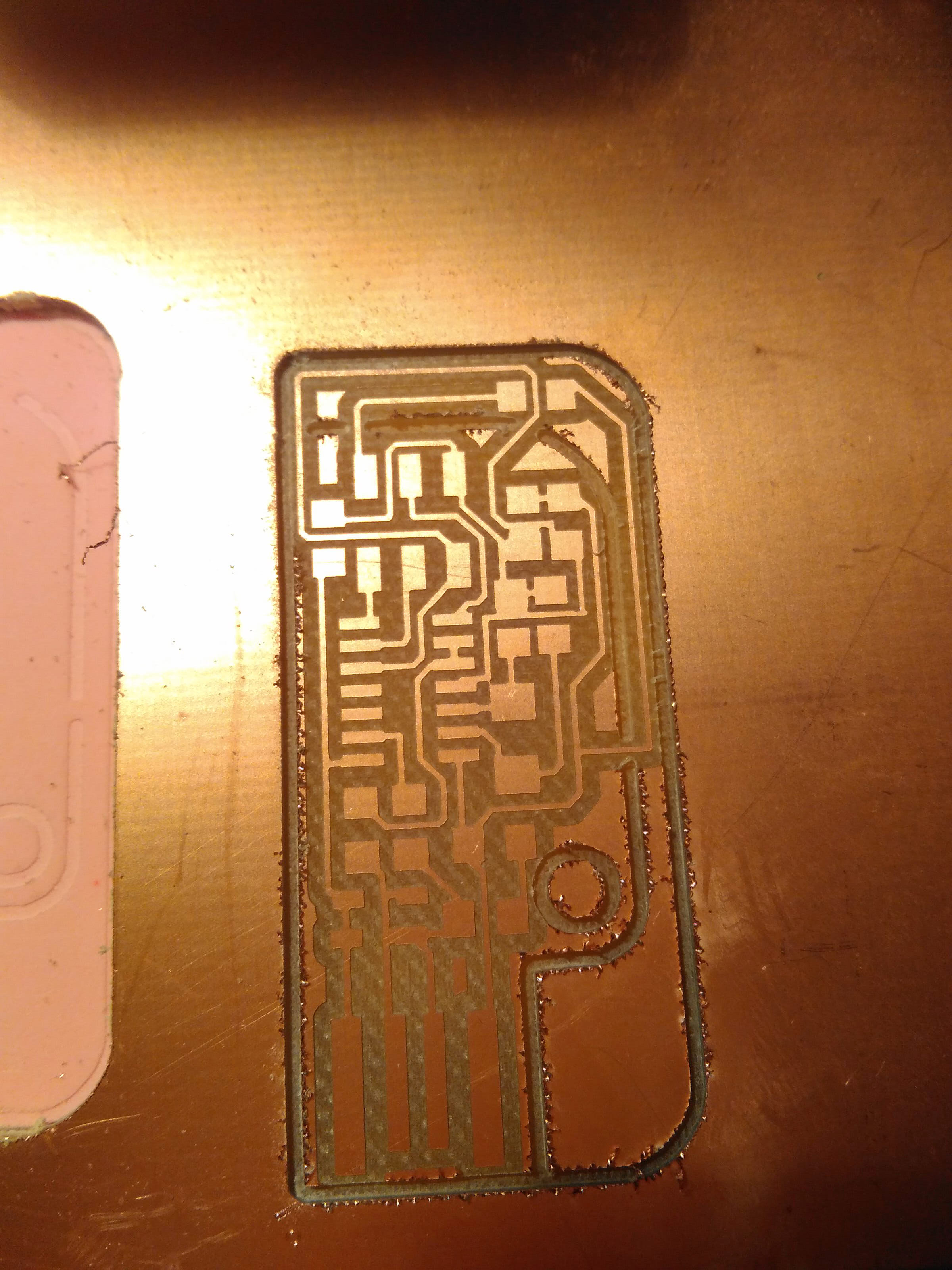
It took about 10 mins for the first task to be done. Click on 'Preview' from the panel to bring the board closer to you.
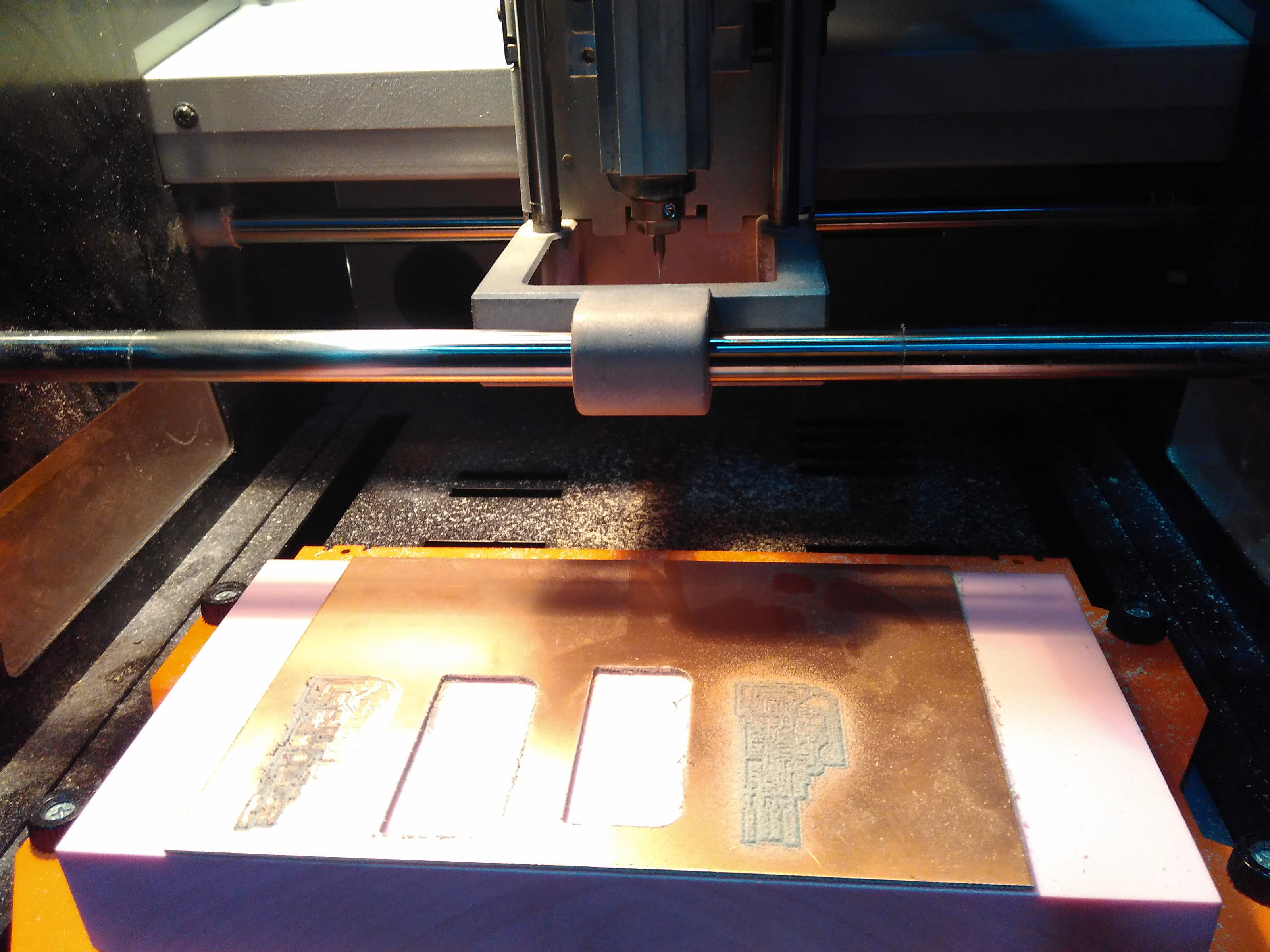
Change a 1/32 inches' endmill and load it to perform the cutting task. Skip the X-Y positioning step but do readjust the Z starting point since it's moved when endmill has been changed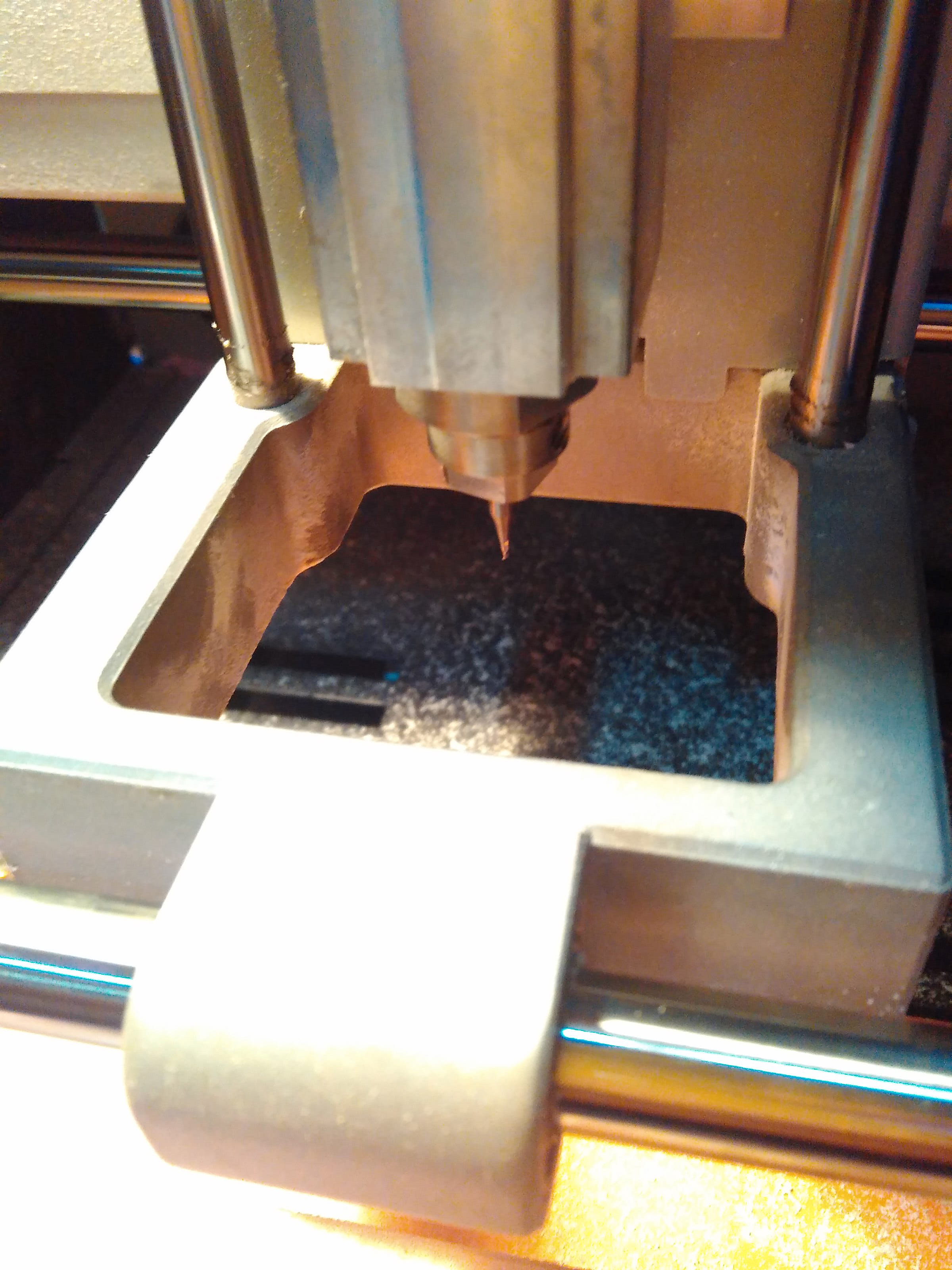
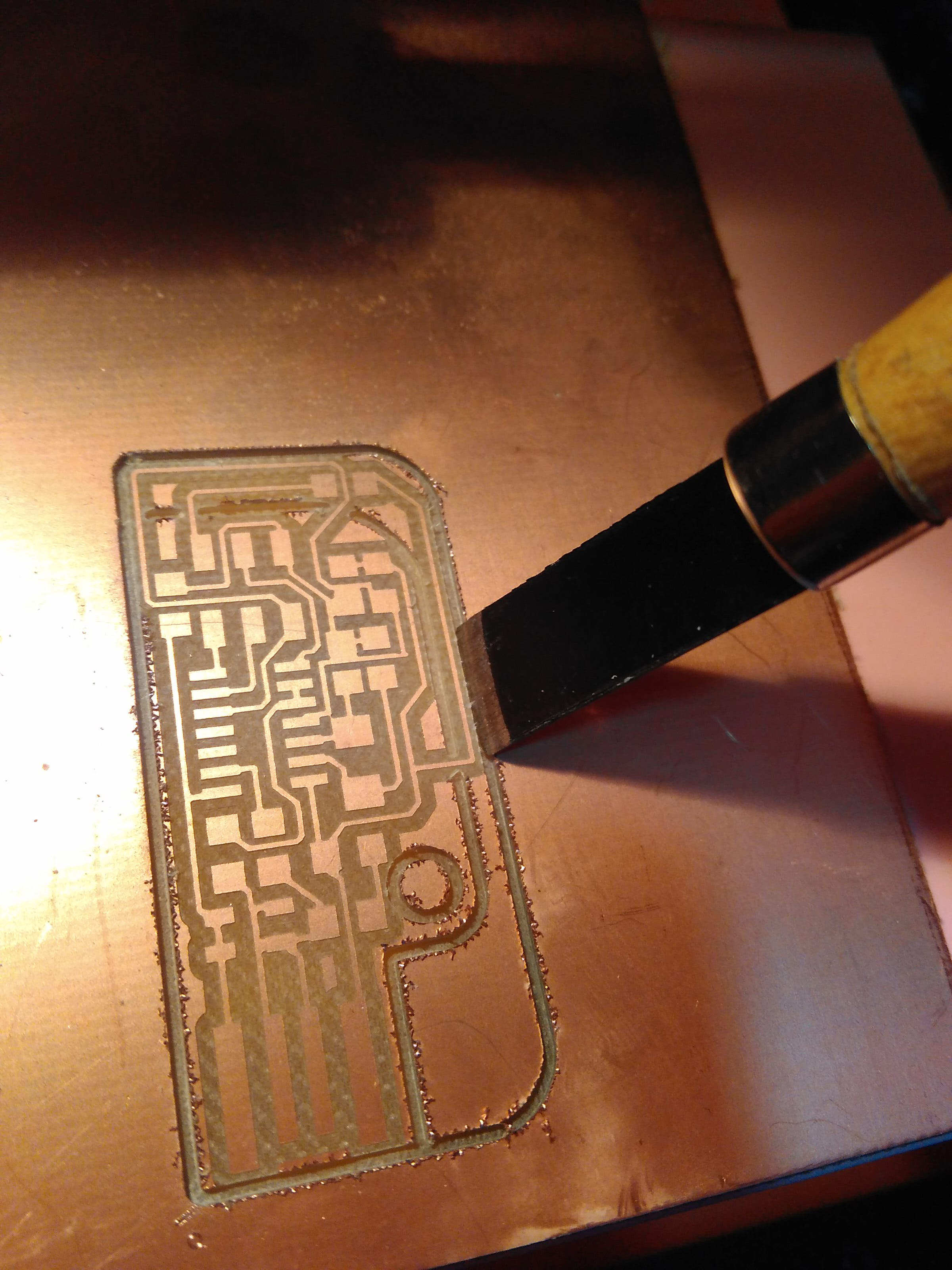
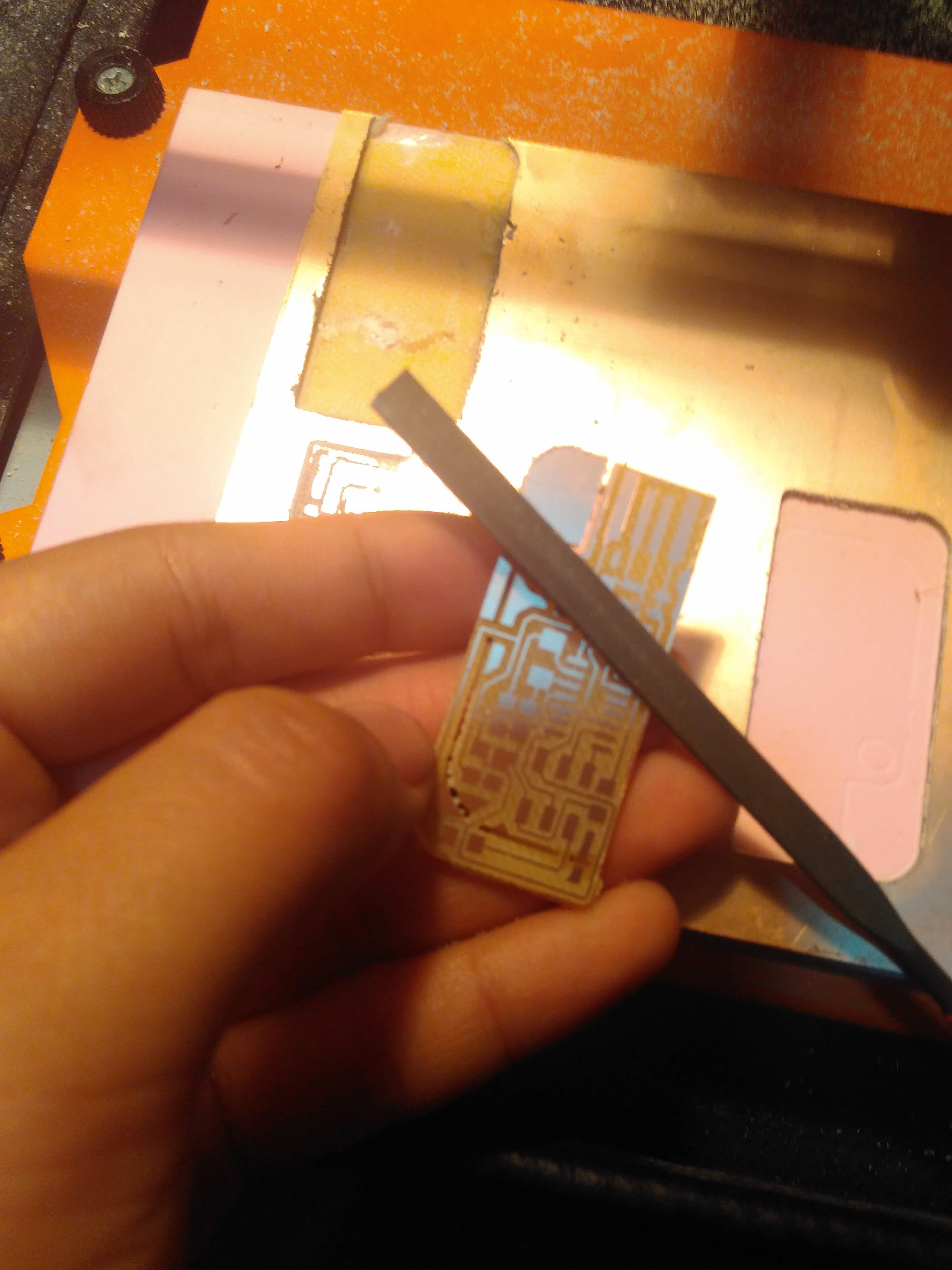
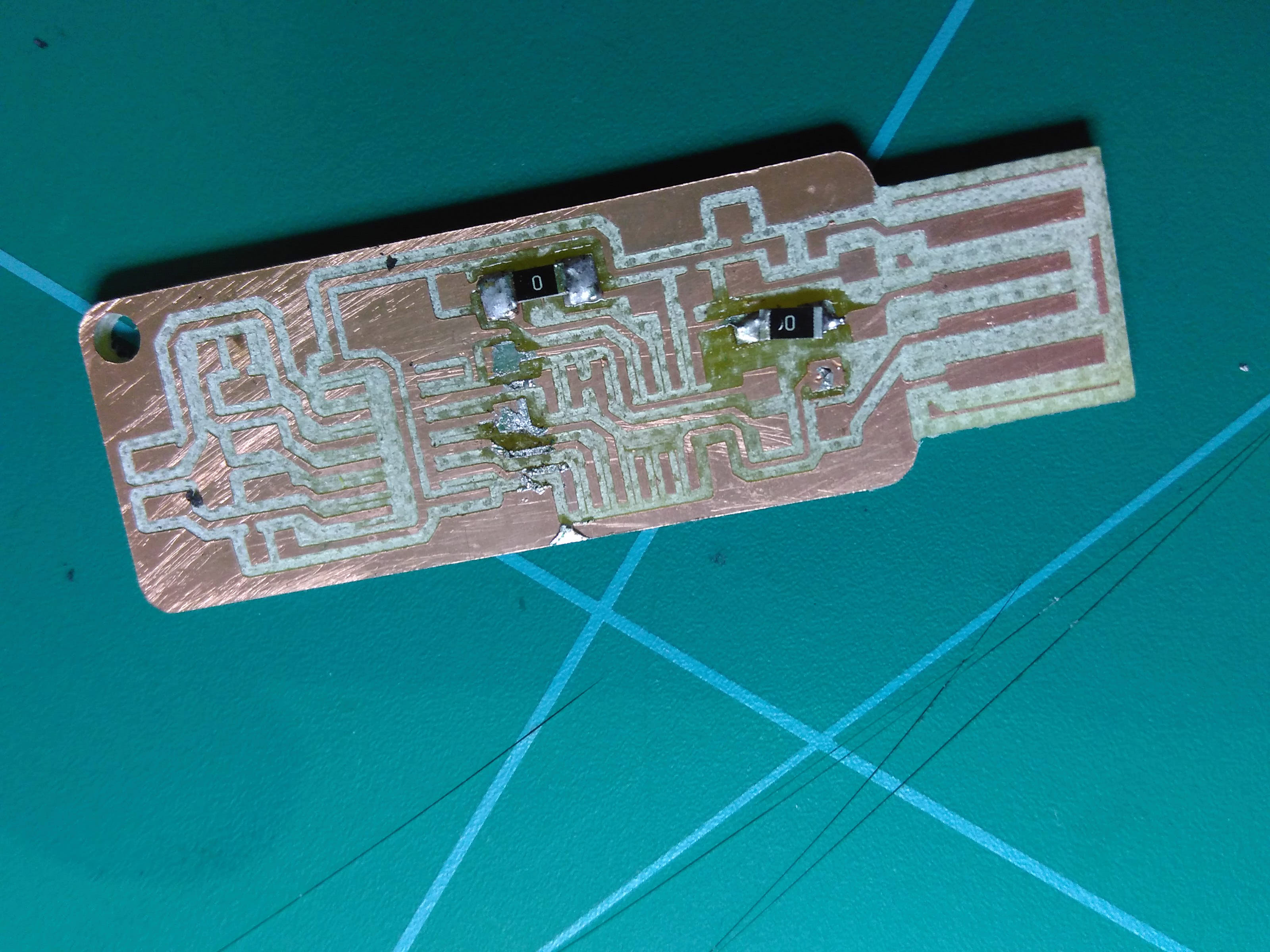
When the cutting process is done, vacuum the powder on the surface. Use a knife to loosen its edges and carefully sccop it out.
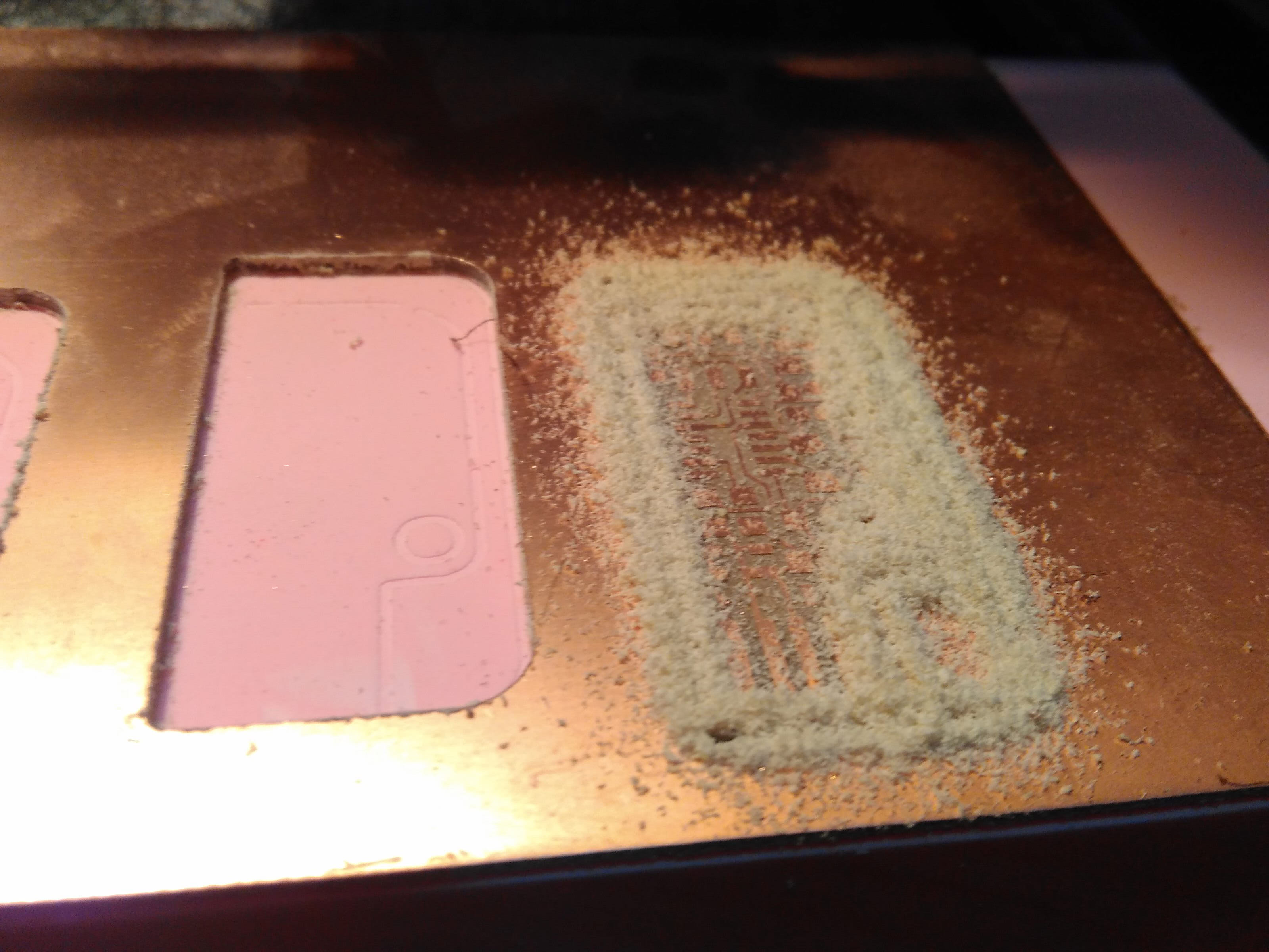
Finally scrub the surface and wash it with soap.
☞ Tips
Use doubles-sided tape to stick the back surface of the copper board and the cutting board. Make sure the copper board is absolutely flat everywhere to avoid damage to the endmill.
Soldering Practice
23 Feb
Week4 Electronics Production; soldering
I mainly practiced removing wrongly-soldered component or extra tin wire. I tried two different tools which were new to me: air gun and copper braid.
To remove a component with an air gun, I heated the air gun with the temperature at about 240 degrees. Then I blew it over the component with one hand and clip the compnent with another hand. After a few seconds the board would fall therefore separating the wrongly-positioned component from the board.
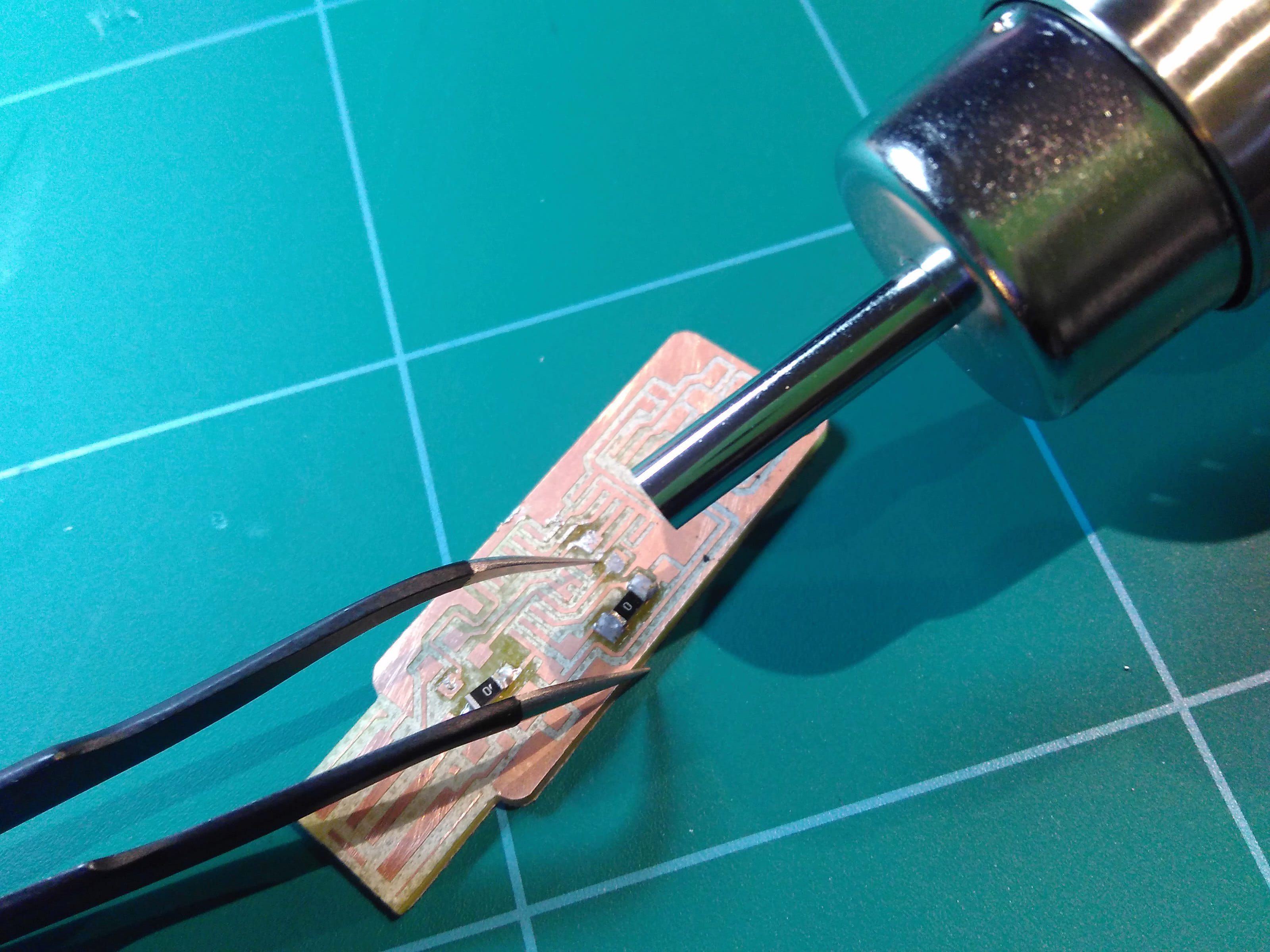
before
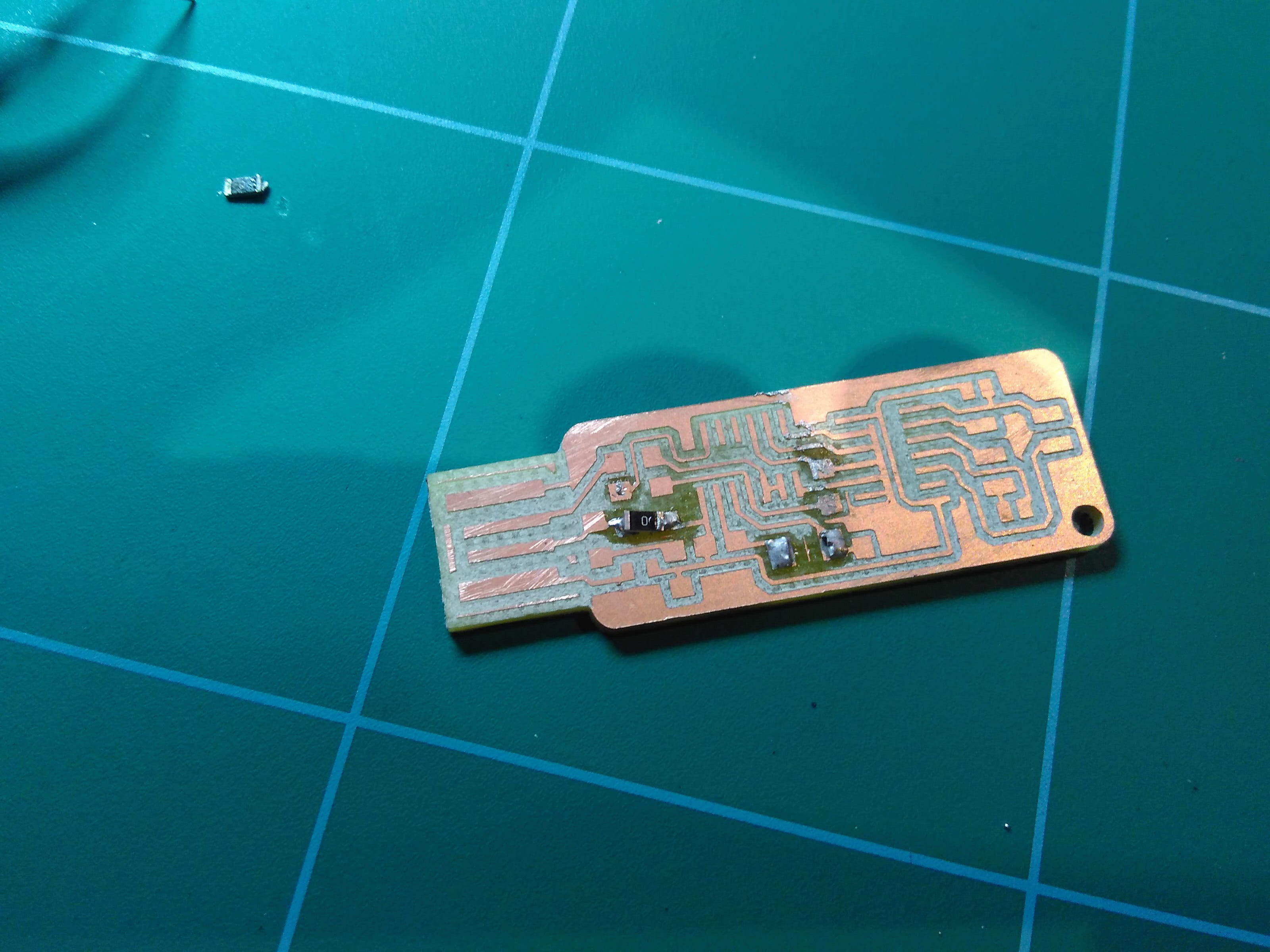
after
To remove the extra tin wire, I can either use a solder iron with flat head or a copper braid. In Fablab Shanghai we only have braid so I practiced on that. Place the braid on top of the tin you intending to remove and press the braid where covers the tin with the solder iron. Until the silver-colored tin dissolves onto the golden-colored braid, the process is done.
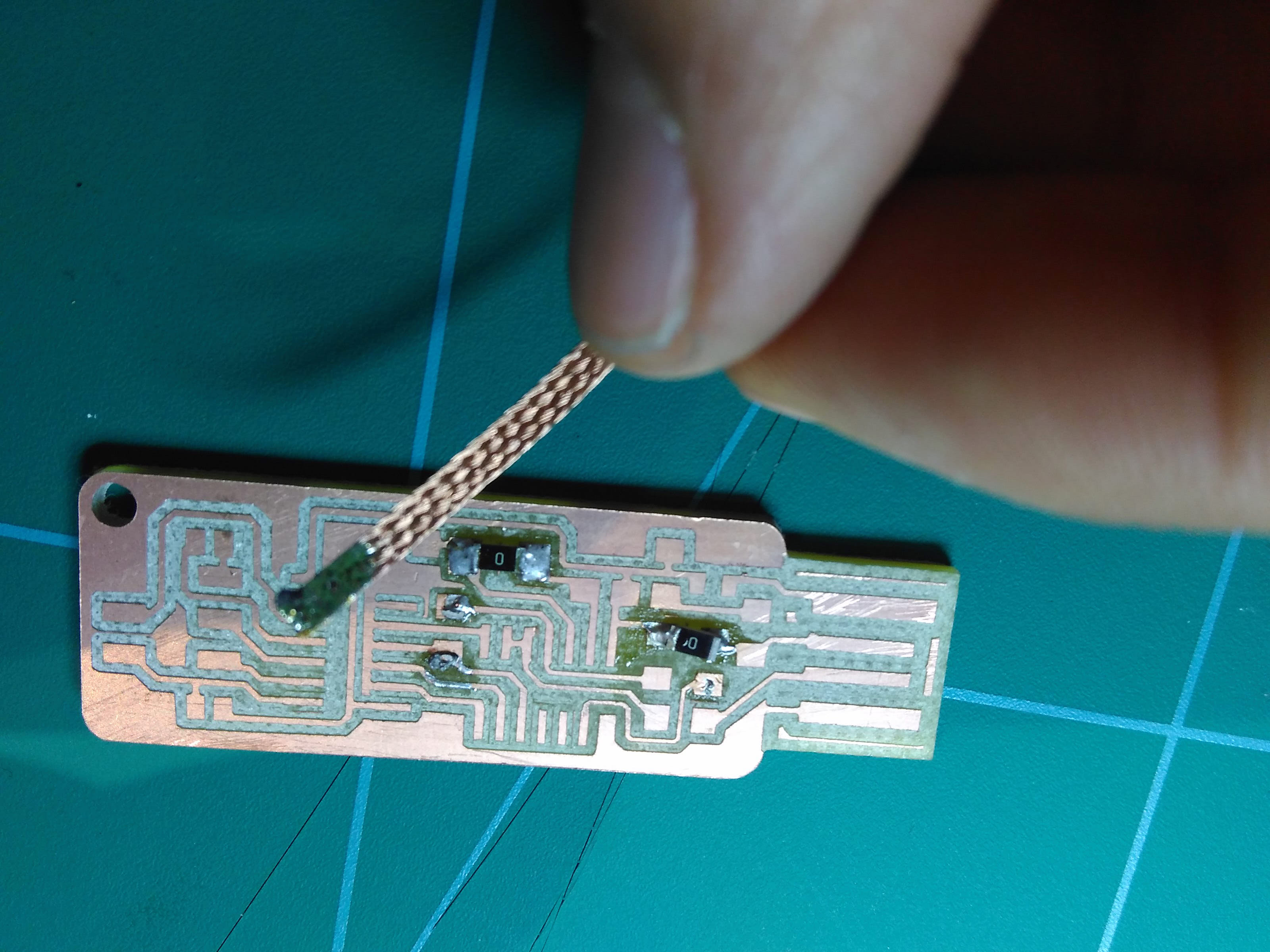
before
after
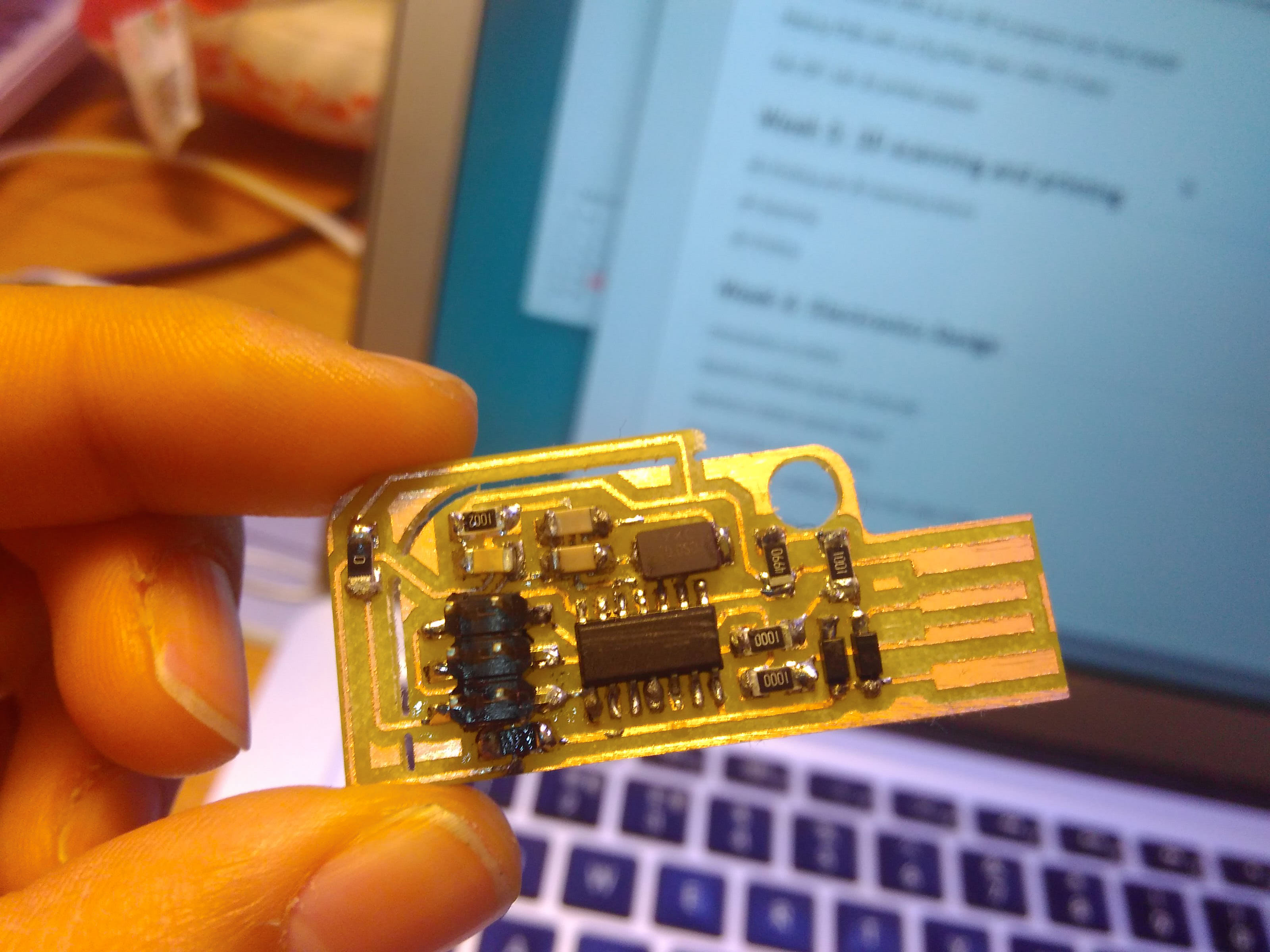
This is my final work following Valentin's design of the ISP board.
☞ Tips
1.The solder iron performs the best at around 450 degrees.
2.It's easier to make one leg of the component fixed.
3.Do check the board by comparing it with the png design to see if there's anywhere uncut to avoid short circuit.
4.Solder the components from the inside to the outside.
5.Capacitors can be piled up when soldering. Say if there's no 20pF capacitor, I can use a double-decked one consisting two 10pF capacitors instead.
6.If there's any wire unconnected, we can always make up for that by connecting the broken place with solder tin.