LASER CUTTER
Design and drawing
For this assignment week we had to design, make, and document a parametric press-fit construction kit.
Parametric design is the generation of geometry from the definition of a family of initial parameters and scheduling of formal relations there are between them.
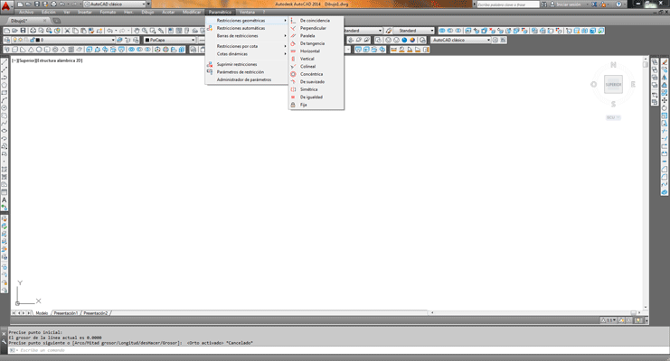
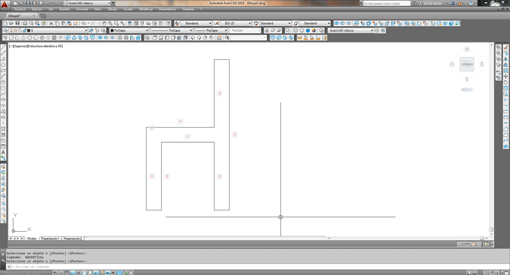
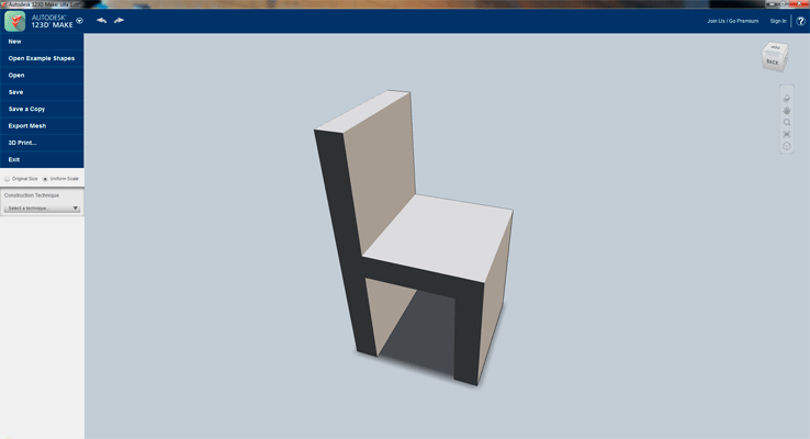
I decided to design a small cardboard chair, to draw it I started with Autocad, this software has some parametric tools as for example, two lines have to be parallel or perpendicular or tangent.
Once I had the volume in millimeters of the chair I exported the file in stl to do a ribbing with 123Make software.
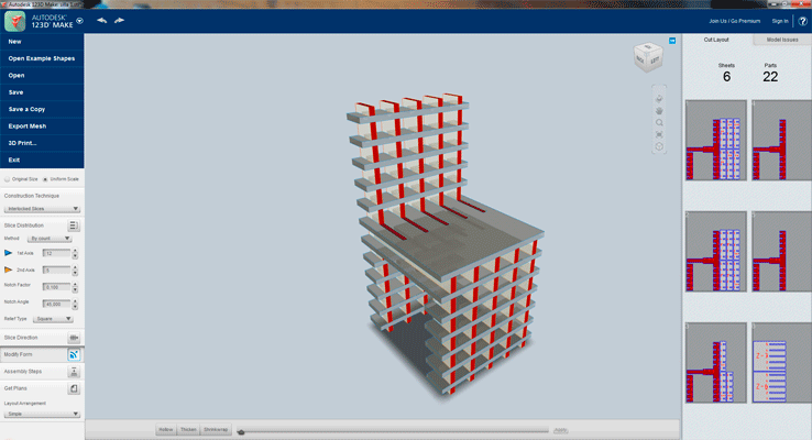
123Make: I imported the stl file.
123Make is a parametric software that lets you turn 3D models into 2D build plans.
I decided to do perpendicular ribbing:
- 11 Horizontal divisions
- 5 Vertical divisions
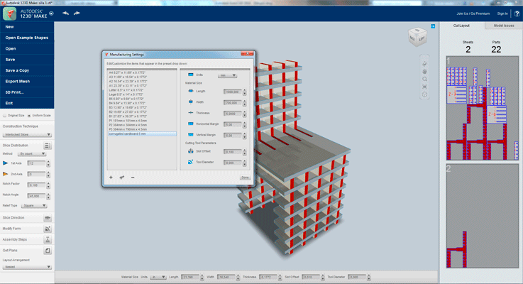
Once you have the model as you want, you can modify the parameters of the cutting material, things like the dimensions and the thickness of the material.
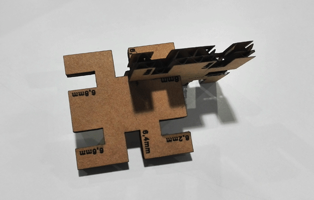
I had 1000x700x6mm of corrugated cardboard, you can also write the tolerance of the press-fit pieces. I did a test of press-fit cardboard and I found that you lose 0.2 mm cutting the piece with the laser cutter so I wrote it in the 123Make parameters.
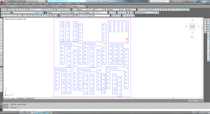
Once I had everything I exported the file in dxf.
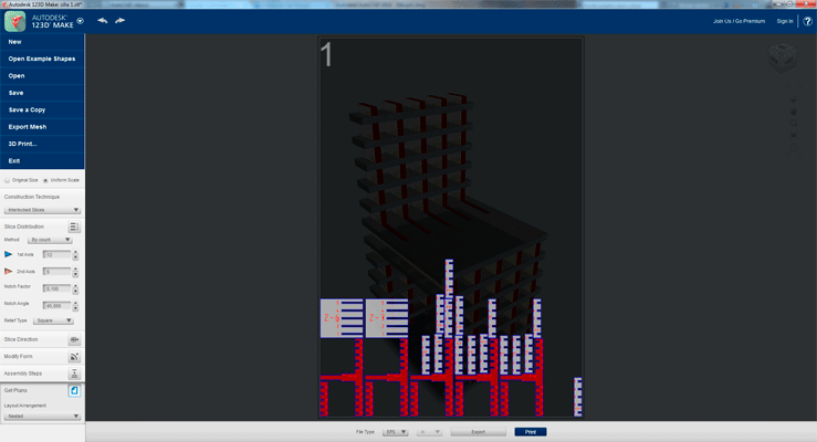
Placing pieces that makes 123Make is not very effective so I reposition the parts in Autocad to save material.
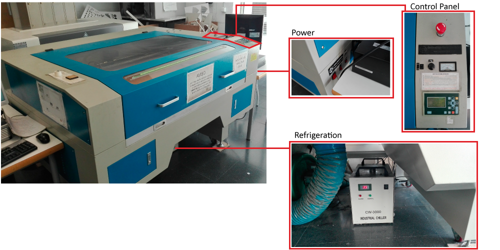
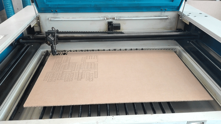
The machine and the program
The machine that we have in our fablab is a Golden Sing Laser machine it has watercooling.
At the top of the machine we can see the control panel and on one side the power buttons of the machine.
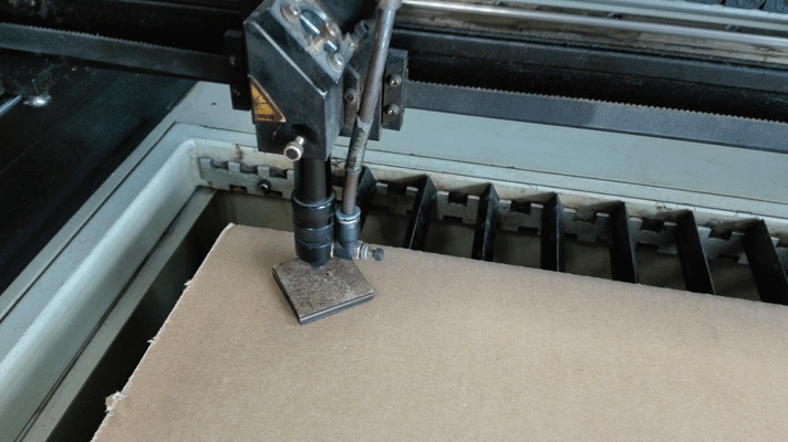
The first thing we have to do is to manually position the head at 1 cm of the material that we will cut.
Press-fit test:
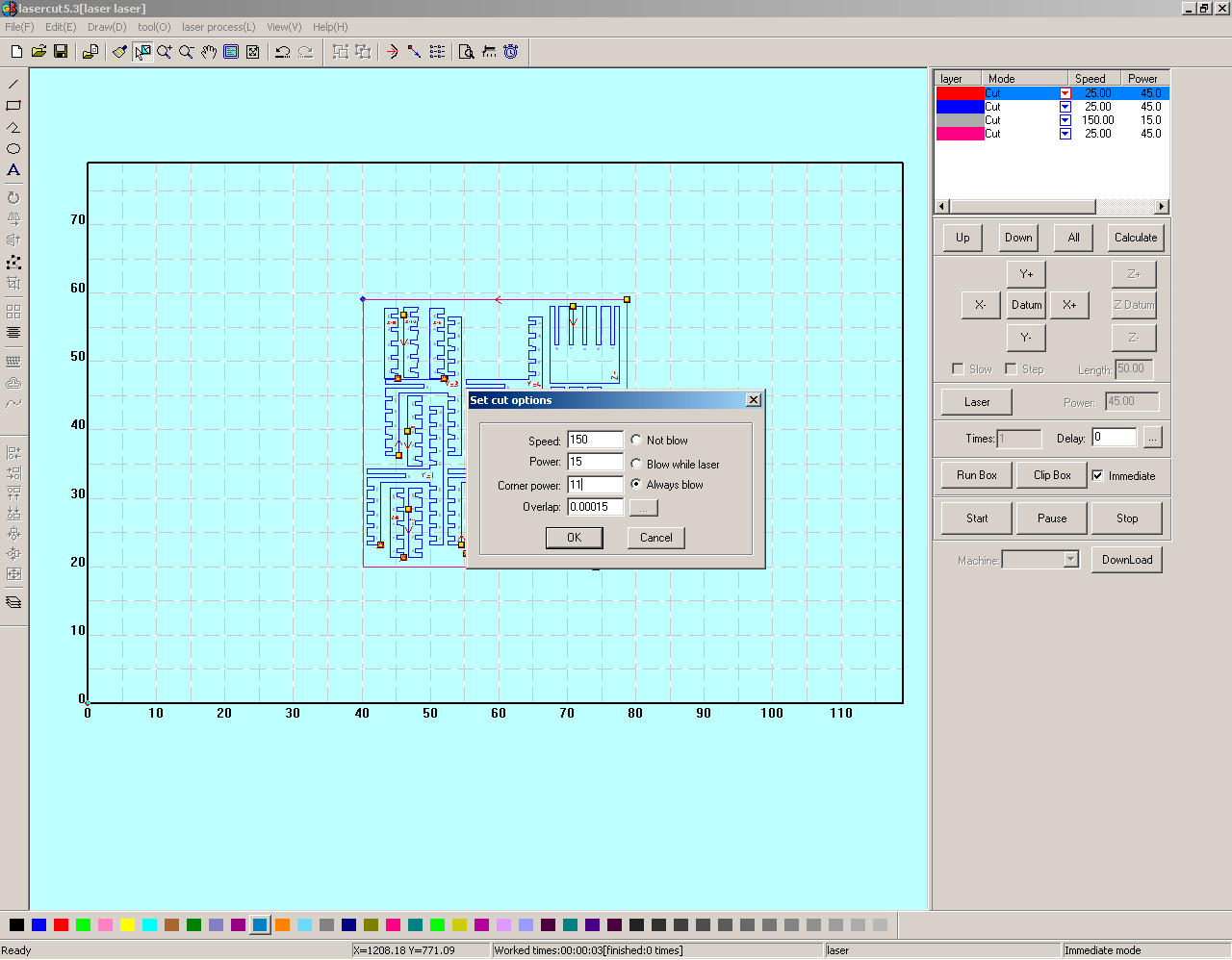
The program that our laser cutter uses is lasercut 5.3. The program identifies the colors as layers, so you can give different parameters to the different colors.
The parameters that I used for 6mm corrugated cardboard:
- Engrave: 150, 15, 11(Speed, Power, Corner Power)
- Cut: 60, 45, 40 (Speed, Power, Corner Power)
I did 4 layers:
- Two engraving layers
- And two cutting layers, the order of the cutting layers it is important because you should start from inside to outside because it is possible that while you are cutting some small pieces fall to the bottom, so if you have to engrave something inside of it if the piece moved you cannot engrave it later.
Once you have everything you have to download the file to the machine.
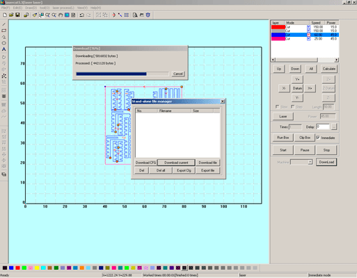
And using the machine control panel you put the head where you want to start, and after doing a size test you press start, if you want to stop or pause the machine you also can use this panel to do it.
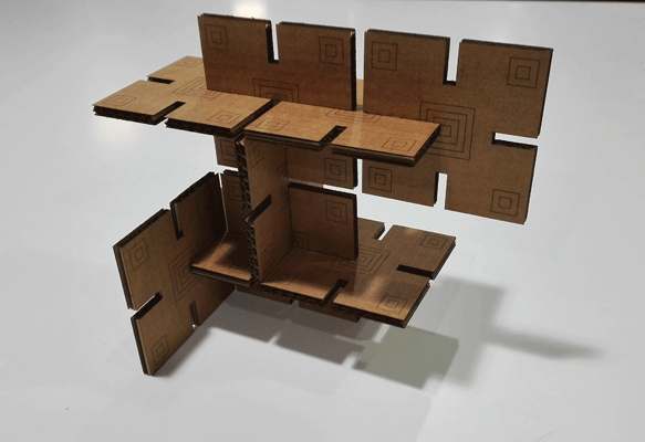
The pieces
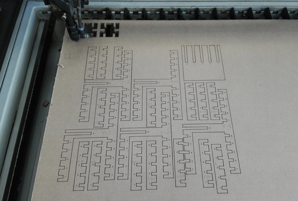
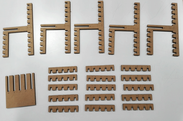
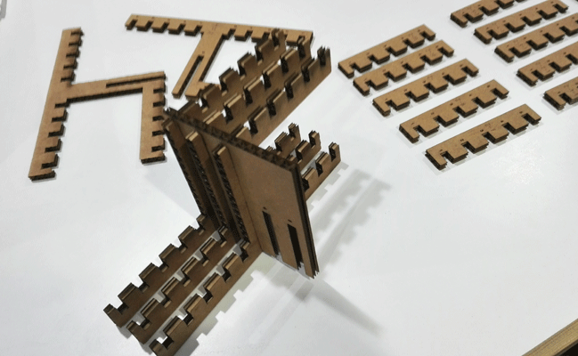
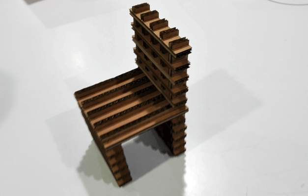
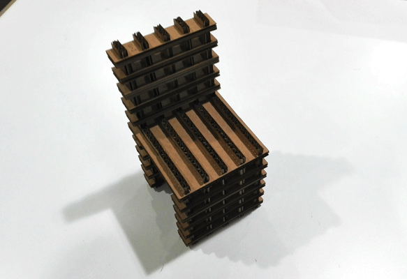
The final result
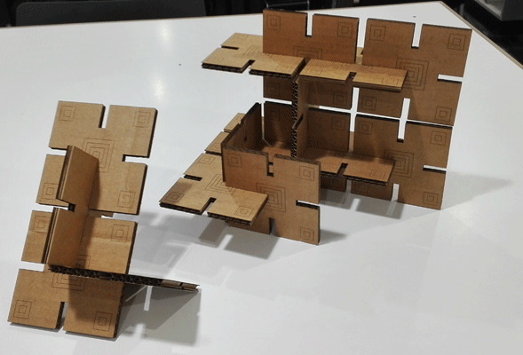
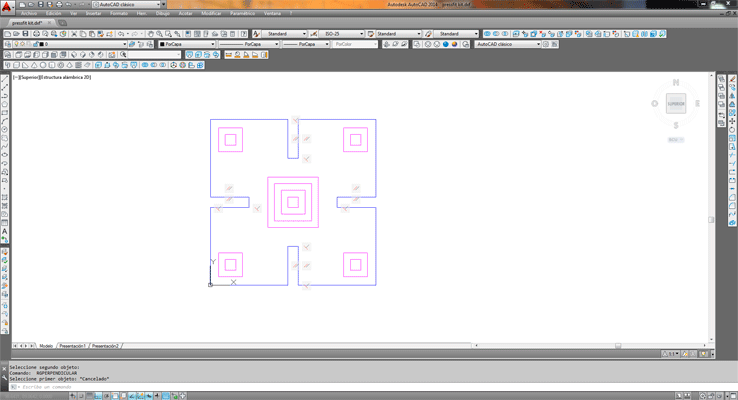
Press-fit kit
I also did a press-fit kit to construct different volumes with the same module.
To draw it I used Autocad giving it some parameters and knowing the tolerance that I saw in the previous test that I show before.
I did it in 6mm corrugated cardboard and the cutting values that I used were:
- Engrave: 150, 15, 11(Speed, Power, Corner Power)
- Cut: 60, 45, 40 (Speed, Power, Corner Power)
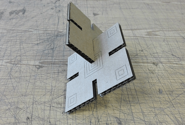

The final result