Riyas P.K-Fab Academy 2016
Final Project
Iteration 2[Update 27-07-2016]
I have redone my project with massive improvements.The documentation of the first version of my project can be found on the bottom of this page.
Process involved
Computer-aided design
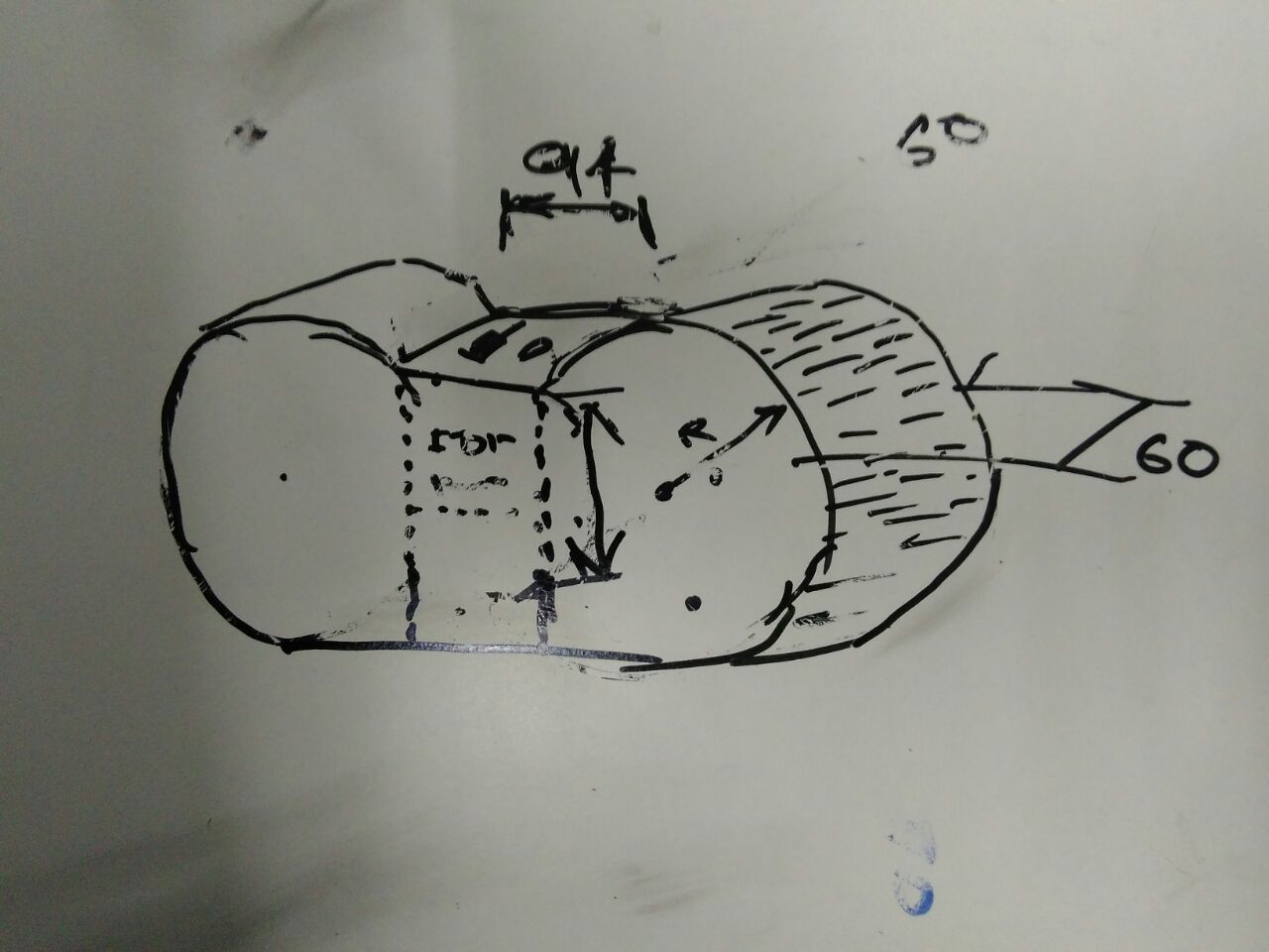
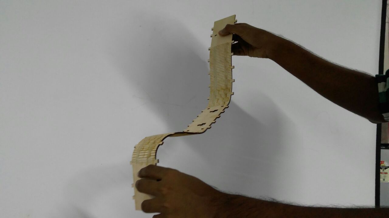
For a better physical feature and looks I decided to make the body as pressfit.First I draw a basic sketch of it.I decided to use kerf for curvature of the body.The front and the back of the body is transparent acrylic sheet.
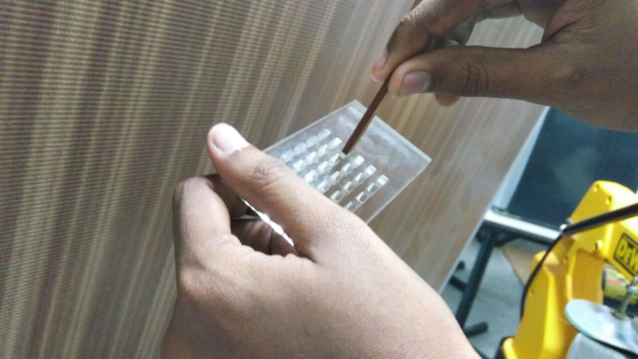
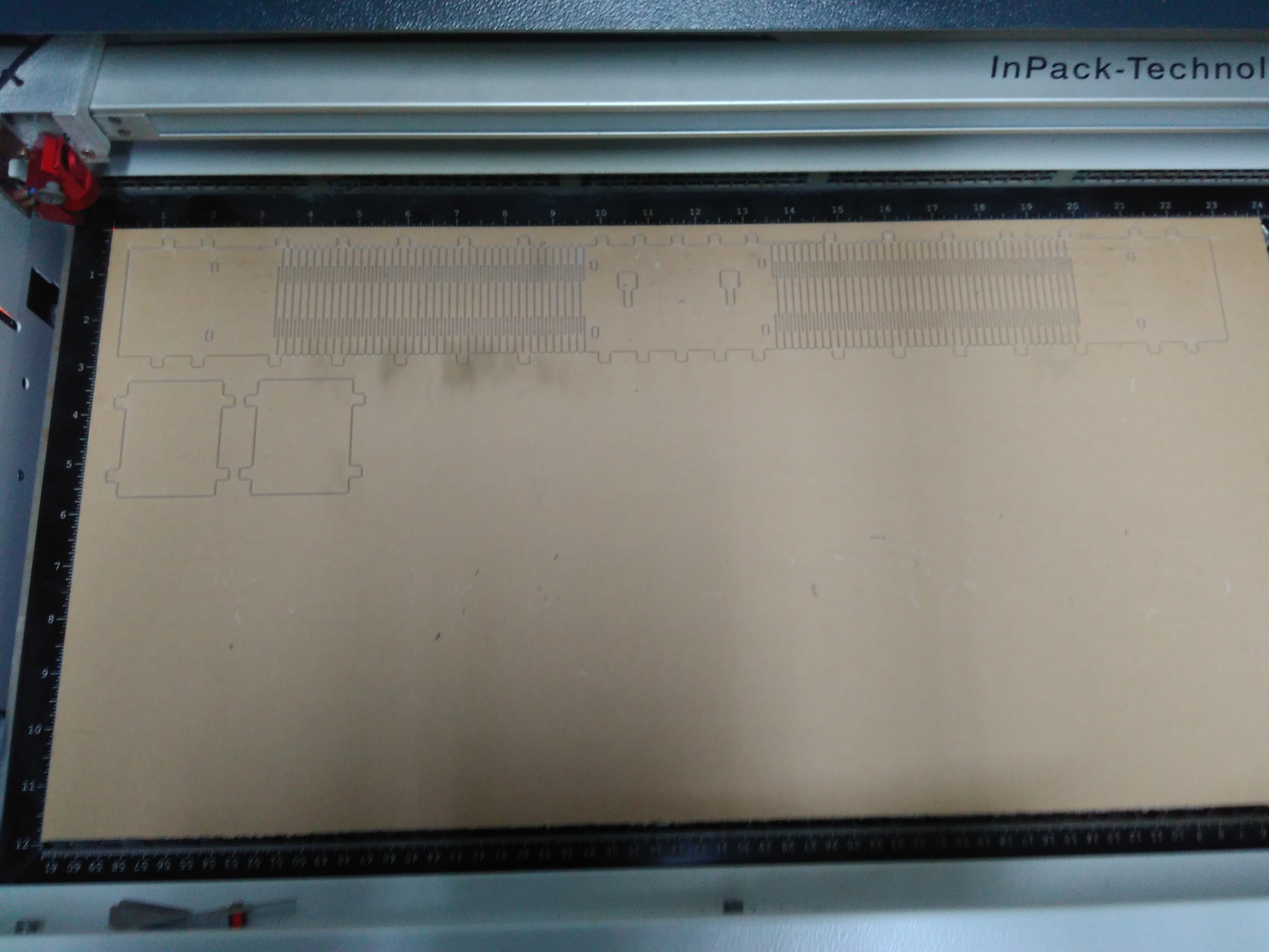
Before gettin into design I had to check the fit between acrylic sheet and plywood,for this I made a test cut in a 6mm acrylic. the acrylic contained slots of multiple sizes. Then i cut a piece of 3mm plywood having 6mm width. Then i tested the fitness and tolerence between acrylic and plywood by trying to fit the wood piece inn the acrylic slots one by one till found a slot that the wood piece perfectly. I will be using this slot width in the designing of the box.
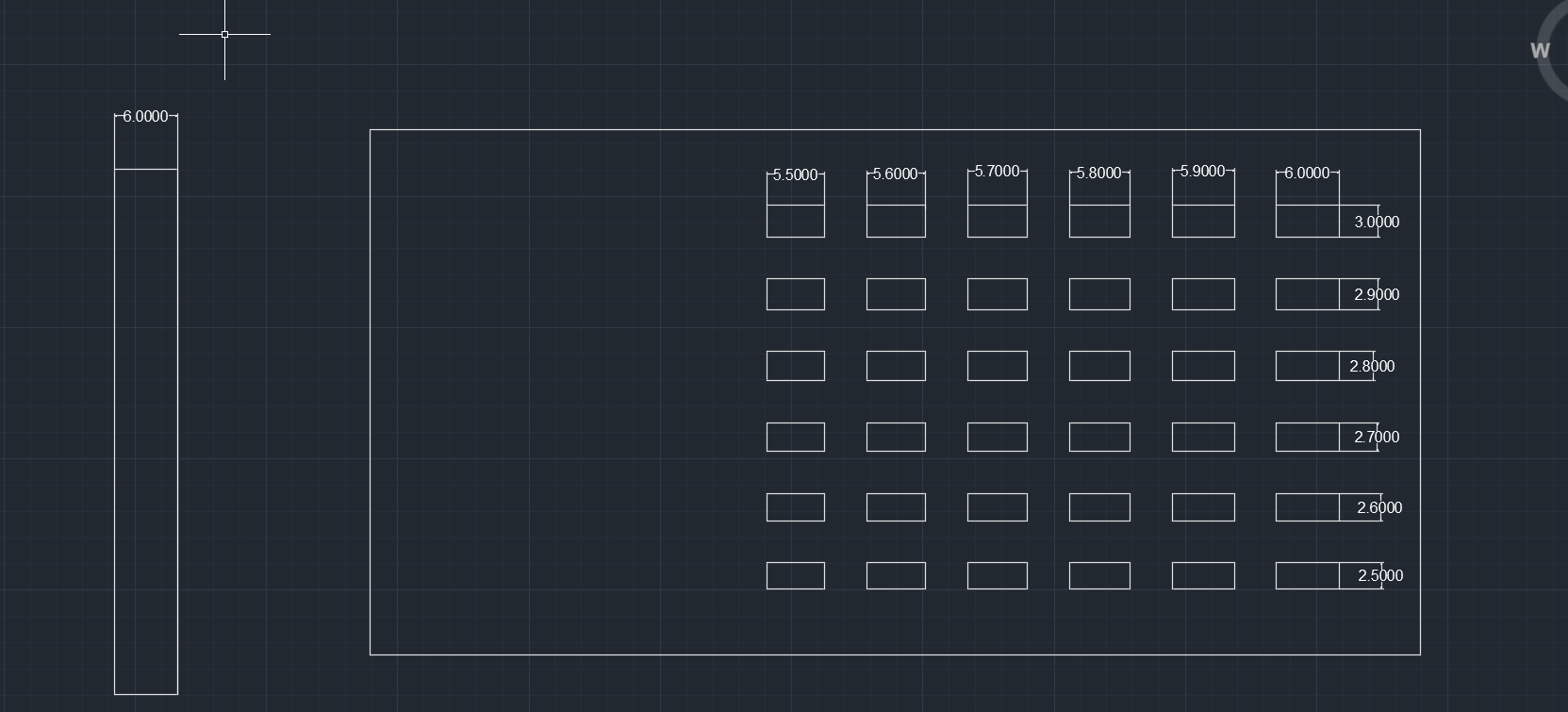
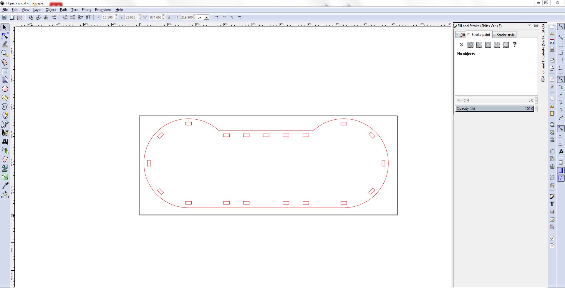
For designing I decide to use Autocad since it is comparitively easy to use for 2D designs.After checking the thickness and fit I started to draw the front/back side of the body.
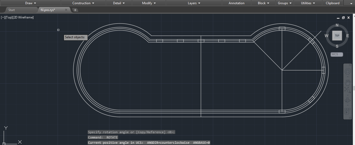
Then I draw the kerf using parametric equation,such that changing the radius of the kerf (r) we will get the exact length of the kerf.
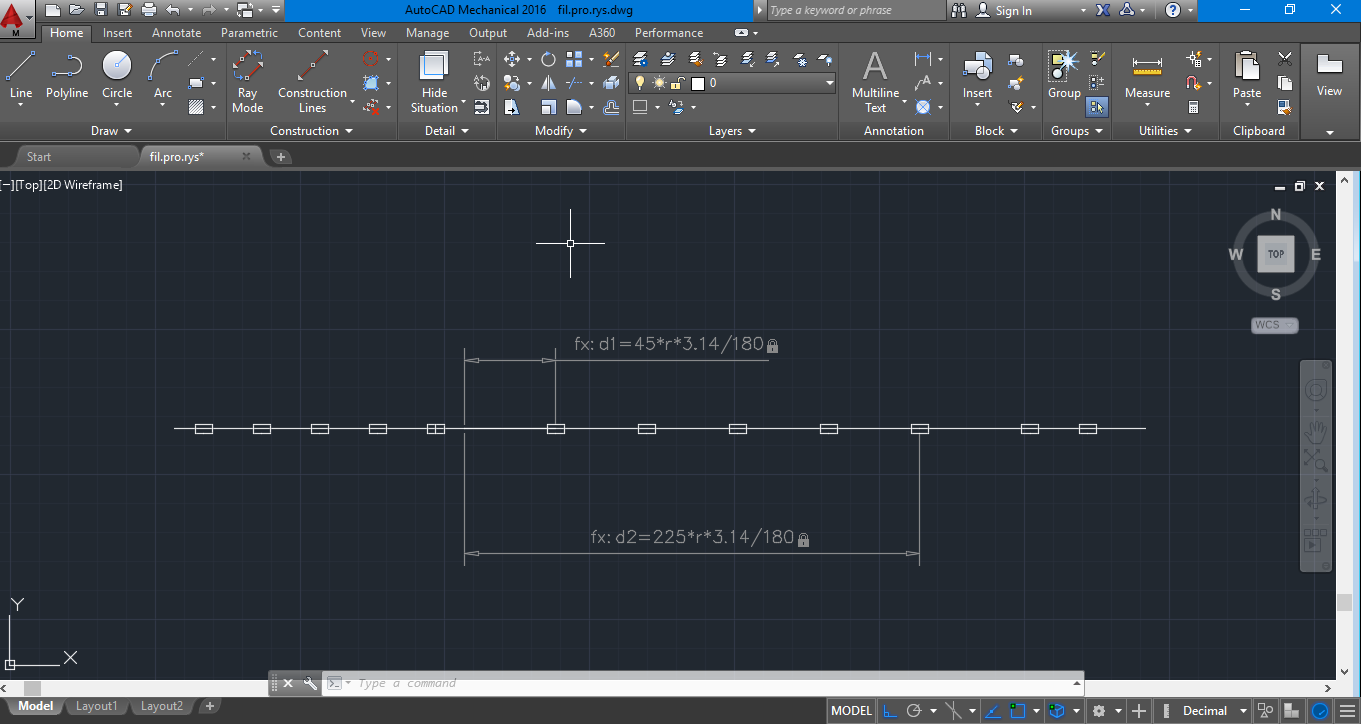
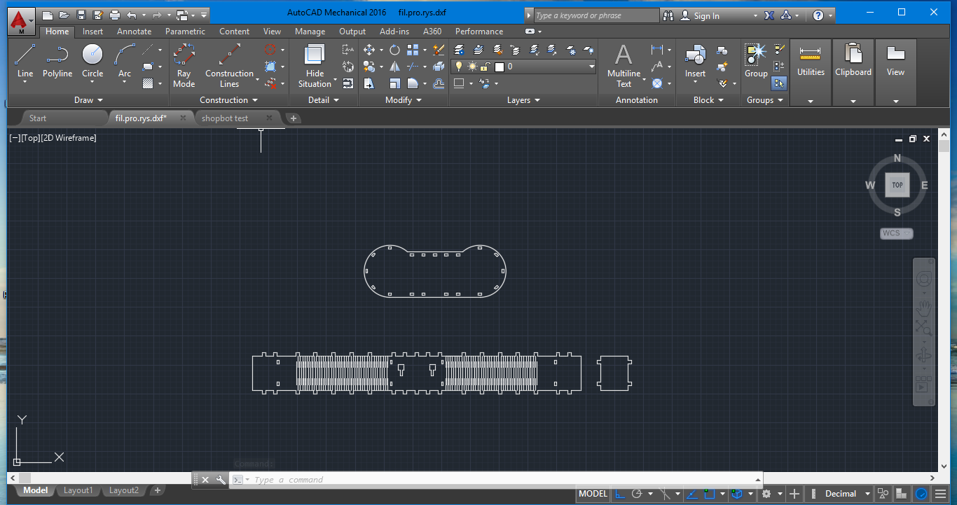
After completing the kerf I designed a seperator and saved it as DXF file format.
Files
Computer-controlled cutting
First I loaded the dxf file inkscape and placed only the kerf and seperater and change the color of lines to red.
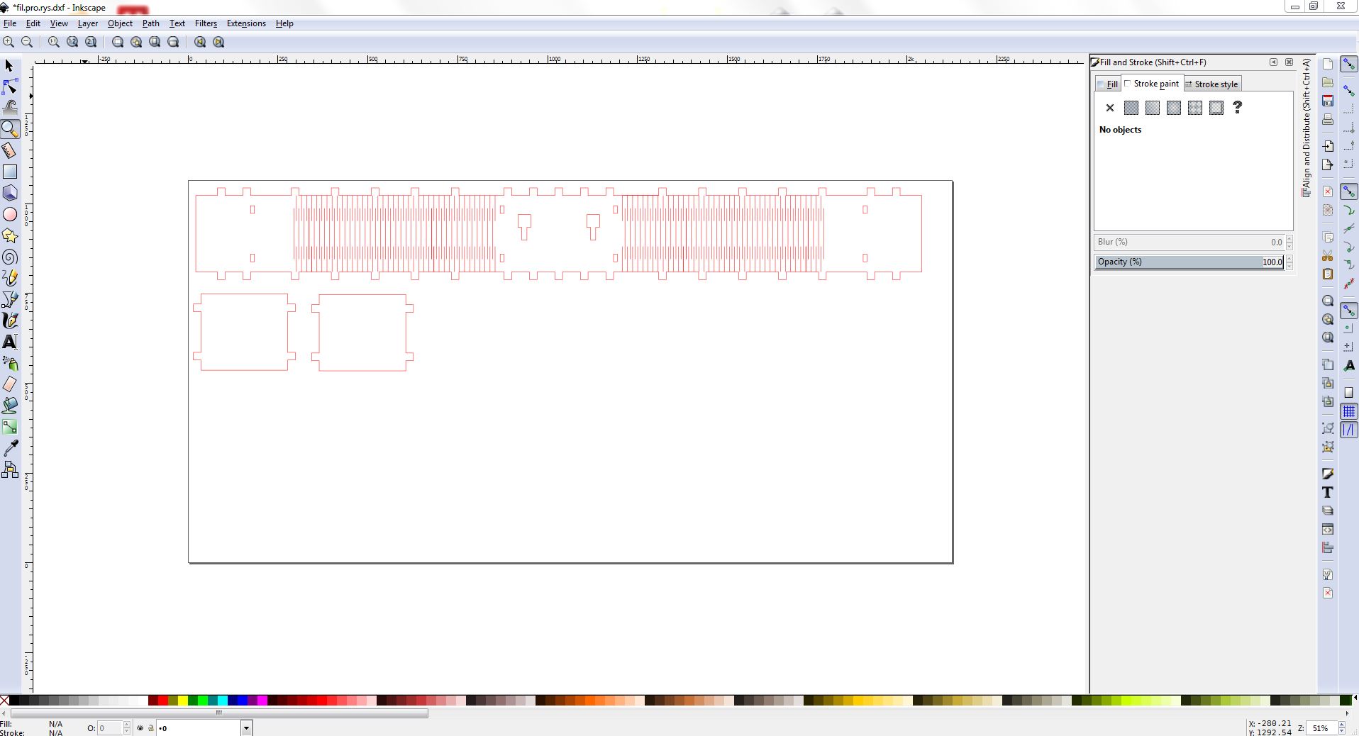
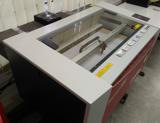
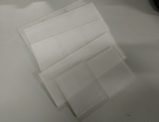
And then using Job control software and trotec laser cutter I cut the kerf and seperator in plywood.
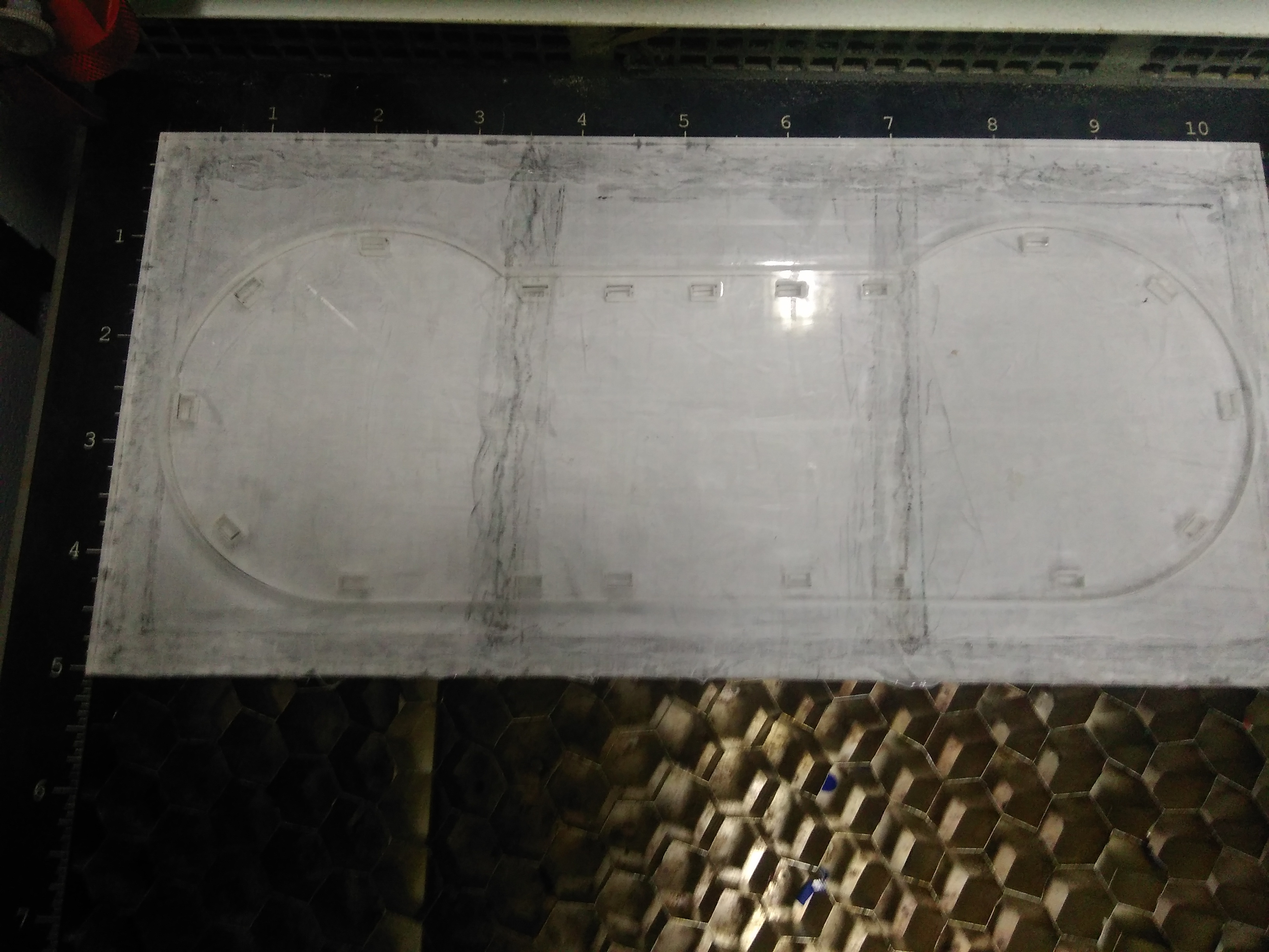
Then I added the front/back of the body in inkscape and changed the color to red, and repeat the process.But these parts are cut in previously used engraved transparent acrylic sheet(used for make the body in previous attempt).
Electronic Design
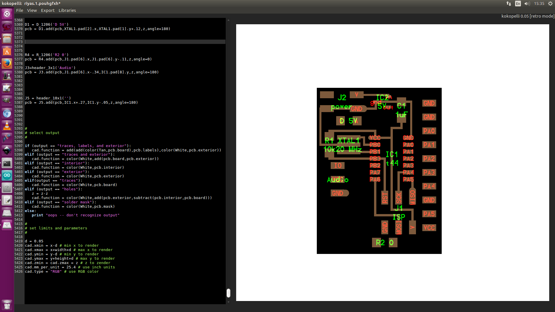
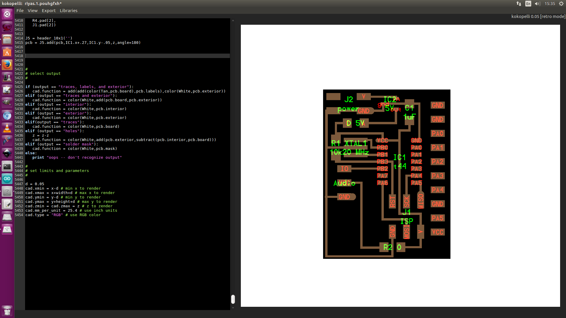
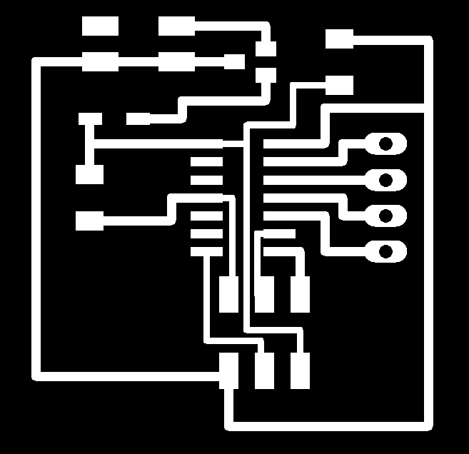
I designed two circuits for my project, one is main board and other is led strip board.The main board is designed using kokopelli.It is a basic board with attiny 44 as micro controller and many pins for connections.first of all included two libraries which is created by athif,libraries for 10x1 pins and 3x1 pins,then used 3 pin as audio pin,out of these 3 pins declared one asa ground,another one as vcc and third one as pin8 placed 10 pins on left side of the microcontroller,first 2 point of 10x1 pins connected as ground then reamining 2 to 8 pins connected to 0 to 5 of microcontroller.
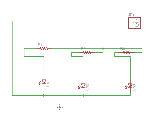
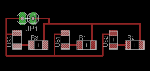
The led strip board is designed on eagle.
Files
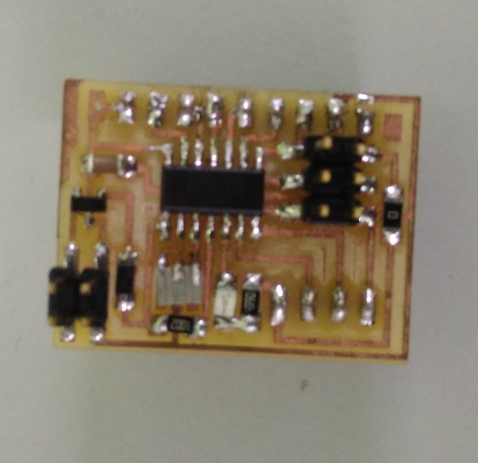
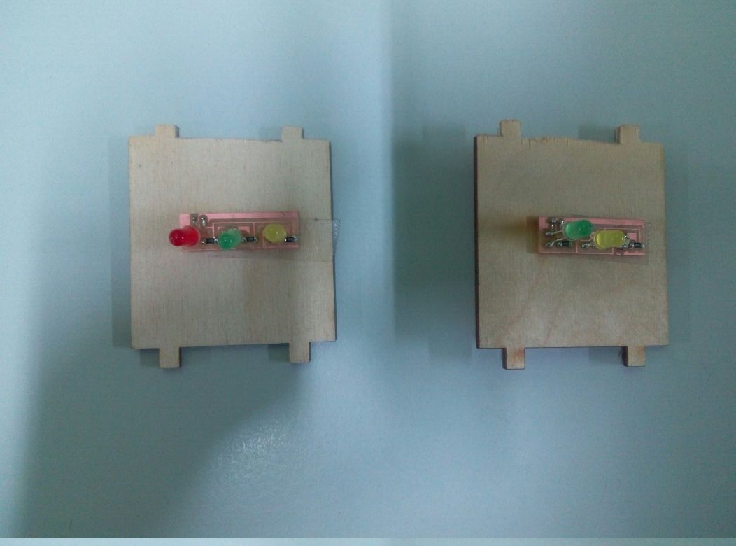
Electronic production
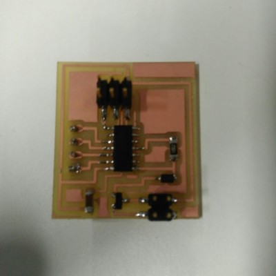
After designing I exported the png of interior,traces and holes seperatly.Using these files I milled the board and stuffed the board using required components.
Embedded programming
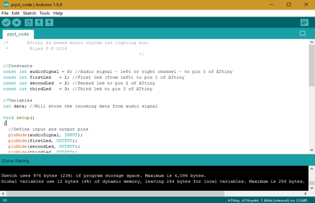
First I wrote a simple program in arduino after refering some existing programs.
The idea is to read the incoming data from audio signal and store it to 'data' variable.Then using this values, led's can be controlled.This functionality is similar to a VU meter. However, in my project, there is no waveform analyzing.
In this product I am designing, the sound from any audio device like a mobile phone which comes out through a standard 3.5mm audio jack, shall be connected to the board I made.
The signal from the 3.5mm audio jack is taken as an analog input.The analog audio input is read as oscillating voltages.These values are stored to a integer variable. In the program, this voltage value from audio jack is taken as input and 3 LED's are set as output. In the connection, each led is actually 3 seperate led's. The program compares the voltage value to against specific values and lights the LED's accordingly. If there is no audio signal, the LED's will become LOW.
To get this desired output, I have added three conditions, if the data value from the sound is between 5 and 20 the first set of leds lights up,else if the values are between 20 and 40 and the values are between 40 and 800 lights up the second set and third set of leds accordingly.
          /*  ATtiny 44 based music rhythm led lighting box.
            *  Riyas P.K 2016                                */

            //Constants
            const int audioSignal = 5; //Audio signal - left or right channel - to pin 0 of ATtiny
            const int firstLed   = 0; //First led (from left) to pin 1 of ATtiny
            const int secondLed  = 1; //Second led to pin 2 of ATtiny
            const int thirdLed   = 2; //Third led to pin 3 of ATtiny

            //Variables
            int data; //Will store the incoming data from audio signal

            void setup()
            {
            //Define input and output pins
            pinMode(audioSignal, INPUT);
            pinMode(firstLed, OUTPUT);
            pinMode(secondLed, OUTPUT);
            pinMode(thirdLed, OUTPUT);
            }

            void loop()
            {
            //Read the incoming data from audio signal and store it to 'data' variable
            data = analogRead(5);

            //Make some cases to control the LEDs.


            if (data > 5 && data < 20 ) {
            digitalWrite(firstLed, HIGH);
            }

               else if (data >= 20 && data < 40) {
               digitalWrite(secondLed, HIGH);
            }
               else if (data >= 40 && data <= 800) {
               digitalWrite(thirdLed, HIGH);
            }
            else {
              digitalWrite(firstLed, LOW);
              digitalWrite(secondLed, LOW);
              digitalWrite(thirdLed, LOW);
                 }
              delay(20); // a small delay
            }
File
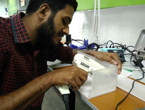
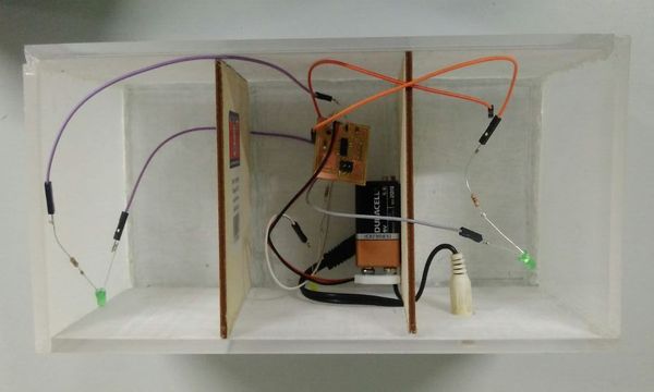
The board is programmed using FabISP and arduino ide.After successfull programming of board I decided to test whether the code works.So the connections are made according to pin configuration using connector wires and for audio input I used a 3.5mm stereo Jack to twin RCA sockets adapter Cable.The left channel of the cable is used as audio input which is connected to board and right channel is connected to speaker.
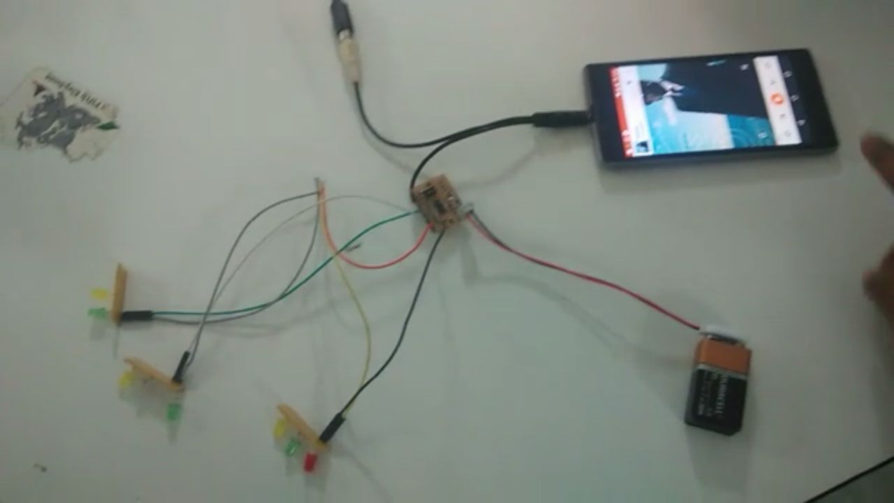
Here is a testing video:
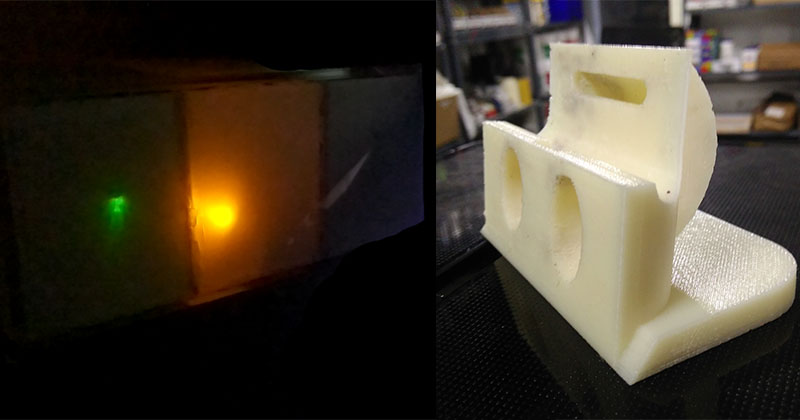
3D printing
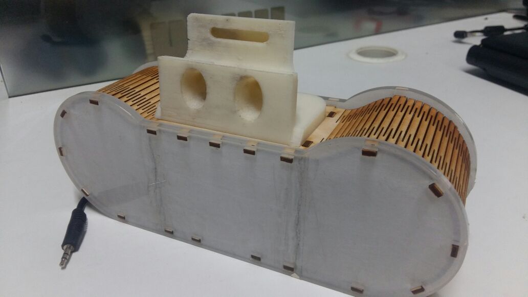
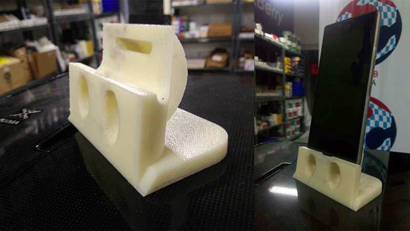
I did not change the 3D printed sound dock.The detailed descrption of design and printing can be found below.
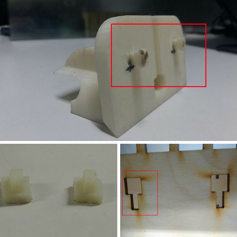
I also designed and 3D printed two small attachments for the sound dock,so I can place the sound dock over the body of rhythm box with a lap interlocking mechanism.I did this because I don't want to waste more material.So these two attachments are glued to the back of the sound dock.
Assembly
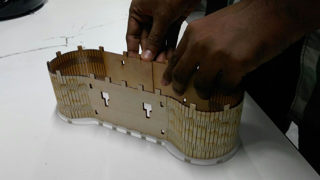
First fixed kerf press fit to front side part
sticked LED Strip on seperator
 /
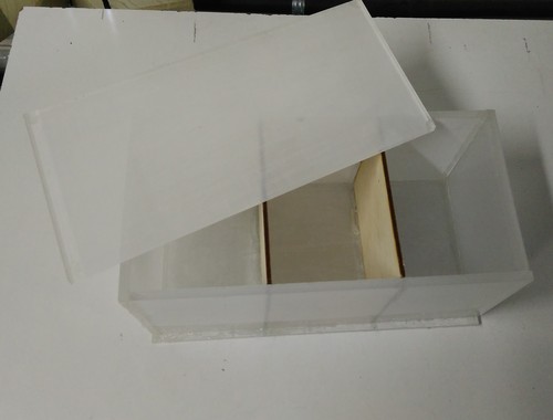
/assembled seperator inside the box,here is the top view
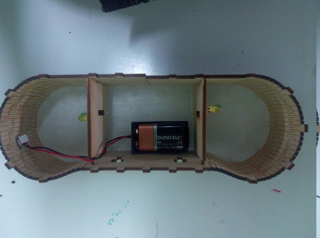
Positioned main board and LED strips inside the box,and fixed the wired connection. As of now, the battery holder is placed outside the case. In the next iteration, I am planning on moving the battery holder to inside of the case and also add a power on/off switch to the device.
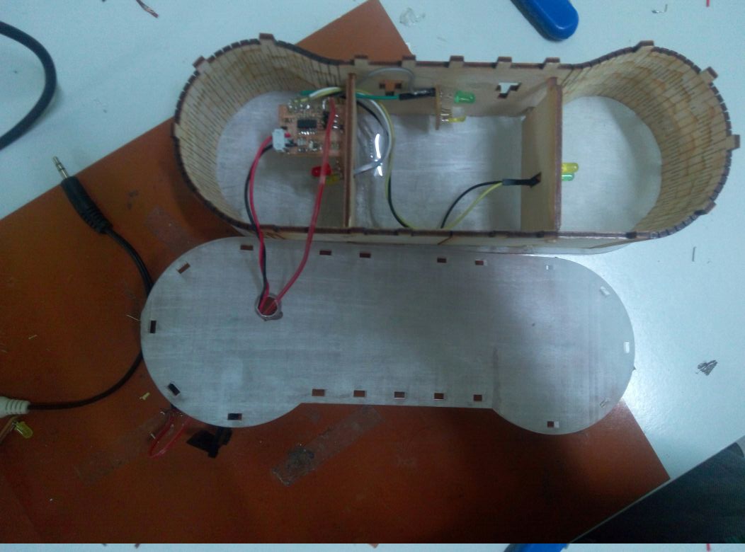
Back of the body is also filtted and completed the enclosure.
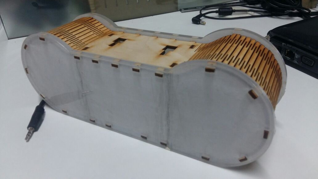
Then sound dock is locked on top of the enclosure.
Vinyl Cutting
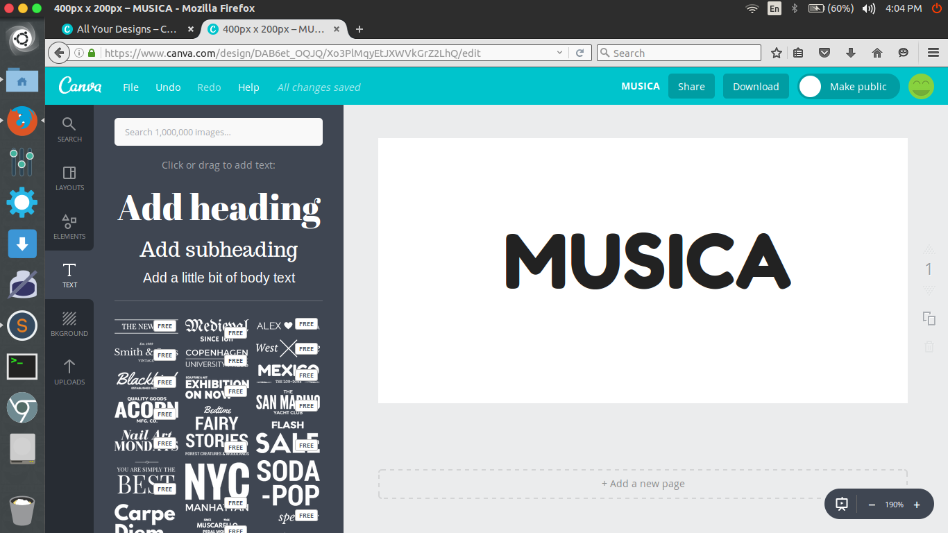
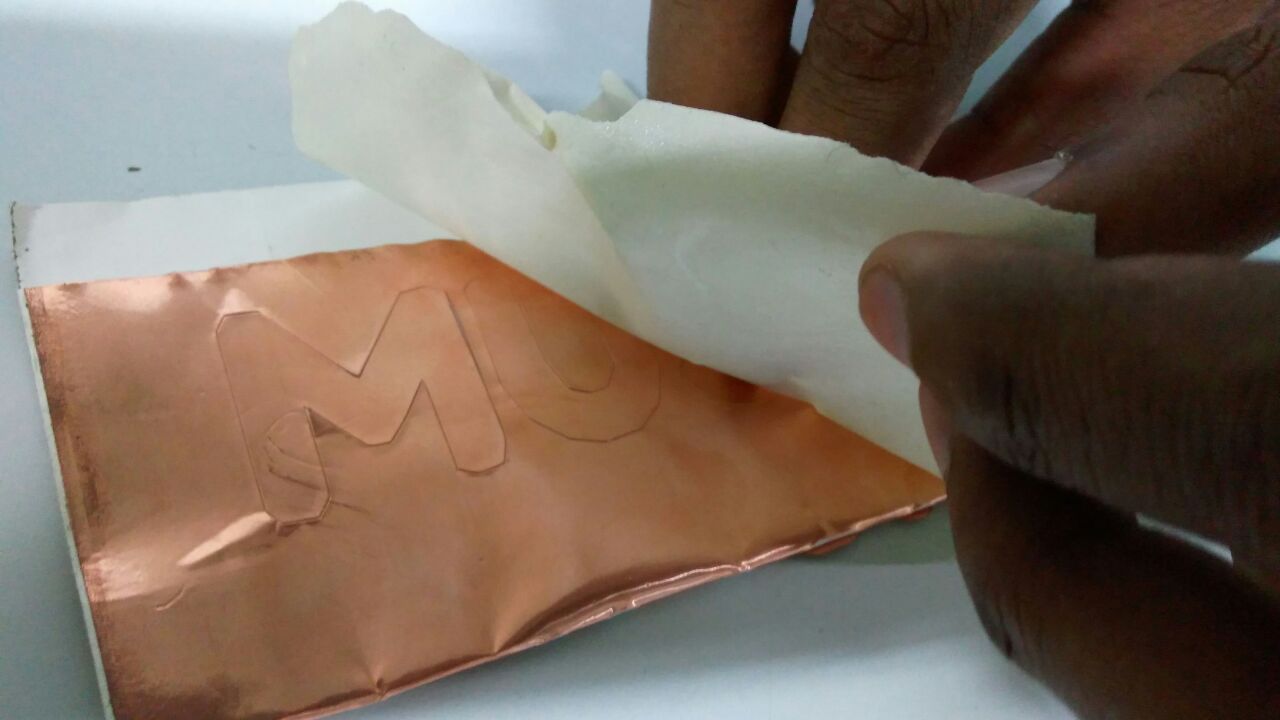
Now, I have reached the final leg of the project and here I am branding the product as "MUSICA".To give a unique appearance to the product I will be adding a copper sticker branding.The design was made in canva.com, an easy to use online tool for making awesome designs.In canva I drag and drop a heading musica and used a simple font.
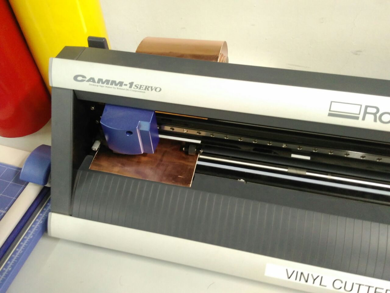
I loaded copper sticker roll to the roland vinyl cutter available at our fab lab.I used copper sticker instead vinyl sticker to make my product look good.
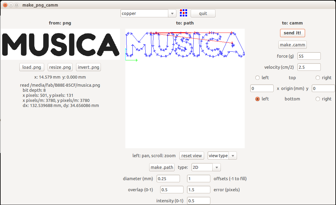
The downloaded image from canva is loaded in fab modules and selected material as copper.Then selected make.path--> make.camm --> send it.Thus the sticker is cut perfectly.
Then I stick the copper sticker to my product using masking tape.
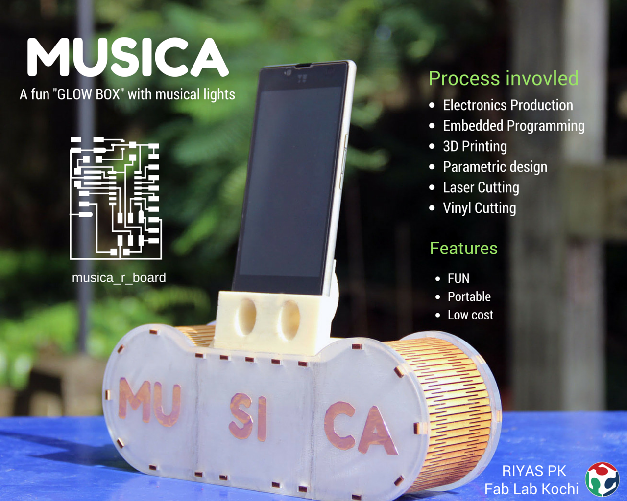
Here is a hero shot of the final product.
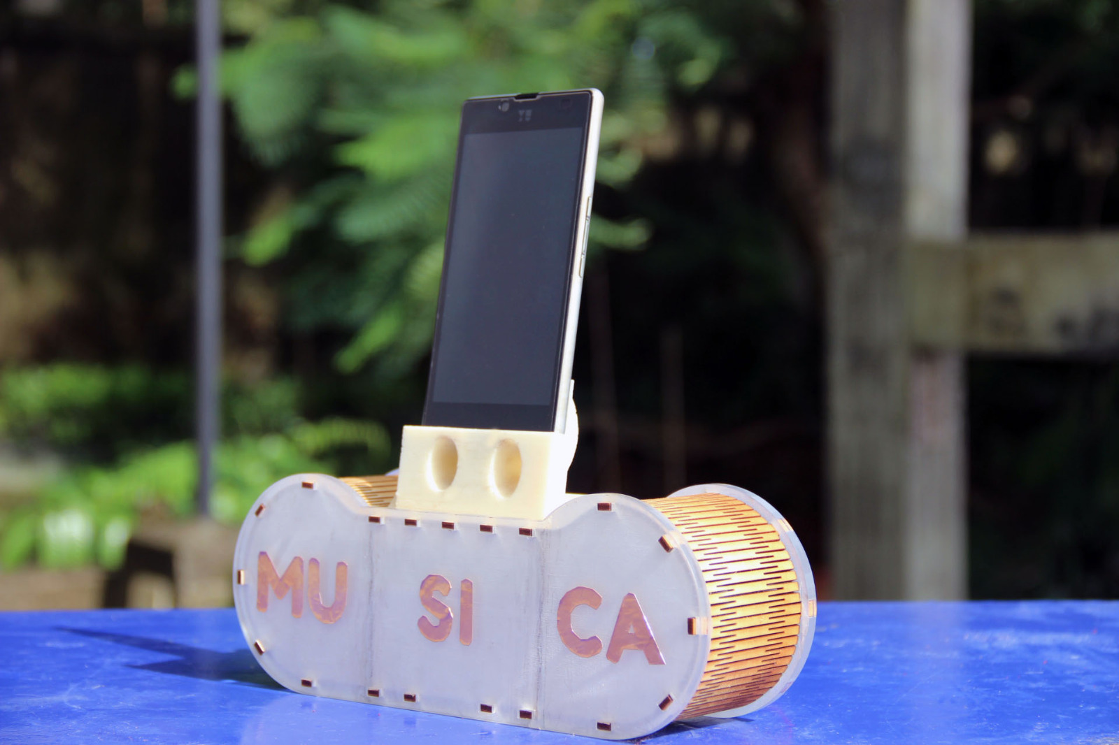
Here is the musica in action:
Iteration 1
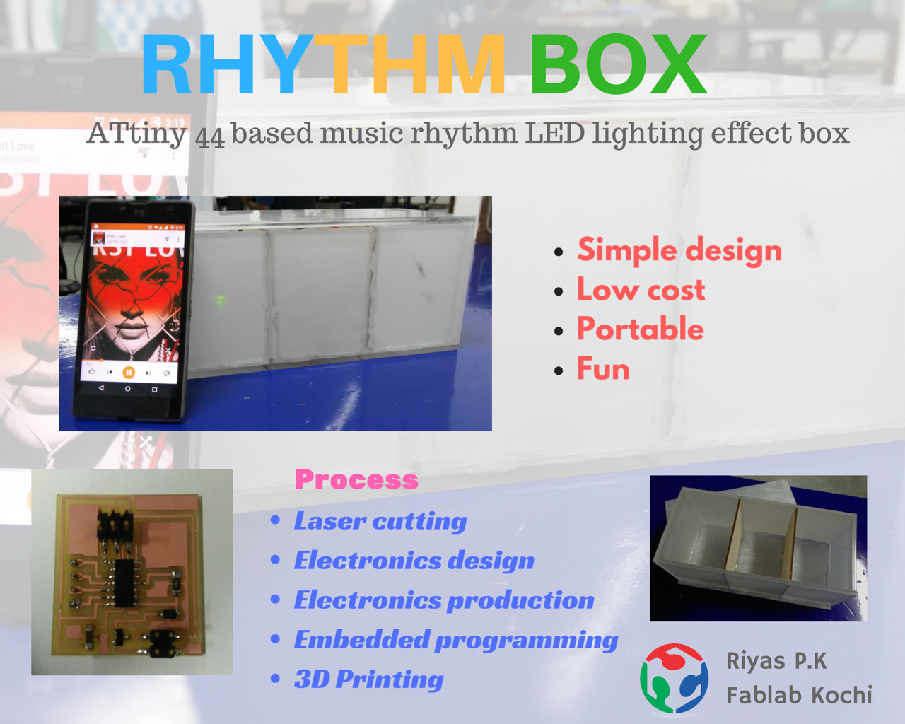
Rhythm Box
An Attiny 44 based music rhythm led lighting effect box, which is simple and fun.Also as an add on, a 3D printed sound dock with charging port.
Overview
My initial idea was to create a modular wireless speaker, but due to the exams I wasn't available at the lab about 20 days.So,the plans have changed.I am forced to take another project which needed to be simple and should be completed within the time limit.After looking up internet and previous year's archives, I decided to go with rhythm box.
Rhytm box is a led lighting effect box, which uses the sound values from analog input pin.The sound source is a smartphone connected with a aux cable to the circuit.It uses a attiny 44 micro controller.it's not a correct way to analyze sound/audio signals but it will flash the LEDs in music rhythm.The whole project is simple and is done by following processes.
Computer-Aided Design
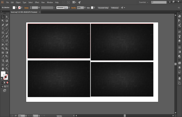
The first stage of my project was desigining the frame.As the project to be kept simple I decide to make the shape as a basic rectagular box with three compartments.I saw my friend Nizam joining acrylic sheet pieces with glue gun for his project, so I decided to do it as well.Because of that I only need to draw few recatgles with certain dimensions,for this I used adobe illustrator.Since I was using a transparent acrylic sheet, inorder to get the light effect I need to engrave it entirely.For this I added a black texture image inside all the rectangles.Since the PC coonected to laser cutter only have inkscape I saved the file in svg format.
Designing sound dock
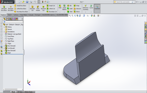
As an add on to the project I decided to make a sound dock for my phone.The sound dock will enhance the sound output of a phone by varying area of sound path.I used solid works to design the sound dock.I got some inspirations regarding the design from various interenet resources. Since my phone had back speakers I needed to take account for that.This is one of the drawbacks of my design, because it can't use for phones having bottom speakers.
What I did for the design was, first made a basic shape without any holes.
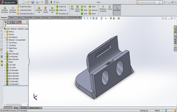
Then I using extrude cut feature I added holes.On second thought I added hole for charging cable to be directly connect to the phone.
See the design in sketch fab:
Files:
Computer Controlled Cutting
After loading up the design in inkscape and the print option is given, the laser cutter starts its process.The engraving is done so as to reduce the transperancy level to 50%,this ensures good led lighting effect.Since the engraving is needed for whole parts, the process took considerable amount of time as compared to other laser cutting jobs I have done before.Instead of engraving the transparent acrylic sheet you can purchase plexi glass which will have same effect.I preferd acrylic sheet because it is readily available in our lab.
After cutting the parts I joined them to form the shape using a glue gun.For dividing the box to three compartments I used two pieces of plywood.
Electronic Design
I designed the attiny board for my project in eagle.The circuit is simple, it has a attiny 44 micro controller and it is connected to four pin ports.I decided to use pull up resistors and led's, that's why using pin ports.Since I am using a battery as power source I added a voltage regulator and a diode.For audio input I tried to add the 2.5mm audio conn jack, which is the only audio jack available in our lab.But during designing I couldn't find it on fab library or any other library,even from internet.So I decided to use male to female audio (with 3.5mm jack) cable by cut it in the half.So the audio input also will be connected via pin port.
Schematic:
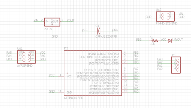
Board
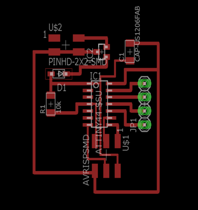
Files
Electronic Production
The designed circuit is milled using milling machine.And the parts are stuffed.This was the time I realized I made a design mistake.I should have added more holes.
Embedded Programming
First I wrote a simple program in arduino after refering some example programs.The idea is to read the incoming data from audio signal and store it to 'data' variable.Then using this values, led's can be controlled.This is working similar to as a VU meter.But there is no waveform analyzing.I have added three conditions, if the data value from the sound is between 5 and 20 the first set of leds lights up,else if the values are between 20 and 40 and the values are between 40 and 800 lights up the second set and third set of leds correspondingly.
          /*  ATtiny 44 based music rhythm led lighting box.
            *  Riyas P.K 2016                                */

            //Constants
            const int audioSignal = 5; //Audio signal - left or right channel - to pin 0 of ATtiny
            const int firstLed   = 0; //First led (from left) to pin 1 of ATtiny
            const int secondLed  = 1; //Second led to pin 2 of ATtiny
            const int thirdLed   = 2; //Third led to pin 3 of ATtiny

            //Variables
            int data; //Will store the incoming data from audio signal

            void setup()
            {
            //Define input and output pins
            pinMode(audioSignal, INPUT);
            pinMode(firstLed, OUTPUT);
            pinMode(secondLed, OUTPUT);
            pinMode(thirdLed, OUTPUT);
            }

            void loop()
            {
            //Read the incoming data from audio signal and store it to 'data' variable
            data = analogRead(5);

            //Make some cases to control the LEDs.


            if (data > 5 && data < 20 ) {
            digitalWrite(firstLed, HIGH);
            }

               else if (data >= 20 && data < 40) {
               digitalWrite(secondLed, HIGH);
            }
               else if (data >= 40 && data <= 800) {
               digitalWrite(thirdLed, HIGH);
            }
            else {
              digitalWrite(firstLed, LOW);
              digitalWrite(secondLed, LOW);
              digitalWrite(thirdLed, LOW);
                 }
              delay(20); // a small delay
            }
The board is programmed using fab isp and arduino ide.
Then I tested the connections.
File
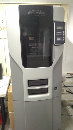
3D Printing
This is the first time I am using the dimension 1200es 3d printer in our lab.I have seen many of others using it.The end product has good finish, it mainly used when more complex are to be printed.It uses ABS filament for model along with a support material (ecoworks).
I opened my stl file in the catalyst ex software, which is the companion software for dimension printers.First I changed the orientaion of the part from orienation menu.Then I clicked on process stl,now the software shows the amount of materials required.Then clicked on add to pack which shows the position, number of items etc.
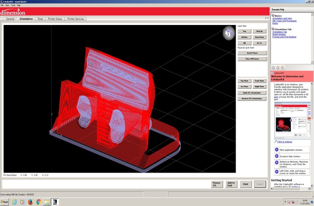
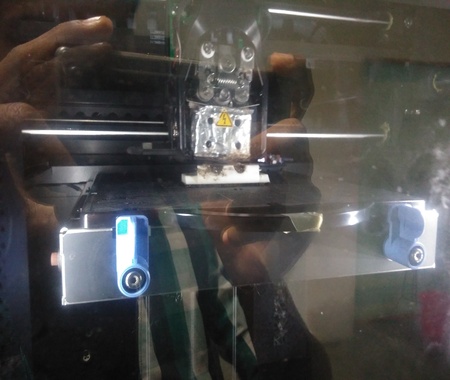
Before printing, the printer should be switched on for a while to heat up.After clicking on print option, press print on the printer switch.This starts the printing process.It took about 4.30 hours to print my part.
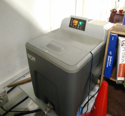
After finishing the printing, inorder to remove the support material from the part, it is put into the support cleaning apparatus.The time is set to 12 hours and temperature set at 70 degree celsius.
Here is the finished part:
Slide:
Working video: