*NEW* Final Project: FabKickBoard - a motorized Kickboard
How it comes
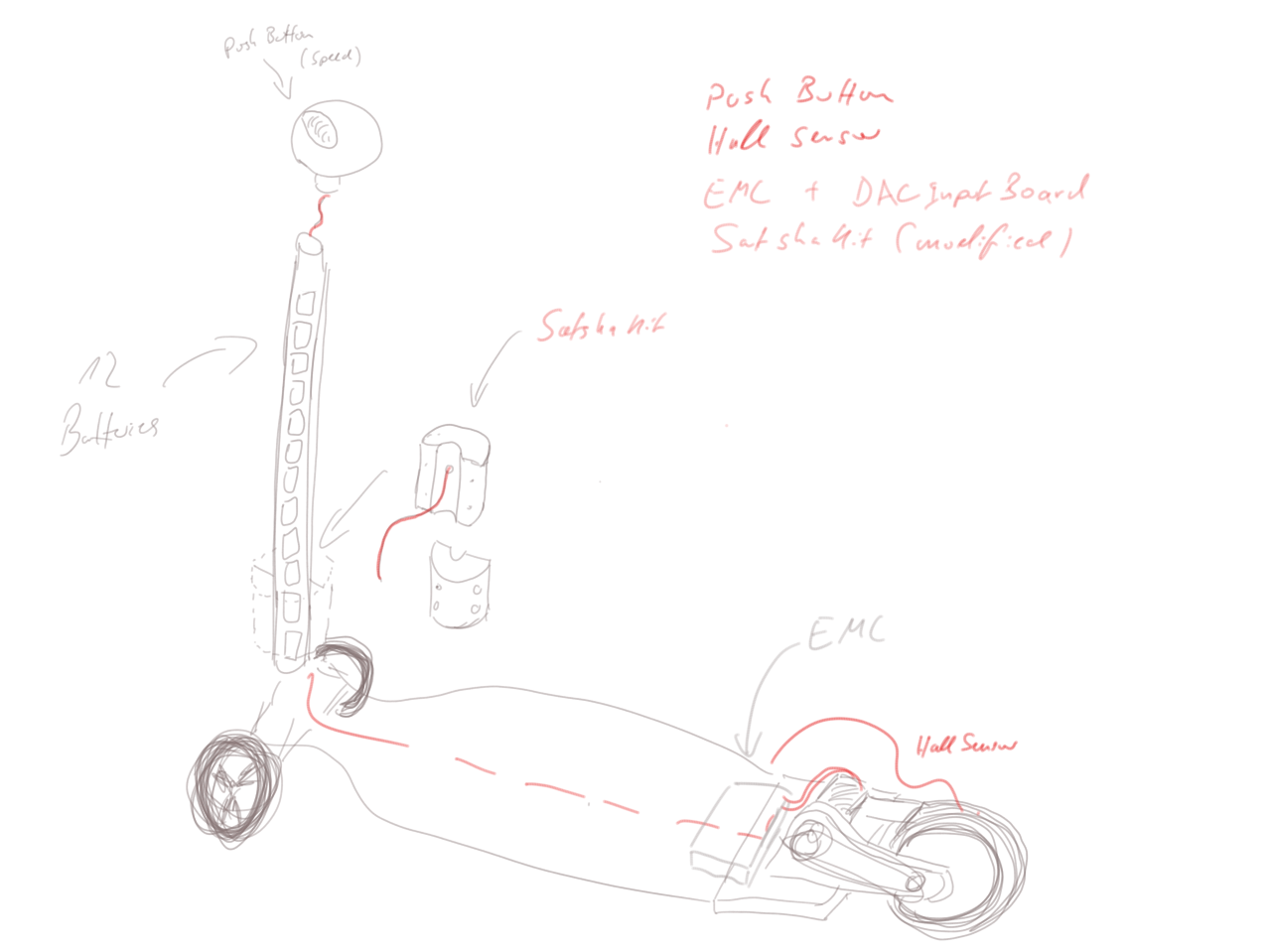
Somewhere in between week 11 and 14 I decided to do a shift of focus for the final project. This has two reasons: First, the eBike project turned out to be too complex in the way I want it to be and second, I was taken by the motorized K2 Kick Board idea in weeek 12 (Molding and Casting).Here is the new concept of my final project:
How to MAKE it
FOLLOWING WAS AN ONGOING DOCUMENTATION while I was woking on the final project. It is written in a (more or less) chronological order.
For my final project I have to deal with different parts - electrotechnical, mechanical, programming and assembly.
I started with the research for an adequate motor, motor control (ESC) and batteries.
Batteries
Ater a while of reseach, I decided to get 12 of these batteries: LG Lithium Ion INR18650 HG2 3000mAh Akku.
In a configuration of 6S2P, they will deliver 22,2 V, continious current of 40A and energy of 133,2 W/h.
The batteries do not have any connectors. Some solder wires to the poles but heat might damage the batteries. Some just tape wires to the poles but it might end up in detaching (especially in my case, because of vibrations while driving).
I found this neat way, I might consinder for my solution: magnets:


Motor & ESC
For the motor I did some research, too. I was looking for one with 8-10mm shaft (because of constructional reasons) and low kv as well.A really nice motor would have been the one of hobbyking: Turnigy G110 Brushless Outrunner 295kv (1.10 Glow), which unfortunately was out of stock.
Spec.
Battery: 8~9S Cell /29.6~33.3V
RPM: 295kv
Max current: 55A
No load current: 10V/1.2A
Current capacity: 65A/15sec
Internal resistance: 0.03 ohm
Weight: 485g  (not including connectors)
Diameter of shaft: 8mm
Dimensions: 79x63mm

Required;
85A HV ESC
8S~9S Li-Po / 24 ~ 32-cell Ni-MH/Ni-Cd
17x8 ~ 19x10 prop

Suitable for sport and scale airplanes weighing 9 to 15 pounds (4–6.8 kg).
Thats why I go with the Alien 6374 Outrunner brushless motor 170KV 3200W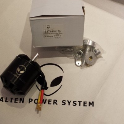
MOTOR: 6374
KV: 170
MAX POWER: 3200W
WIRE WINDS: 10
MAX AMP: 80A
ESC: 100/150A
MAX VOLT: 10S
RESISTANCE: .56
NO LOAD CURRENT: 1,4
SIZE: 63 x 74 ( without shaft )
WEIGHT (g): 0,750
SHAFT: 10mm with 3mm keyway
Accessory pack: Yes
Keyway: 3mm
As ESC I will use the TURNIGY K-Force 120A-HV OPTO V2 5-12S Brushless ESC
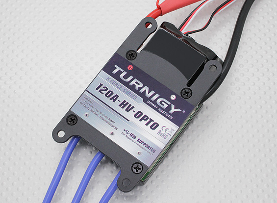
Specification:
Output: Continuous 120A, burst 180A up to 10 seconds.
Input Voltage: 5-12 cells lithium battery or 15-36 cells NIMH battery.
BEC:  None.
Control Signal Transmission: Optically coupled system.
Max Speed;
  2 Pole: 210,000rpm
  6 Pole: 70,000rpm
  12 pole: 35,000rpm
Size: 88mm (L) * 55mm (W) * 15mm (H).
Weight: 125g.
Requirements (for the electronics/PCB)
Based on the components above I planned the features of the board which have to be designed in a PCB (and programmed accordingly).
As Daniele was with us, I got in touch with the satshakit.

satshakit is a 100% Arduino IDE and libraries compatible, fabbable and open source board, and also an improved version of Fabkit.https://github.com/satshas/satshakit
Main improvements and features over Fabkit are:
16Mhz instead of 8Mhz
crystal instead of resonator
costs less (7-9 euro vs 13 euro)
100% compatible with default Arduino IDE (satshakit is recognized as Arduino UNO)
ADC6/7 connected instead of ADC6/7 not connected (satshakit laser and cnc)
larger space to easy soldering (satshakit laser and cnc)
Modified satshakit & Components
Following is a list of Pins, needed for my project. I made this list, because I need to know the changes to be made to the satshakit.
1x Analog: (10 g bis 10 kg; > 1 MΩ auf ca. < 3 kOhm ) pressure sensor and its datasheet. (speed);
+ eventually you need a resistor (5k)
+ eventually GND
+ VCC
1x Digital: button (cruise control on/off);
+ need a 10k resistor
+ VCC
+ GND
1x Digital: PWM for controlling the ESC
+ VCC (because of this special ESC, as mentioned already)
+ GND
2x Digital: RX & TX Serial Communication from the ADCInputBoard (Hall)
+ GND
Component: Voltage Regulator (Pulu)
I want to use the batteries to power the satshakit. Thus, I need to regulate the power.
VCC to the battery: Vin
+ GND
VOut to the satshakit and ADCInputBoard
Component: Measure voltage
When driving the board, I want to know the status of the batteries. I want to show at least status: full charged, average, need to charge. Therefor I used a RGB LED.
1 AnalogIn: To measure voltage of batteries, you need a voltage divider/partitioner (yust 2 resistors).
3x DigitalOut: Output of voltage (RGB LED 1050466);
+ needs 3 Resistor 500Ohm
+ GND
VCC & GND
Counting the number of VCC and GNDs, a conclusion sathaKit needs:
5+1 additional VCCs
6+1 additional GND
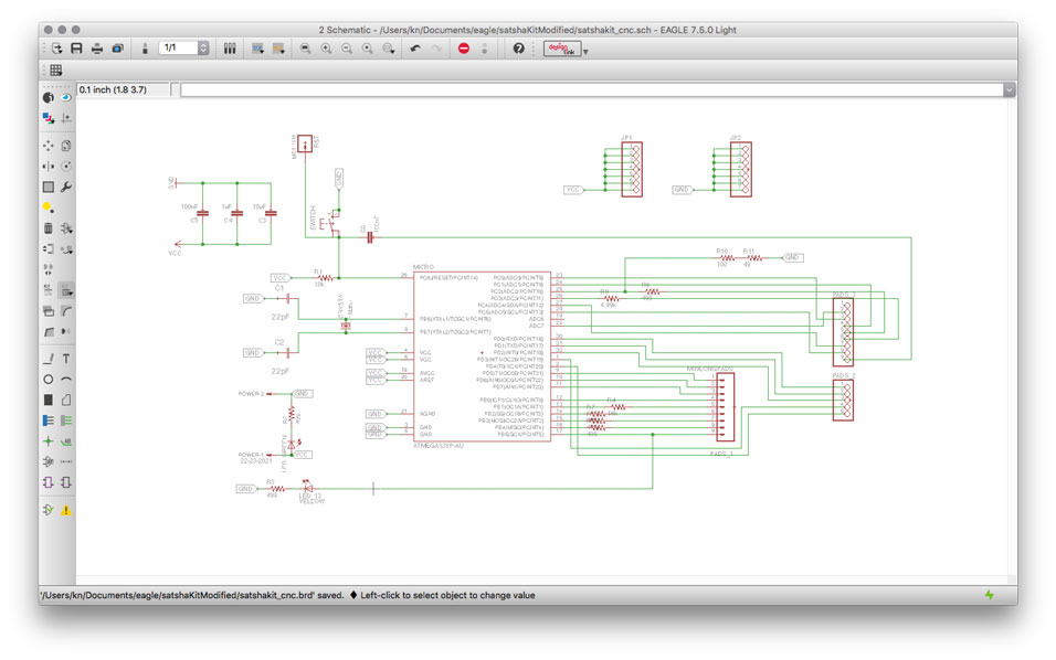
Modifying the schematics and sayout
When deleting ADC6 in order to have free space for GND and VCC (because it is on the back end of the board and therefore easyly accessible).
I Did and added two 7x1 Pin Header.
For the RGB LED:
PB2,3,4 will be used for the RGB LED later on. The LELD is not on the board but the resistors can be put there already.
Thats why I modified the satshakit here accordingly.
So Pins 12,11,10 (+GND) will be used for the LED directly.
PB5 (pin 13) will be untouched, because I might need the onboard LED.
PB1 (pin 9) will be used for the button (digital).
For the analog signals I decided to use not PCIN12 and PCIN13 because they are reserved for I2C.
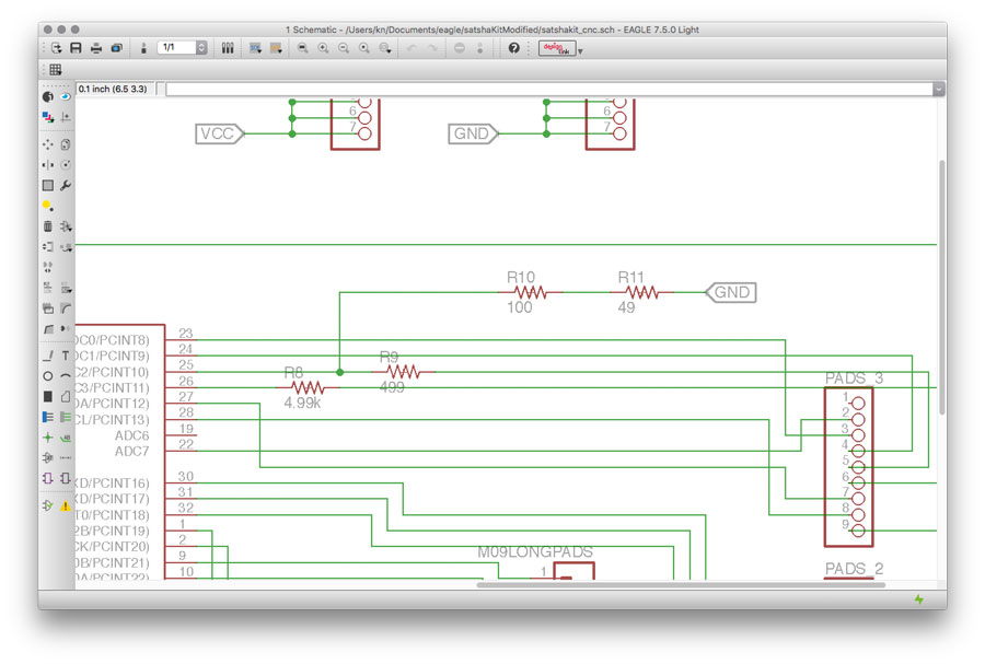
Thats why I use PCIN11 (pin A3). I also added a 4.99k resistor (even though it is not necessarily needed).
For the batteries, you should never go below 12V to not kill the battery.
Better is to never go below 80% of the battery.
The voltage of the (new) battery is dropping from 16.8V to 13.2V (non-linear), but this might kill the battery.
For the Lithium Ion battery (4S setting) the working parameters are between 4.2V (16.8V) and 3.6V (14.4V) - to not kill the battery.
e.g. https://learn.adafruit.com/li-ion-and-lipoly-batteries/voltages
With the voltage regulator I want to measure the range between 4.2V (16.8V) and 3.6V (14.4V). Therefore I have to map it:
The Chip can measure between 5 and 0 volts.
4.2V (16.8V) = 5V (better 4V for safety reasons)
and 3.6V (14.4V) = 0
http://www.daycounter.com/Calculators/Voltage-Divider-Calculator.phtml
R1 = 499Ohm
R2 = 100 + 49 Ohm
I used PCINT10 for that (pin A2)
Version 1 of the modified satshakit


For the modified satshakitv1 I use Pin 6 to control the Motor.
int controlPin = 6; //PWM to control the motor
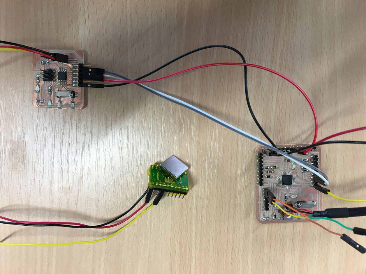
I also changed the code to measure the hallSensor via soft serial to a higher baudrate. It is capable of 9600baud.
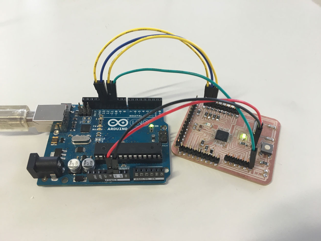
When connecting the satshakitv1 with the ADCInputBoard and with the ESC we figured out that serial communication did not work proper. The initialization/arming of the motor (ESC) did not work anymore.
Maybe it is because the hardware serial communication and the software serial cannut use the same ports. I checked the datasheed and decidet to use a different port for soft serial.
Then it works.
NO, IT DID NOT ...
Solution: have to use hardware serial communication.
Or: use ADCInputBoard just as a sensor and e.g. just send a signal, once the motor has mada 1 turn. This can then be read in by the satshakit as digital input. Thus, it is a oneway serial communication.
Once again, I had to change the satshakitv1 to make a v2. The resistor for the button has been placed wrong. It must have been connected after, not before the pins.
I also changed pins I intended to use for the RGB LED. Pins are now: 5,6,9
Pin10 is used for the Button as it is connected with a 10k resistor after the pin to pull it down .
Also: changes to the pushbutton (Force Sensing Resistor):
1mOhm is like an open cirquit for the analog signal.
And an open analog cirquit does create bouncing values.
So either I have to use a different analog sensor/button (with less resistance) or I have to use a different cirquit.
I did change the cirquit (such as http://archive.fabacademy.org/2016/fablabvigyanashram/students/93/senforce.jpg) so that I still could use the Force Sensing Resistor.
I also had to change the intended pin to A4:
int pressSensorPin = A4
// voltage divider
I tested the voltage divider with the satshakitv1 (just in case something might happen).
Resistors started to heat up.
Thus, I changed the resisors values.
(https://www.akkuline.de/downloads/technisches-datenblatt-inr18650hg2-li-zelle-3-0ah-15384-1.pdf)
We have fixed voltage: 6S2P
https://www.akkuline.de/downloads/technisches-datenblatt-inr18650hg2-li-zelle-3-0ah-15384-1.pdf
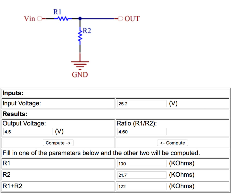
4,2 V per Battery = 25,2 V max
Standard value for SMD resistors (max power the resistor can consume/absorb): 0.25W
so, P should be less than 0,25W to not kill the components.
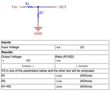
http://www.daycounter.com/Calculators/Voltage-Divider-Calculator.phtml
Input Voltage: 25,2 (V)
Results:
Output Voltage:
4,5 (V)
R1 100 (KOhms)
calculates:
Ratio (R1/R2): 4,6
R2 21,7 (KOhms)
R1+R2 122 (KOhms)
I can use R1 (100k) + R2,R3 (10k+10k)
Tested it. Worked well. With a full powered battery I got vales close to 1000 (940 to be precise).
That means, by having 25V and
// 37,6 per 1 Volt
Range 25V > 21,6 (min, because in the datasheet it is mentioned that the batt min voltage is 3,6V)
940 * 21,6V / 25V = 812,16 which is the minimun value read by the input pin. I must not runt the motor below this value.
// final connections:
A3 for the flexsensor
VCC to flexsensor
pin10 for button
VCC to button
pin11 to ESC
VCC to ESC
GND to ESC
pin5,6,9 for RGB LED
GND (cathode)
940 -820 = 120 / 2 = 60

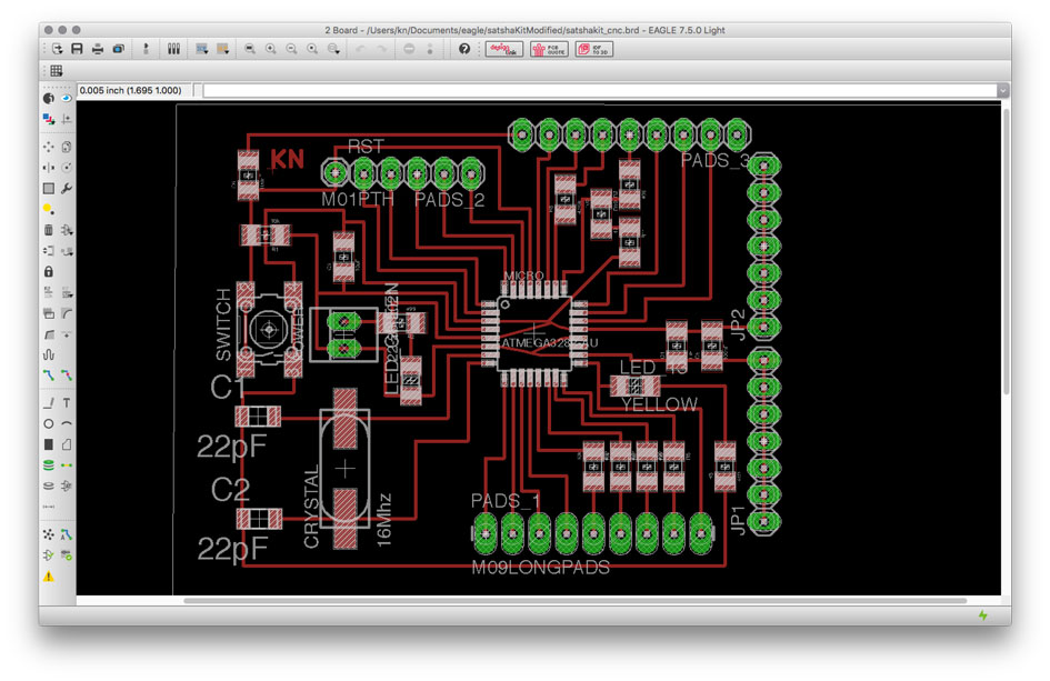
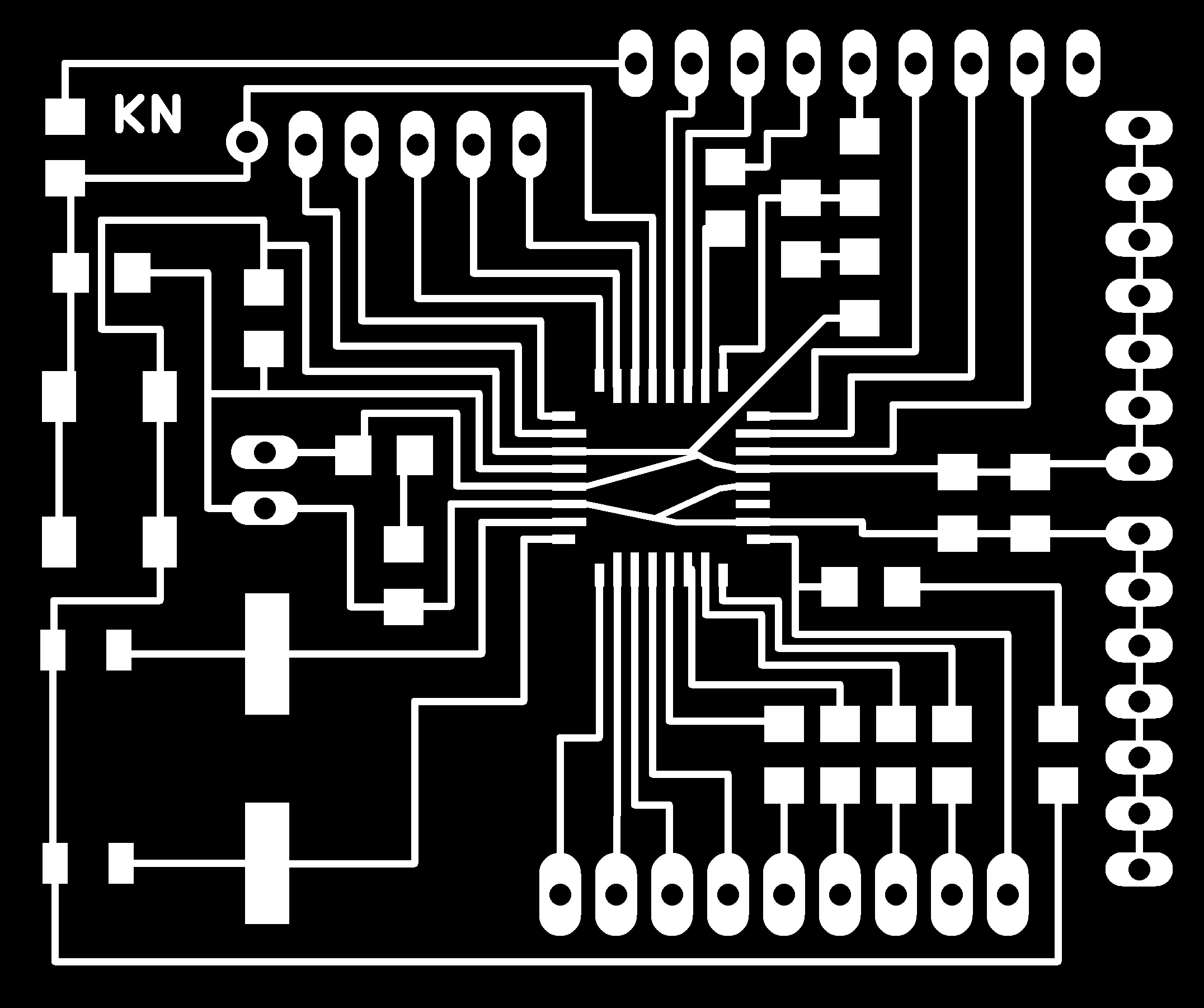
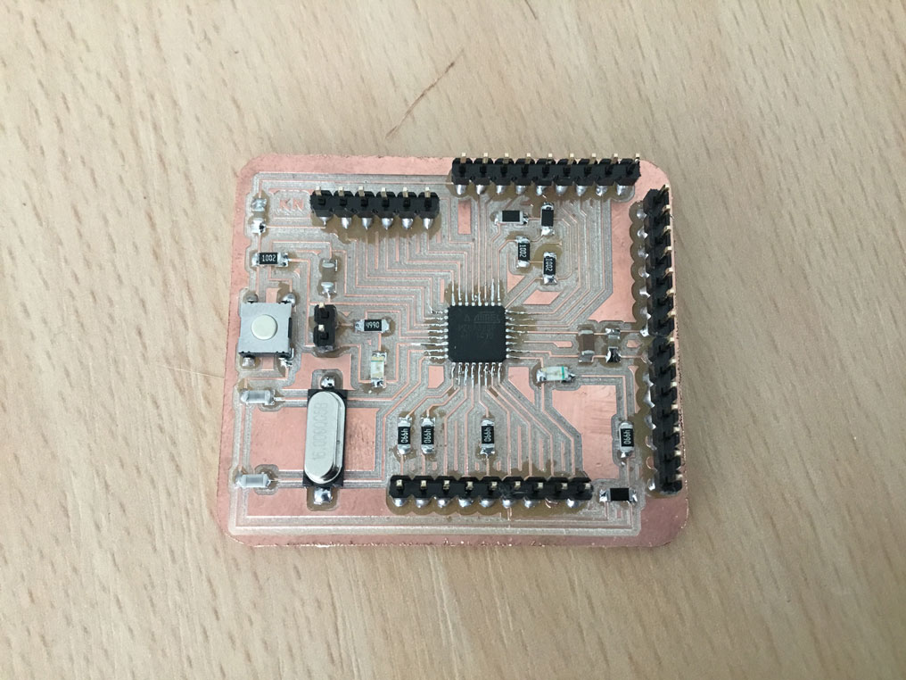
Following image shows the final layout of the modified satshakit and labels to the pins.
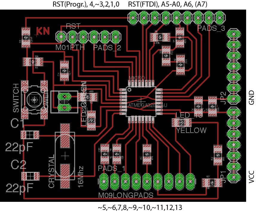
And here is the full board soldered:
About the code, I wanted to implement a safety feature in a way that I need always to press the button to operate the motor of the fabKickBoard. Also, as this motor is really powerful, it was required to start it slowly to avoid to move the fabKickBoard with too much power at the beginning. I always check about the button status in the loop(), and then only if the button is pressed, the speed of the motor is slowly increased by simultaneously keeping pressed the pressure button. In this case increasing the speed of a value of 1 each time that the loop will check the status of the pressure sensor. If the button will be released, then the fabKickBoard motor will stop spinning. The LED will show the status of the motor, if it's green, this means that the motor is fully stopped, if it's purple, then this indicates that the motor is moving.
Following is the full code:
// This sketch uses the servo library to arm the ESC.

#include <Servo.h>
#include <SoftwareSerial.h> // we need to establish software serial communication


//  ***** motor control  *****
Servo esc; // Define the ESC as a servo object
int controlPin = 11; //PWM to control the motor
int arm = 1078;    // defines pulse width (measured: 1078; 1765 & tested: 1200 for starting (1190 while slowing down); max)
int speedvalue = 0;
int steady = 300;
int initiate = 0;
int speedTest = 0;
int throttle = 0;


#define MINSPEED 1100 // motor is off
#define MAXSPEED 1400
int sendSpeed = 0;      // value send to the motor (mapped in the range of MINSPEED & MAXSPEED)


// ***** pressure sensor *****
int pressSensorPin = A3;      // pressure sensor connected to pin
int pressSensorCalibrate = 0; // starting value of the sensor
int pressSensorValue = 0;     // life time value of the pressure sensor
int pressSensorMax = 300;
int pressSensorValueMin = 0;
int pressSensorValueMax = 100;


// ***** simple button *****
int buttonPin = 10 ; // will be used for the button (digital).
int buttonPressed;


// ***** ADCInput board *****
int hallValue = 0; // rpm measured by the ADCInputBoard and send via softSerial
// set RX TX for serial communicaton
const byte rxPin = A0;
const byte txPin = A1;
//SoftwareSerial mySerial ( rxPin, txPin); // set up a new software serial object


// ***** voltage divider ******
int voltagePin = A0;
int voltageValue= 0;
#define battRangeMax 940
#define battRangeMin 820

// **** RGB LED *****
int rgbPinR = 5;
int rgbPinG = 6;
int rgbPinB = 9;
#define COMMON_ANODE


void setup()
{
  // initialize & arm motor
  esc.attach( controlPin , 1200, 1700);
  esc.writeMicroseconds( arm ); // This command sends a pulse train
                              // from pin 9 that continues until
                             // the pin is called to do something else.


  // initialize serial communication
  Serial.begin(9600);     // hardware serial
//  mySerial.begin(9600); // software serial communication with the ADCInput board to read the hallSensors value


  // set button pin
  pinMode( buttonPin, INPUT );

  // set input for voltage divider
  pinMode( voltagePin, INPUT );

  // set rgb led
  pinMode( rgbPinR, OUTPUT );
  pinMode( rgbPinG, OUTPUT );
  pinMode( rgbPinB, OUTPUT );


  Serial.println( "Ready to rumble" );

}

void loop()
{


 // serial communication with the ADCInput board to read the hallSensors value
/*
    while (mySerial.available() > 0) {
      hallValue = mySerial.parseInt();
//      Serial.print("Hall: ");
//      Serial.println(hallValue);
    }
*/

    // read button
    buttonPressed = digitalRead( buttonPin ); // set HIGH if the button is pressed

    // read pressure sensors life values
    pressSensorValue = analogRead( pressSensorPin );
    //Serial.println( String("Pressure: ") + pressSensorValue );


  if ( buttonPressed == HIGH ){
    // only increase speed if the button is pressed

            if ( pressSensorValue > 800 ) {
                speedvalue = speedvalue + 1;
                if ( speedvalue > MAXSPEED ) speedvalue = MAXSPEED;
                //Serial.println("INCREASE");
                  setColor(255, 0, 0);

            }
            else if ( pressSensorValue > 200 && pressSensorValue <= 800 ) {
              // nothing
            }

    } else
    {
      // if the button is not pressed, reset speedValue (by this, turn the motor off)
          speedvalue = MINSPEED; // motor off
                  setColor(0, 255, 0);

      }


    Serial.println( String("Speed: ") + speedvalue );
    esc.writeMicroseconds( speedvalue );


  // read voltage level of the batteries
    voltageValue = analogRead( voltagePin );
    //Serial.println( String("VCC:") + voltageValue );


/*

    if ( voltageValue <= battRangeMin ){
        // minimum voltage level of the battery
        setColor(255, 0, 0);  // red
        Serial.println( String("VCC: RED") + voltageValue );
    }
    else if ( voltageValue <= battRangeMax - ((battRangeMax - battRangeMin )/ 2) ) {
          // medium voltage level of the battery
          setColor(0, 0, 255);  // blue
          Serial.println( String("VCC: BLUE") + voltageValue );
    }
    else {
        setColor(0, 255, 0);  // green
        Serial.println( String("VCC: GREEN") + voltageValue );
    }

*/


    //sendSpeed = map( pressSensorValue, pressSensorValueMin, pressSensorValueMax, MINSPEED, MAXSPEED);
/*
    while (Serial.available() > 0) {
      Serial.print("pressure: ");
      Serial.print( pressSensorValue );
      Serial.print("(");
      Serial.println( sendSpeed );
      Serial.print(")");
    }
*/

/*

  // read from serial input and send value to motor
    while (Serial.available() > 0) {
      speedTest = Serial.parseInt();
      Serial.print("Speed: ");
      Serial.println(speedTest);
    }
    if (speedTest > 0) esc.writeMicroseconds(speedTest);


*/

}

void setColor(int red, int green, int blue)
{
  #ifdef COMMON_ANODE
    red = 255 - red;
    green = 255 - green;
    blue = 255 - blue;
  #endif
  digitalWrite( rgbPinR, red);
  digitalWrite( rgbPinG, green);
  digitalWrite( rgbPinB, blue);
}
Here can see the code in action with the fabKickBoard:
modified satshakit to run and control BDCMotor using flexiforce pressure sensor from usableDesign on Vimeo.
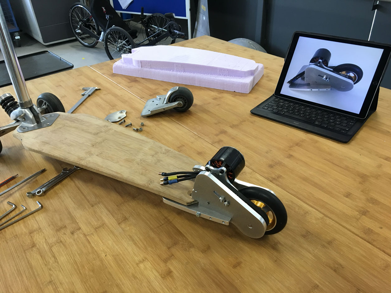
Designing the mechanical parts
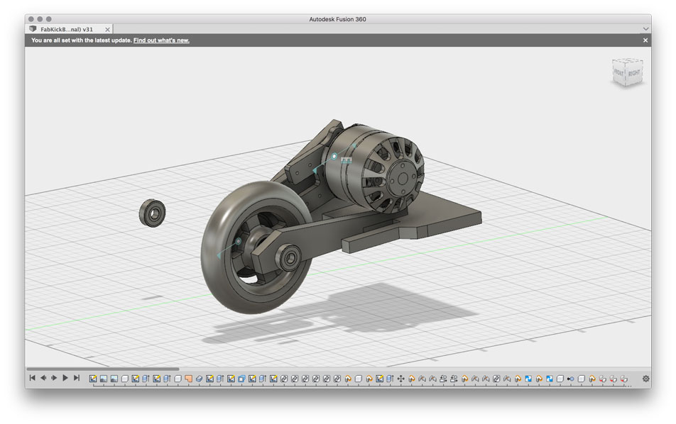
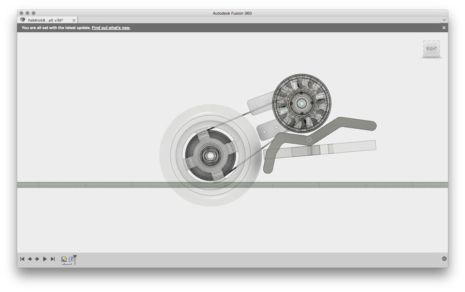
From the technical point of view I had to create a motor mount, a new rod (which includes the batteries), a handle (with buttons included) and a enclosure for the electronic components (as mentioned above).Luckily I could find an Alien Drive motor on grabcad to download.. I had to adjust the length because the outrunner's body was smaller than the one I had.
For the axle I use standard 6092RS bearings from FAG. The CAD-files could be downloaded from their website.
The timing Belt Pulleys' CAD-Data I got from the Maedler webpage. I use two different types. A small one and the bigger one.
For the design I used Fusion360.
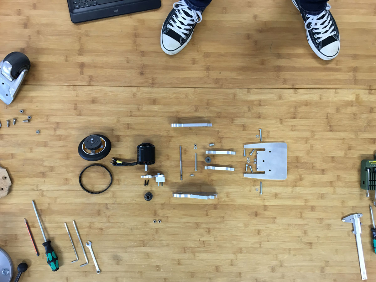
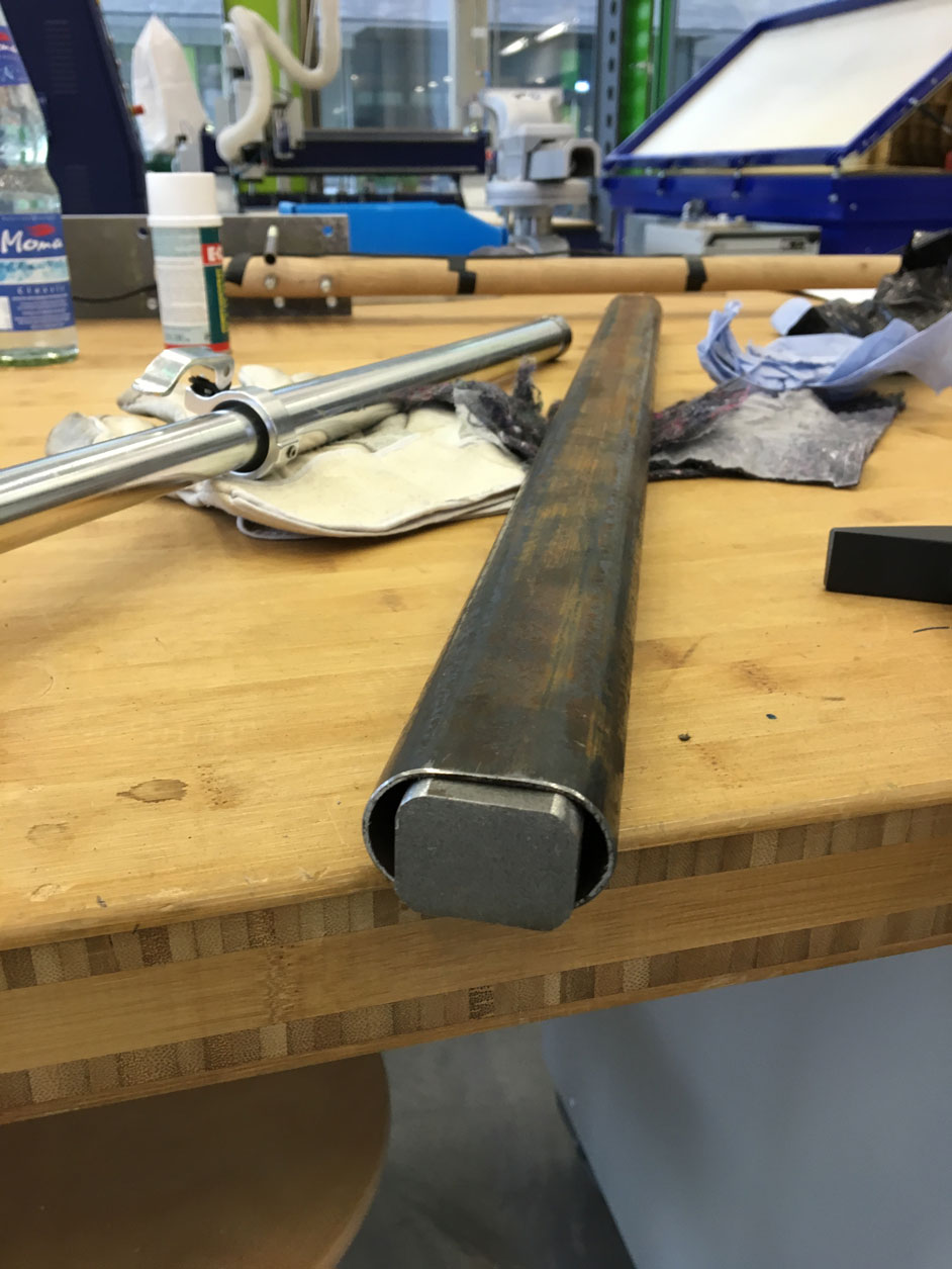
Production and assembly
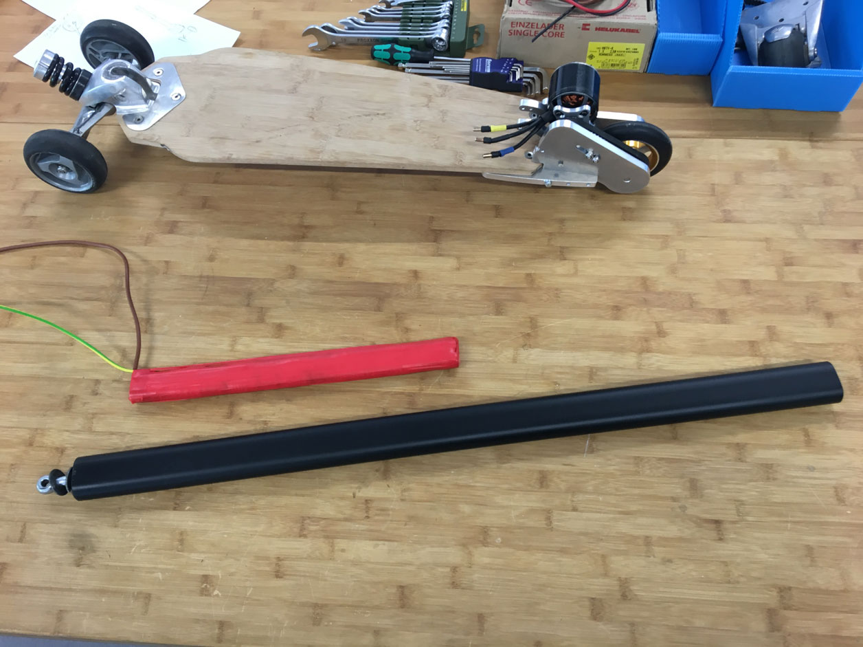
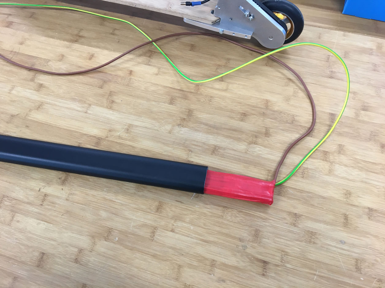
After milling the parts, I started with the assembly. I disassembled the rod of the old K2 board because I needed the one end. There was a screw thread which I need to attach the new rod to its designated position. There is a mechanism that enables the user to fold it together (for tansportation). I did some welding, abrading, painting, etc.
I taped the batteries tightly together and put them in the rod.
Milling the axle for the fabKickBoard from usableDesign on Vimeo.


3D Prints: Housing, Handle, Brake-Pedal
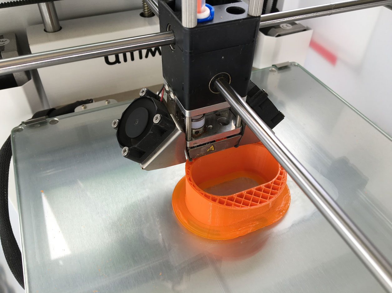
As I wanted the buttons to be implemented into the handle, I decided to print it. Therefor I measured the sizes of the rod and designed a hollow body in which I made cutouts for the buttons. As material, I used FexFillament. Printing it was not as easy as expected, because the object started loosening while printing. The solution was, to create it with a really big brim (100 in the ultimaker's settings).
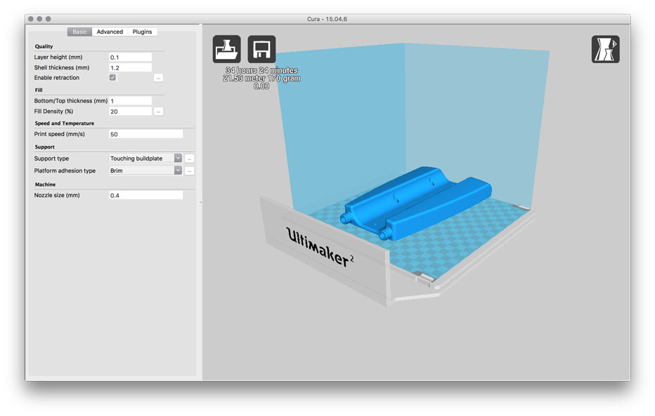
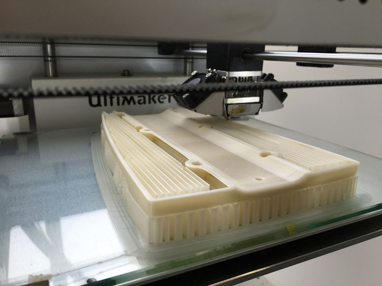
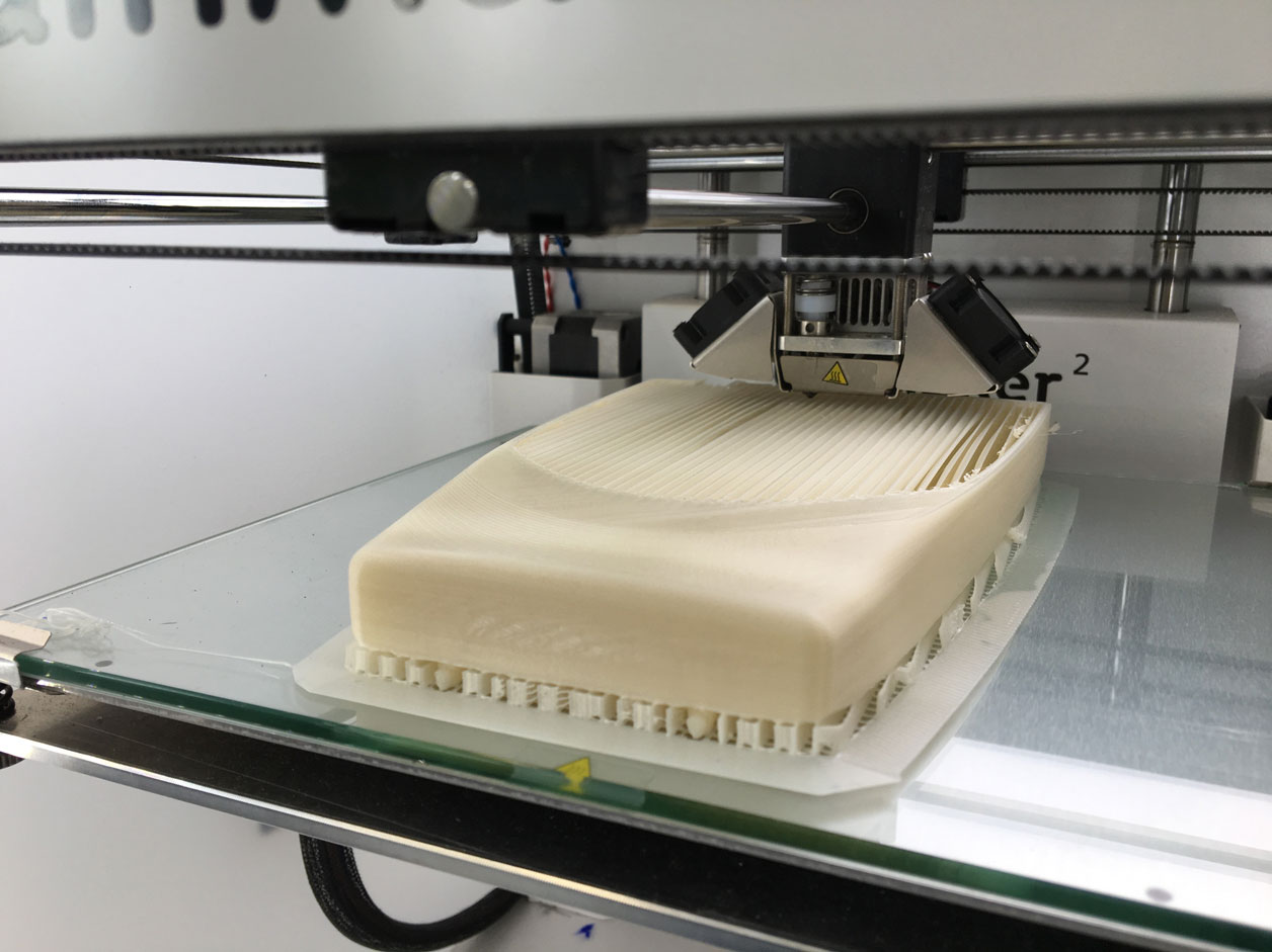
The electronics housing was also 3D designed and printed. The print of each one of the two half shells took almost 24hrs. Glad, that we have several Ultimakers in the FabLab Kamp-Lintfort, so that I could print in parallel.
FINALs
At the end - I MAKEd it ;)
Here is the final poster and video, I have made for my final presentation.

fabKickBoard - FabAcademy 2016 Final Project by Karsten Nebe from usableDesign on Vimeo.
Outlook
My plans for further development on my final project are:
- add test-cables to charge the battery in a contolled way.
- re-make the electronics housing (little bigger and may be cast it instead of printing it)
- implement the battery status
- make a new board that includes the cables