The motor driver (NJM2670) is more complex than the structure is A4953, it took time to understand the end of the cable.
See below picture
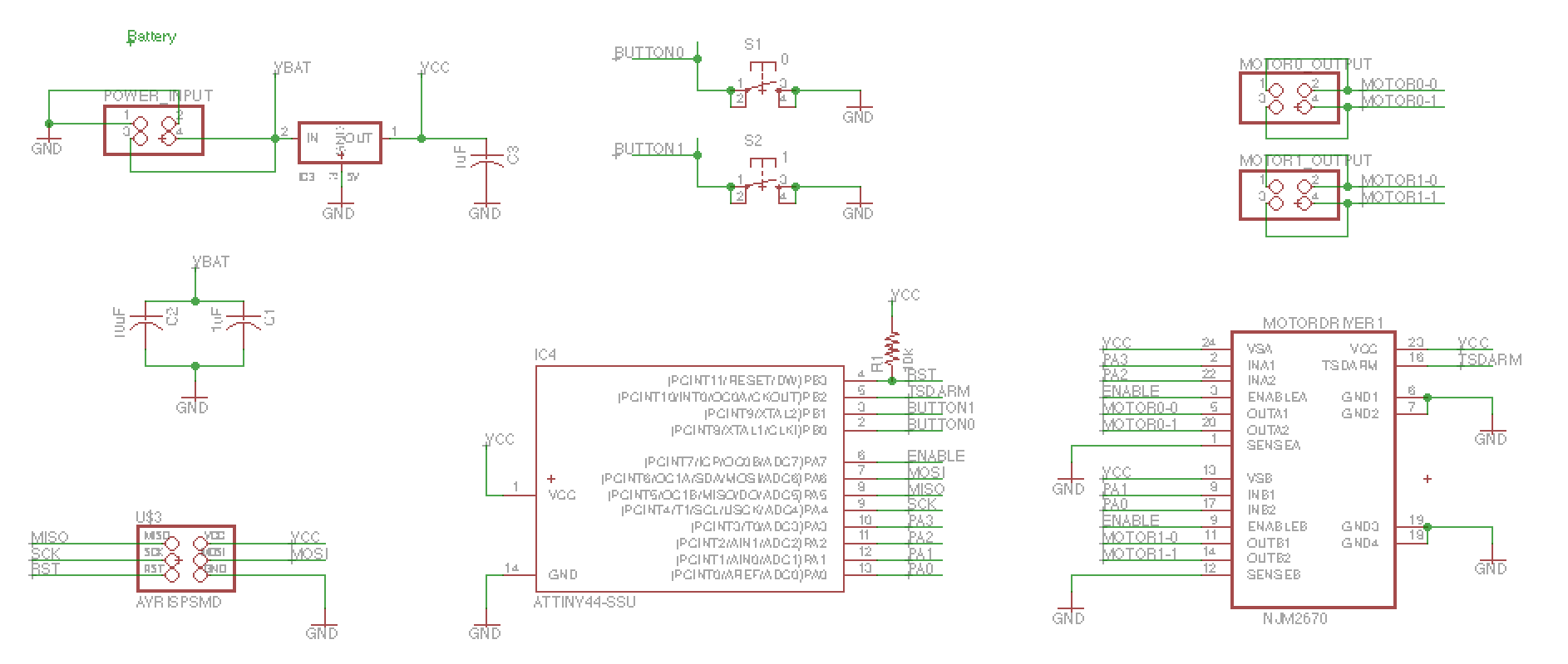
To add a Motor x2 and switch x2
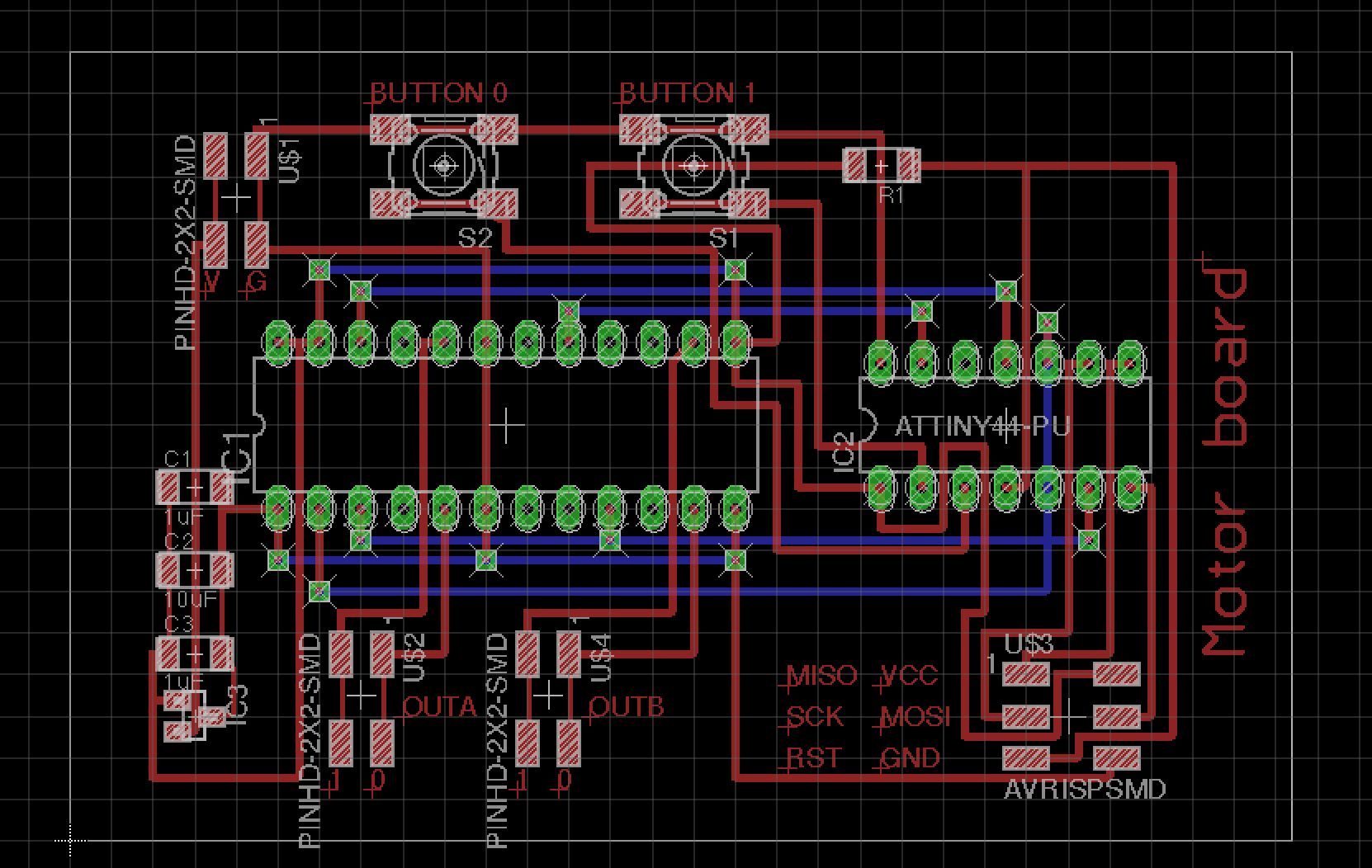
Wiring has many struggling to routing of the cable.
These wiring could not be wire on one side.
It was also to be the wiring on the back.
Board design see below.
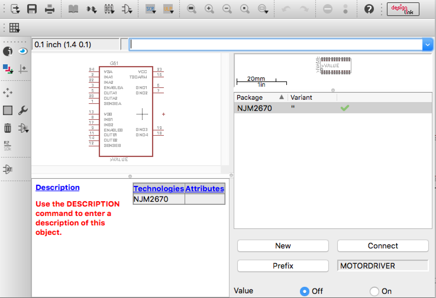
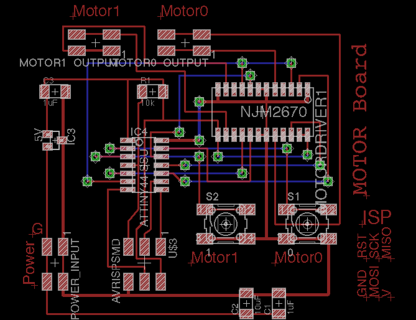
This was cut out in the milling machine, but I have noticed a big mistake.
It was different the size of the ATTINY44 and NJM2670.
So ATTINY44 could be changed to small size from the library.
But, NJM2670 was newly created for this circuit.
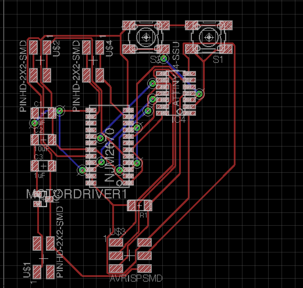
Modified circuit is very small.
It can not be wiring between the for ATTINY of foot
Routing of the wiring was difficult.
I updated the design of board.
This board is need 8 wiring on back board.
RML data:rml_data
Eagle Data:motor_x2_and_button_x2v1.zip
Currently still during fabrication.
I use blashless motor unit at final project.
Please see final project page.
Back to home